University of Windsor University of Windsor
Scholarship at UWindsor
Scholarship at UWindsor
Electronic Theses and Dissertations Theses, Dissertations, and Major Papers
3-10-2019
A Hybrid Indoor Location Positioning System
A Hybrid Indoor Location Positioning System
Shuo Li
University of Windsor
Follow this and additional works at: https://scholar.uwindsor.ca/etd
Recommended Citation Recommended Citation
Li, Shuo, "A Hybrid Indoor Location Positioning System" (2019). Electronic Theses and Dissertations. 7643.
https://scholar.uwindsor.ca/etd/7643
This online database contains the full-text of PhD dissertations and Masters’ theses of University of Windsor students from 1954 forward. These documents are made available for personal study and research purposes only, in accordance with the Canadian Copyright Act and the Creative Commons license—CC BY-NC-ND (Attribution, Non-Commercial, No Derivative Works). Under this license, works must always be attributed to the copyright holder (original author), cannot be used for any commercial purposes, and may not be altered. Any other use would require the permission of the copyright holder. Students may inquire about withdrawing their dissertation and/or thesis from this database. For additional inquiries, please contact the repository administrator via email
A Hybrid Indoor Location Positioning System
By
Shuo Li
A Thesis
Submitted to the Faculty of Graduate Studies
through the Department of Electrical and Computer Engineering
in Partial Fulfillment of the Requirements for
the Degree of Master of Applied Science
at the University of Windsor
Windsor, Ontario, Canada
A Hybrid Indoor Location Positioning System
by
Shuo Li
APPROVED BY:
______________________________________________ G. Reader
Department of Mechanical, Automotive and Materials Engineering
______________________________________________ S. Erfani
Department of Electrical and Computer Engineering
______________________________________________ R. Muscedere, Co-Advisor
Department of Electrical and Computer Engineering
______________________________________________ R. Rashidzadeh, Co-Advisor
Department of Electrical and Computer Engineering
iii
DECLARATION OF CO-AUTHORSHIP/PREVIOUS PUBLICATIONS
I. Co-Authorship
I hereby declare that this thesis incorporates materials that are the results of joint
research, as follows: Chapter 3 of the thesis was co-authored with Dr. Rashid
Rashidzadeh. Chapter 4 of the thesis was co-authored with Dr. Rashid Rashidzadeh
and Dr. Roberto Muscedere. In all cases, the key ideas, primary contributions,
experimental designs, data analysis, interpretation, and writing were performed by
the author. Dr. Rashid Rashidzadeh contributed to the statistical analysis and
graphing results; Dr. Roberto Muscedere provided feedback on refinement of ideas
and editing manuscript.
I am aware of the University of Windsor Senate Policy on Authorship and I certify
that I have properly acknowledged the contribution of other researchers to my thesis
and have obtained written permission from the co-author to include the materials in
my thesis.
I certify that, with the above qualification, this thesis, and the research to which it
refers, is the product of my own work.
II. Previous Publications
This thesis includes 2 original articles that have been previously
published/submitted for publication in peer reviewed journals, as follows:
Chapter Publication Title Publication Status
Chapter -3 S.Li, R. Rashidzadeh, "A Hybrid
Indoor Location Positioning
System,” 2018 IEEE
International Conference on
Electro/Information Technology (EIT), Rochester, MI, 2018, pp. 0187-0191.
Published
Chapter -4 S.Li, R. Rashidzadeh and R. Muscedere, "An Indoor Location Estimation System with Fine and
iv
Coarse Positioning Modes," IET Wireless Sensor Systems.
I certify that I have obtained a written permission from the copyright owner(s) to
include the above published material(s) in my thesis. I certify that the above material
describes work completed during my registration as a graduate student at the
University of Windsor.
III. General
I declare that, to the best of my knowledge, my thesis does not infringe upon
anyone’s copyright nor violate any proprietary rights and that any ideas, techniques,
quotations, or any other material from the work of other people included in my
thesis, published or otherwise, are fully acknowledged in accordance with the
standard referencing practices. Furthermore, to the extent that I have included
copyrighted material that surpasses the bounds of fair dealing within the meaning of
the Canada Copyright Act, I certify that I have obtained a written permission from
the copyright owners to include such materials in my thesis.
I declare that this is a true copy of my thesis, including any final revisions, as
approved by my thesis committee and the Graduate Studies office, and that this
thesis has not been submitted for a higher degree to any other University or
v ABSTRACT
Indoor location positioning techniques have experienced impressive growth in
recent years. A wide range of indoor positioning algorithms has been developed for
various applications. In this work a practical indoor location positioning technique
is presented which utilizes off-the-shelf smartphones and low-cost Bluetooth Low
Energy (BLE) nodes without any further infrastructure. The method includes coarse
and fine modes of location positioning. In the coarse mode, the received signal
strength (RSS) of the BLE nodes is used for location estimation while in the fine
acoustic signals are utilized for accurate positioning. The system can achieve
centimeter-level positioning accuracy in its fine mode. To enhance the system’s
performance in noisy environments, two digital signal processing (DSP) algorithms
of (a) band-pass filtering with audio pattern recognition and (b) linear frequency
modulated chirp signal with matched filter are implemented. To increase the
system’s robustness in dense multipath environments, a method using data
clustering with sliding window is employed. The received signal strength of BLE
nodes is used as an auxiliary positioning method to identify the non-line-of-sight
(NLoS) propagation paths in the acoustic positioning mode. Experimental
measurement results in an indoor area of 10 m2 indicate that the positioning error
vi
DEDICATION
vii
ACKNOWLEDGEMENTS
I would like to thank my supervisor Dr. Rashid Rashidzadeh for his guidance,
encouragement and support to complete my research studies. I am grateful for his
involvement, mentoring and his constructive technical advice.
I am grateful to my co-supervisor Dr. Roberto Muscedere for his valuable comments
and technical support which help me to improve my work and overcome technical
challenges.
I would also like to thank my committee members Dr. S. Erfani and Dr. G. Reader
for their constructive comments and positive criticism.
I would like to extend my gratitude to my colleagues at the Research Centre for
Integrated Microsystems (RCIM). I appreciate their friendship, support,
encouragement, their constant involvement and valuable feedback.
Finally, I would like to thank the research and financial support received from
Natural Sciences and Engineering Research Council (NSERC) of Canada and
viii
TABLE OF CONTENTS
DECLARATION OF CO-AUTHORSHIP/PREVIOUS PUBLICATIONS ... iii
ABSTRACT ... v
DEDICATION ... vi
ACKNOWLEDGEMENTS ... vii
LIST OF TABLES ... xi
LIST OF FIGURES ... xii
LIST OF ABBREVIATIONS ... xiv
Chapter -1... 1
Introduction ... 1
1.1 Indoor Location Based Applications and Accuracies ... 1
1.2 Dual Mode Positioning ... 1
1.3 System Cost and Smartphone Compatibility ... 2
1.4 Problem Statement: Lack of a Practical Indoor Positioning System ... 2
1.5 Research Goals ... 3
1.6 Thesis Overview ... 3
1.7 References ... 4
Chapter -2... 5
Related Work ... 5
2.1 RF Signal ... 5
2.2 Audio Signal ... 5
2.3 Light Signal and Magnetic Field... 6
2.4 Strengths and Weakness of the Proposed Solutions ... 6
2.5 References ... 7
Chapter -3... 8
A Hybrid Indoor Location Positioning System ... 8
3.1 Introduction ... 8
3.2 General Positioning Method ... 9
3.2.1 Dual Mode Positioning... 9
ix
3.3 Fine Positioning Approach ... 11
3.3.1 Multilateration Positioning ... 11
3.3.2 TDoA Measurement ... 12
3.3.3 Audio Signal Arrival Detection ... 14
3.4 Experimental Validation ... 17
3.4.1 System Prototype ... 17
3.4.2 Experiment Setup ... 18
3.4.3 Experiment Result ... 19
3.5 Conclusion ... 19
3.6 References ... 19
Chapter -4... 21
An Indoor Location Estimation System with Fine and Coarse Positioning Modes 21 4.1 Introduction ... 21
4.2 Related Work ... 22
4.3 System Overview ... 23
4.3.1 Dual Mode Positioning... 23
4.3.2 Multilateration Positioning ... 23
4.4 ToA Estimation ... 27
4.4.1 Linear Frequency Modulated Chirp & Matched Filtering ... 27
4.4.2 Indoor Acoustic Environment Modeling ... 29
4.4.3 Noise Filtering ... 31
4.4.4 ToA Point Selection ... 33
4.4.5 NLoS Identification ... 37
4.5 Experimental Validation ... 40
4.5.1 System Prototype ... 40
4.5.2 Wireless Communication ... 41
4.5.3 Optimal Node Placement ... 41
4.5.4 Experiment Setup ... 42
4.5.5 Experiments Results ... 46
4.6 Conclusion ... 46
4.7 References ... 46
x
Conclusions and future work ... 50
5.1 Conclusions ... 50
5.2 Future Work ... 51
APPENDIX : COPY RIGHT PERMISSION... 52
xi
LIST OF TABLES
Table # Caption Page #
1 Comparison of Different
Systems 7
2 Noise Correlation
xii
LIST OF FIGURES
Figure # Caption Page #
1 An indoor environment
divided to 3 grids 11
2 Smartphone and audio receivers’ coordinates 11
3 Audio signals received at
2 audio receivers 14
4 Audio signal emitted
from smartphone 14
5 Noise near 17 KHz 15
6 Sensortag used as an
audio receiver 17
7 Screenshot of the
developed app 17
8 Experiment setup 18
9 Experiment results in
quiet environment 19
10 Experiment results in
noisy environment 19
11 An indoor environment
covered with the system 25
12
Time-of-Arrivals (ToAs) for two nodes and the corresponding Time Difference of Arrival (TDoA)
25
13 Smartphone and audio
receivers 26
14
Received chirp signal transferred through a propagation channel with non-flat frequency response
30
15 ToA peak and highest
peak 31
16
The calculated threshold for the propagation channel to filter out the noise
33
17
Positive part of c[n] with
𝑵𝑻𝒐𝑨 = 6615, 𝑭𝒔=44.1 KHz
36
xiii
19 Separated audio data
clusters 37
20 First local maxima as
ToA 37
21 Local maxima indicating
the ToA point 38
22 LoS condition 39
23 NLoS condition 39
24
The output of the cross correlation for an experiment where (a) with a line-of-sight connection and (b) without a line-of-sight connection between transmitters and receivers
40
25 Wireless communication 41
26
TDoA error tolerance ability with respect to z coordinates
43
27
The area where the experimental measurements were performed
44
28 TDoA experiment results
in quiet environment 45
29 TDoA experiment results
in noisy environment 45
30 TDoA results under
dense multipath effects 46
31 Position estimation
xiv
LIST OF ABBREVIATIONS
RSS Received Signal Strength Indication
RF Radio Frequency
GPS Global Positioning System
BLE Bluetooth Low Energy
SNR Signal-to-noise Ratio
TDoA Time-Difference-of-Arrival
UWB Ultra-wideband
RFID Radio Frequency Identification
WLAN Wireless LAN
ToA Time-of-Arrival
PDA Personal Digital Assistant
IoT Internet of Things
LoS Line-of-sight
NLoS Non-line-of-sight
AoA Angle-of-Arrival
CDMA Code-division Multiple Access
ToF Time-of-flight
1
Chapter -1
Introduction
The need for an indoor location positioning system has risen dramatically in recent years.
The global indoor positioning market is expected to grow at an annual rate of 58.9% from
2017 to 2021 [1]. Indoor location positioning techniques can improve the services provided
by health care centers, smart homes, indoor parking lots, museums and shopping malls.
The design of a cost-effective and accurate indoor positioning is a challenging task. The
existing global positioning system (GPS), which is a mature positioning solution, doesn’t
work properly in indoor locations. A GPS based positioning system requires a line of sight
connection between transmitters and receivers to ensure positioning accuracy. A practical
indoor positioning solution is expected to be cost-effective, easy to use and accurate [2].
1.1Indoor Location Based Applications and Accuracies
In general, the accuracy required for indoor positioning is higher than the accuracy required
for outdoor navigation. GPS can achieve less than 7.8 meters error in 95% of cases which
is good enough for many outdoor positioning applications [3], however, for an indoor area,
such an error is not acceptable for most applications.
In a typical application scenario such as a shopping mall, a meter level positioning accuracy
[4] is enough to find the desired locations and shops. However, inside a shop, a centimeter
level accuracy may be needed to find an item in a department such as a pair of shoes. As
presented in this typical application, initially a coarse localization system meets the
positioning requirements and then a fine positioning system is needed to locate desired
items. In general, a high positioning accuracy increases the costs and power consumption.
Using a hybrid system with coarse and fine positioning capacity reduces the costs.
1.2Dual Mode Positioning
The proposed system in this work can switch between a meter-level coarse mode
positioning and a centimeter-level fine positioning mode. The coarse positioning mode is
based on the Received Signal Strength (RSS) method while the fine positioning mode
2
i. Fine positioning mode: In the fine mode the system utilizes sound pulses
transmitted from a smartphone to perform the positioning. A smartphone can
generate sound with the maximum frequency of about 20 KHz [5]. BLE tags with
the capacity to detect the transmitted audio signals are placed at known locations in
the environment. The BLE tags calculate the Time of Arrival (ToA) for the received
audio signals and send this information back to the smartphone to determine its
location.
ii. Power consumption: The DSP algorithms for the fine mode are computationally
costly. To decrease the power consumption, the micro-controller is set to operate
in the sleep mode. It is only activated when a high accuracy positioning is required.
iii. Coarse positioning mode: Though the audio-based positioning method can
achieve a centimeter level accuracy, it consumes a considerable amount of power.
The systems by default operate in the RSS based positioning mode [6] which
consumes less power and switches to the fine-positioning mode when it is needed.
Moreover, the BLE RSS positioning mode is used as a reference to detect outliers
in the fine-positioning mode.
1.3System Cost and Smartphone Compatibility
The system’s cost includes the costs of the resources needed for deployment and
maintenance. The deployment costs mainly cover the costs of hardware, such as the tags
and the costs of roaming devices. To lower the costs, the total number of tags have to be
optimized, which means that the coverage area for each beacon should be as large as
possible. After installation, the cost mainly comes from the battery replacement and
software updates.
Considering the ubiquity of smartphones, a system requiring nothing but a smartphone at
the user side appeals more to customers compared to a system requiring custom designed
devices.
1.4Problem Statement: Lack of a Practical Indoor Positioning System
In general, for indoor people location tracking and positioning, a system should be
3
There are many RSS-based indoor positioning systems proposed in the literature, they can
achieve meter-level accuracy, however, many indoor applications require centimeter level
accuracies. There are also some high accuracy indoor positioning systems, but they are
relatively costly. Some ultrasound solutions can achieve both high accuracy and low cost,
but they are not smartphone compatible.
1.5Research Goals
The main purpose of this work is to develop an indoor positioning solution that can be
implemented for real-world applications. The main contributions of this thesis are:
i. A new hybrid indoor positioning system with coarse and fine positioning modes is
designed, implemented and tested. The implemented system is cost-effective and
supports cellphone platforms.
ii. A new DSP algorithm is developed to increase the range and to overcome the
environmental noise and multipath effects in the fine positioning mode.
1.6Thesis Overview
This thesis is organized as follows:
Chapter -1 introduces the research topic, provides an overview of the related work and
available indoor positioning methods.
Chapter -2 discusses the proposed indoor positioning solutions, compares their strengths
and weaknesses.
Chapter-3 presents the hardware implementation and the corresponding positioning
algorithms. This work has been published in the 2018 IEEE International Conference on
Electro/Information Technology (EIT).
Chapter-4 presents the hybrid positioning solution and the associated DSP algorithms. The
results of this work have been submitted to the journal of IET Wireless Sensor Systems for
review.
4
1.7References
[1] I. Market, "Indoor Location Market by Technology & application - Global Forecast
2022 | MarketsandMarkets," Marketsandmarkets.com, 2018. [Online]. Available:
https://www.marketsandmarkets.com/Market-Reports/indoor-positioning-navigation-ipin-market-989.html. [Accessed: 23- Nov- 2018].
[2] S. Li, R. Rashidzadeh, "A Hybrid Indoor Location Positioning System," 2018 IEEE
International Conference on Electro/Information Technology (EIT), Rochester, MI,
2018, pp. 0187-0191.
[3] "GPS.gov: GPS Accuracy," Gps.gov, 2018. [Online]. Available:
https://www.gps.gov/systems/gps/performance/accuracy/. [Accessed: 23- Nov- 2018].
[4] R. Brena et al., "Evolution of Indoor Positioning Technologies: A Survey, " Journal of
Sensors, vol. 2017, Article ID 2630413, 21 pages, 2017.
https://doi.org/10.1155/2017/2630413.
[5] F. Höflinger et al., "Acoustic Self-Calibrating System for Indoor Smartphone Tracking
(ASSIST)," 2012 International Conference on Indoor Positioning and Indoor
Navigation (IPIN), Sydney, NSW, 2012, pp. 1-9.
[6] F. Zaki, R. Rashidzadeh, "An Indoor Location Positioning Algorithm for Portable
Devices and Autonomous Machines," International Conference on Indoor Positioning
5
Chapter -2
Related Work
There are many indoor positioning solutions proposed in the past. They can be mainly
classified as follows [1]:
i. RF signal.
ii. Audio signal.
iii. Light.
iv. Magnetic field and other signals
2.1RF Signal
The common solutions using RF signals are based on BLE, Wi-Fi, ZigBee, Radio
Frequency Identification (RFID) and UWB technologies. The systems using BLE, Wi-Fi
and ZigBee technologies are often range-based systems utilizing the Received Signal
Strength (RSS). There are commercial solutions such as Apple’s BLE iBeacon,
Ekahau using wireless LAN (WLAN) fingerprint and Netvox ZigBee. For the systems
using UWB, the positioning results come from the Angle-of-Arrival (AoA) or the
Time-Difference-of-Arrival (TDoA) of the UWB signals. An example of the commercial UWB
system is Ubisense Real-Time Location System [1].
2.2Audio Signal
The systems using audio signal often determine a positioning using the Time-of-Arrival
(ToA) or TDoA of an audio signal. ActiveBat and Cricket are the successful positioning
systems using ultrasound. ActiveBat is an active ultrasonic positioning system while the
latter one is passive [2-3]. They can both achieve centimeter-level accuracy using
ultrasound. However, these system do not support cellphone platforms and they require
custom design hardware. There are also systems using audible or near ultrasound to
support cellphone platforms. For example, Beep uses audible sound signal transmitted from
a Personal Digital Assistant (PDA) [4], ASSIST uses near ultrasound signal transmitted
from a smartphone [5]. Smartphones are used as audio receivers in ALPS and Akkurate for
6
2.3Light Signal and Magnetic Field
There are systems using light and magnetic field for indoor location estimation. Infrared
technology and visible light are both utilized for positioning. There are also systems that
utilize the earth’s natural magnetic field without any further infrastructure, a commercial
example of this type of system is IndoorAtlas [1].
2.4Strengths and Weakness of the Proposed Solutions
The strengths and weaknesses of the systems proposed in the past are summarized in
Table-I using accuracy and smartphone compatibility as criteria for comparison.
TABLE I. COMPARISION OF DIFFERENT SYSTEMS
Signal types Accuracy Smartphone Compatibility
BLE Around 1 m Yes
Wi-Fi Around 1 m Yes
UWB <10 cm No
ZigBee Meters Yes
RFID 1-5 m No
Ultrasound <10 cm No
Audible/Near ultrasound
<10 cm
Yes
Light Meters Some
Magnetic field Meters Yes
Form the above table it can be concluded that systems using audio signals support a higher
7
2.5References
[1] R. Brena et al., "Evolution of Indoor Positioning Technologies: A Survey, " Journal of
Sensors, vol. 2017, Article ID 2630413, 21 pages, 2017.
https://doi.org/10.1155/2017/2630413.
[2] N. Priyantha, A. Chakraborty and H. Balakrishnan, "The cricket location-support
system," Proc. ACM Conference on Mobile Computing and Networking, 2000.
[3] A. Ward, A. Jones and A. Hopper, " A New Location Technique for the Active Office,"
IEEE Personal Communications, Vol. 4, No. 5, October 1997, pp. 42-47.
[4] A. Mandal et al., "Beep: 3D indoor positioning using audible sound," Second IEEE
Consumer Communications and Networking Conference, 2005. CCNC. 2005, Las
Vegas, NV, 2005, pp. 348-353.
[5] F. Höflinger et al., "Acoustic Self-calibrating System for Indoor Smartphone Tracking
(ASSIST)," 2012 International Conference on Indoor Positioning and Indoor
Navigation (IPIN), Sydney, NSW, 2012, pp. 1-9.
[6] L. Patrick et al., "ALPS: A Bluetooth and Ultrasound Platform for Mapping and
Localization," 73-84. 10.1145/2809695.2809727.
[7] S. Lopes et al., "Accurate smartphone indoor positioning using a WSN infrastructure
and non-invasive audio for TDoA estimation," Pervasive and Mobile Computing,
Volume 20, 2015, Pages 29-46. https://doi.org/10.1016/j.pmcj.2014.09.003.
[8] R. Balani, "Energy Consumption Analysis for Bluetooth, WiFi and Cellular
Networks," Document, Electrical Engineering, University of California at Los
8
Chapter -3
A Hybrid Indoor Location Positioning System
3.1 Introduction
The use of indoor location positioning systems has risen significantly in recent years. They
are widely used in areas such as health care centers, smart homes and shopping malls.
Location positioning with a high level of accuracy in indoor environments is proven to be
challenging [1]. Indoor positioning systems utilizing electromagnetic waves and received
signal strengths suffer from multipath effects which reduces the positioning accuracy
considerably.
There are many indoor positioning solutions in the literature using various techniques and
technologies such as vision, infrared, ultrasound, WLAN/Wi-Fi, RFID and ultrawide-band,
to perform accurate positioning. The positing accuracy for methods utilizing Received
Signal Strength (RSS) from WiFi access ports or Bluetooth tags is limited due to the nature
of electromagnetic wave propagation in indoor environments. To increase the positioning
accuracy to less than a meter in these methods custom designed devices are commonly
needed [2]. However, using such devices increases the costs considerably. There is need to
a cost-effective and easy to use indoor positioning solution with a high accuracy.
Smartphones have already become a daily necessity for many across the globe, a practical
and low cost indoor solution can utilize smartphone resources. The audio system in a
typical smartphone can deliver audio signals with frequencies higher than 16 KHz. Such
audio signals can be used to implement an acoustic positioning system for indoor
environments [3].
In the proposed method in this work, only a smartphone is required at the user side for
indoor localization. In the fine positioning mode, short audio wave pulses are transmitted
through smartphones. Low cost BLE audio receivers in the environment receive the
transmitted signals. Then the positioning system measures the time differences of arrival
(TDoA) of the audio signals at different locations to calculate the cellphone position. The
9
positioning accuracy. To improve the system’s performance against environment noise, a
band pass filter is utilized and a pattern recognition algorithm is developed. The
communication between the positioning system and nearby smartphones is performed
through BLE tags to reduce the power consumption. The use of BLE tags for localization
allows the integration of the proposed positioning system with internet of things (IoT)
networks.
The rest of the paper is organized as follows. Section II explains the principal of operation
for the proposed localization method and its operation modes. Section III covers the details
of the implemented acoustic positioning system. The experimental measurement results are
presented in section IV and section V summarizes the results and presents the conclusions.
3.2General Positioning Method
3.2.1 Dual Mode Positioning
The proposed system combines a coarse positing method using RSS with a fine positioning
technique using acoustic signals. A smartphone application is developed to implement the
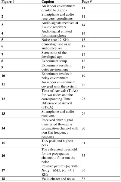
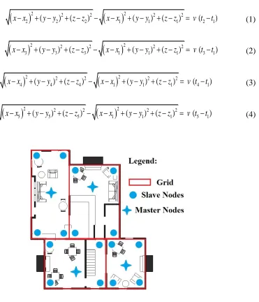
positioning algorithm. As shown in Fig. 1, the indoor area is divided into grids, each grid
is covered with BLE tags used as audio receivers. These tags can switch between BLE
broadcasting mode and audio sampling mode. By default, the positioning is performed in
the coarse mode using the RSS based method. If a more accurate positioning is needed, the
user sends a request by the application on the smartphone to switch the mode of nearby
BLE tags to the audio sampling mode. Then acoustic signals are used for multilateralization
for a centimeter-level positioning accuracy.
3.2.2 System Architecture
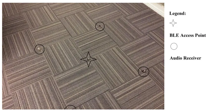
The proposed positioning system includes audio receivers and BLE access points. The
audio receivers and BLE access points are both BLE tags with different firmware. The
acoustic signal is generated by user’s smartphone for positioning. As shown in Fig.1, each
grid in the diagram is covered by four audio receivers and one BLE access point, the audio
receivers with known positions serve as anchor points. These receivers periodically
10
positioning in this work, the RSS weighted average is implemented to achieve meter-level
positioning accuracy [4].
Fig. 1. An indoor environment divided to 3 grids.
11
3.3Fine Positioning Approach
3.3.1 Multilateration Positioning
Smartphone operating systems have audio latency problems that limit their application for
accurate time measurement. The elapsed time between a smartphone’s audio code
execution and the time when the audio is actually played cannot be accurately determined
[5]. As a result, in the proposed method in this work instead of the time-of-arrival the Time
Difference of Arrival (TDoA) is used for positioning [6]. In the proposed method the
distance differences between each audio receiver to the smartphone are required. Fig. 2
illustrates a smartphone and audio receiver’s coordinates in a typical indoor environment.
Audio receivers serve as anchor points and their x, y, z coordinates are known. These
coordinates in Fig. 2 can be described as follows.
x
x
2 2
(
y
y
2)
2
(
z
z
2)
2
x
x
1 2
(
y
y
1)
2
(
z
z
1)
2
v
(
t
2
t
1)
(1)
x
x
3
2
(
y
y
3)
2
(
z
z
3)
2
x
x
1 2
(
y
y
1)
2
(
z
z
1)
2
v
(
t
3
t
1)
(2)
x
x
4 2
(
y
y
4)
2
(
z
z
4)
2
x
x
1 2
(
y
y
1)
2
(
z
z
1)
2
v
(
t
4
t
1)
(3) v indicates the sound speed considered to be 340 m/s, and t1-t4 indicate the prorogationtime from a smartphone to different receivers. It can be seen from the above equations that
accurate TDoA measurement is the key for accurate positioning.
We used Chan algorithm [7] to solve the equations. Equation [1]-[3] can be rewritten as:
AX
B
d
1
C
(4)12 where 2 1 2 1 2 1
1 (x x) (y y) (z z)
d
and 2 2 2 2 i i i
i x y z
r
,dij v(titj).
To make sure that equation [4] can yield the final solution, matrix A has to be invertible
which requires a proper placement of the audio receivers. In practice, TDoA measured
values have errors, if the errors are too big compared to the grid area, d1 becomes
unsolvable. Simulation results show that increasing the audio receivers’ number from 4 to 5 can largely improve both the algorithm’s robustness and the positioning accuracy when
TDoA values have a relatively large error. In this case for equation [4], the least square
method can be used to achieve an optimal solution for x, y, z. However, further increase in
the number of audio receivers doesn’t have a considerable effect on the robustness and
accuracy. In this paper, we used 4 audio receivers in each grid. The above algorithm can
achieve a balance between reliability and the computational costs, thus it can be
implemented in smartphones.
3.3.2 TDoA Measurement
The accuracy of TDoA measurements is of great importance in the proposed indoor
positioning system. Fig. 3 shows an audio signal sampled by two audio receivers. The time
between the two dash lines in Fig. 3 is the time difference of arrival. The proposed system
uses the following algorithm for real-time audio signal processing to measure TDoAs.
Once a BLE access point receives the command from a smartphone, it wakes up four
adjacent BLE audio receivers. The receivers turn on in the audio sampling mode and all of
them sample the incoming acoustic signal simultaneously. The BLE audio receivers
process the current sampled block of audio data while sampling the next block. This is to
ensure that the audio receivers only detect the first arrival of the audio signals from
smartphones which in return eliminates the audio signal multipath effects.
To make sure that the receivers sample the audio data simultaneously. An RF signal is used
between audio receivers to achieve an accurate time synchronization. The RF signal runs
at 868MHz which will not interference with the BLE communications using 2.4GHz
13
low power communication and handling RF signals [8].
During the synchronization, the RF transmitter sends a packet containing a time stamp
indicating when the RF signal is transmitted, the packet also contains a grid identifier.
Initially. The RF receiver looks for incoming RF signal for the purpose of synchronization.
Fig. 3. Audio signals received at 2 audio receivers.
Fig. 4. Audio signal emitted from smartphone.
14
Once the BLE tags are synchronized, they only communicate at certain point of time, this
can save power consumption largely [9].
A relatively high accuracy can be achieved using the above synchronization approach.
Experimental results indicate that the time synchronization error is less than 30.52μs which
corresponds to the distance measurement error less than 1.04cm.
3.3.3 Audio Signal Arrival Detection
An accurate TDoA measurement relies on both accurate time synchronization and proper
audio signal arrival detection. However, a proper audio signal arrival detection in a noisy
environment is challenging. In the proposed system, a filter at the audio receiver is used to
decrease the environment noise. A 2nd-order butterworth band pass filter is designed to
limit the noise. Experimental measurement results indicate that the environmental noise is
decreased by more than 50dB using the implemented filter. The filter algorithm was
optimized to reduce the required processing power from the BLE audio receiver. The
optimized filter increases the filtering efficiency by 300%. Experiment results show that
prior to the optimization it takes around 16ms to filter one block of audio data while the
audio receiver uses about 9ms to sample one block audio data. The optimized filter takes
15
only about 4ms to process one block of audio data which is shorter than the sampling time
of one audio data block, so the optimized filter guarantees the real-time audio processing.
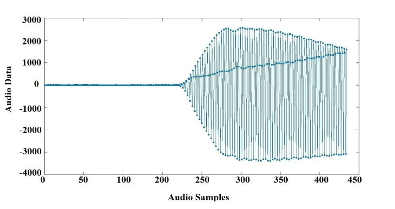
Some indoor events, like metal door slamming can generate high frequency noise entering
17 KHz frequency band and a preset threshold is not enough to filter out all environment
noise to detect audio signal’s arrival properly in a noisy environment. Moreover, the
low-power micro-controller in our system doesn’t have enough memory space and processing
power to process the entire audio pulse emitted from a smartphone. Therefore, the
correlation algorithm to determine the audio signal’s time difference of arrival [10] can’t
be deployed in our system.
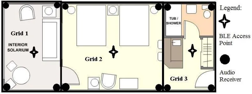
To address the problem, a smartphone app is designed in which the audio signal’s volume
increases continuously once the smartphone starts playing the audio pulse. Moreover, the
audio signal’s frequency is chosen to be one third of the sampling frequency so the received
audio data has 3 distinctly separated branches, i.e. upper, middle and lower branches. Fig.
4 shows the received audio signal’s waveform while Fig. 5 indicates the noise signal near
17 KHz, it can be seen that the designed audio pulse has its unique waveform, the difference
between upper and lower sides of audio data increases gradually after the starting point,
also the difference between either middle and upper or middle and lower sides increases
gradually. The audio receivers sample 60 consecutive audio data points after the first audio
data point exceeds a preset threshold. Then it checks to see if the received signal’s
waveform matches the reference signal stored in the memory to distinguish between the
desired audio signal and the environmental noise. In a very noisy environment, the desired
audio pulse’s waveform is degraded by noises at the 17 KHz band. To improve the audio
recognition rate in such environments, a moving average filter can be implemented to
smooth the received audio waveform. This method will increase the possibility of detecting
the transmitted audio signal since its pattern is based on a consecutively changing audio
16
Fig. 6. Sensortag used as an audio receiver.
17
3.4Experimental Validation
3.4.1 System Prototype
To conduct experimental measurements, a multiplatform application using Apache
Cordova framework was developed and installed on an Android based smartphone.
CC1350 Sensor tags from Texas Instruments (TI) were used as access points and audio
receivers. The sensor tag has a low-power micro-controller and works with a coin battery;
however it has powerful radio components which can support dual band wireless
communication at 868 MHz and 2.4GHz. Fig. 6 shows a sensor tag used in this work. The
firmware of sensor tags were modified to implement the filter and control modules using
TI development kit and Code Composer Studio platform.
The developed app can switch between the coarse positioning mode and the fine
positioning mode. In the fine positioning mode, the app utilizes smartphone’s speaker to
send short audio waves. Fig. 7 shows the screenshot of the developed smartphone app.
18
3.4.2 Experiment Setup
As shown in Fig. 8, 4 audio receivers are placed at known locations and a BLE access point
is placed at the middle. The experiment was conducted in a quiet environment and a noisy
environment. A laptop was placed near the audio receivers playing a recording to simulate
the environmental noise during the experiment.
Fig. 9. Experiment results in quiet environment
19
3.4.3 Experiment Result
The experiments were conducted in the second floor of Centre for Engineering Innovation
(CEI) building at the University of Windsor for both quiet and noisy environments.
For the quiet environment, users “x” and “y” coordinates were measured with the mean
absolute error of 1.64cm and 1.90cm respectively. In a noisy environment, the mean
absolute error for “x” and “y” coordinates elevates to 1.81 cm, 2.46 respectively. Fig. 9
shows the results in a quiet environment while Fig. 10 illustrates the results for a noisy
environment at different locations. It can be seen that in both noisy and quiet environment
the system can achieve centimeter level accuracy. The error for both x and y coordinates
falls below 3cm which indicate an overall good positioning accuracy.
3.5Conclusion
In this work a new indoor positioning systems for smartphones is presented. The proposed
system utilizes the received signal strength method for coarse positioning and uses
ultrasound for fine positioning. The proposed solution is optimized to reduce the power
consumption and the positioning error. Experimental measurement results using Bluetooth
Low Energy (BLE) tags indicate that the proposed localization system support a high
positioning accuracy in indoor environments with less than 3cm positioning error. The
implemented prototype system uses only BLE sensors and a smartphone app for
positioning to reduce the implementation costs.
3.6References
[1] J. Wendeberg, T. Janson, and C. Schindelhauer, "Self-Localization based on Ambient
Signals," Theoretical Computer Science, vol.453, pp.98-109, 2012.
[2] R. Mautz, "Indoor Positioning Technologies, " Habiliation Thesis, ETH Zurich, 2012.
[3] S. Murata et.al., "Accurate Indoor Positioning System using Near-Ultrasonic Sound
from a smartphone," Eighth International Conference on Next Generation, Oxford,
UK, 2014.
[4] F. Zaki, R. Rashidzadeh, "An Indoor Location Positioning Algorithm for Portable
Devices and Autonomous Machines," International Conference on Indoor Positioning
20
[5] "Audio Latency | Android NDK | Android Developers", Android Developers, 2017.
[Online]. Available:
https://developer.android.com/ndk/guides/audio/audio-latency.html. [Accessed 29 Sep. 2017].
[6] S. Lopes et al., "Accurate smartphone indoor positioning using a WSN infrastructure
and non-invasive audio for TDoA estimation," Pervasive and Mobile Computing, vol.
20, pp. 29-46, 2015.
[7] Y. Chan, K. Ho, "A simple and efficient estimator for hyperbolic location," IEEE
Transactions on Signal Processing, vol. 42(8), pp.1905-1915, 1994.
[8] Texas Instrument, CC1350 SimpleLink™ Ultralow-Power Dual-Band Wireless MCU
datasheet (Rev. A). Dallas, TX: 2016.
[9] "Dev.ti.com. CC13x0 RF User’s Guide — CC13x0 Proprietary RF User's Guide
1.01.00 documentation," [online] Available:
http://dev.ti.com/tirex/content/simplelink_cc13x0_sdk_1_30_00_06/docs/proprietary
-rf/html/cc13x0/index.html [Accessed 25 Feb. 2018].
[10] D. Hertz, "Time delay estimation by combining efficient algorithms and generalized
cross-correlation methods," IEEE Transactions on Acoustics, Speech, and Signal
Processing, vol. 34, pp.1-7, 1986.
[11] "Filtering and Smoothing Data- MATLAB & Simulink", Mathworks.com, 2018.
[Online]. Available: https://www.mathworks.com/help/curvefit/smoothing-data.html.
21
Chapter -4
An Indoor Location Estimation System with Fine and Coarse Positioning Modes
4.1Introduction
Location-aware applications and services are becoming more attractive than ever
particularly in indoor environments. GPS is widely used for location positioning however
GPS requires a line-of-sight connection between satellite transmitters and a receiver to
ensure positioning accuracy. Implementation of a GPS positioning system for indoor areas
is costly and unreliable [1]. Many cost-effective solutions have been developed for indoor
location estimation in recent years. Indoor positioning systems using received signal
strength emerged as low-cost systems achieving acceptable accuracy for many applications
[2-3]. Ultra-Wideband (UWB) technology [4] has also appeared for accurate and precision
indoor location estimation. However, UWB based systems are relatively costly. Location
estimation systems using audio signals support a high-accuracy positioning at low-cost.
Due to the widespread use of the cell phones, it is highly desired to design an indoor
positioning system that only requires smartphone at the user end.
The proposed system is developed to support off-line cell-phones for location positioning
without the need of internet connection. Such a positioning system preserves user privacy
as the location information is not shared online. In the proposed solution, Bluetooth Low
Energy (BLE) tags with sub-1GHz RF communication are used where the BLE nodes serve
as audio receivers. Their power-consumption is lower compared to systems using such
nodes as audio transmitters. The BLE nodes RF circuit operate in the sleep mode more than
50% of the time during the operation cycle, they are only activated in certain time points.
The Chirp Spread Spectrum (CSS) [2] technique is utilized in the audio mode to increase
the rage by reducing the effective noise level. Frequency modulated audio waves together
with a matched filter are used to support indoor location estimation over a wide range.
Moreover, an audio data clustering technique is used to enhance the system’s robustness
in dense multipath environments. A Non-Line-of-Sight (NLoS) identification method is
22
The rest of the paper is organized as follows: Section 3.2 covers the available solutions in
the literature, Section 3.3 presents an overview of the proposed system. Section 3.4
explains the details of the implemented DSP algorithms in the acoustic mode. Section 3.5
presents the simulation and the experimental measurement results. Section 3.6 summarizes
the results and presents the conclusions.
4.2Related Work
Acoustic indoor location positioning systems can be classified into two categories of (a)
systems using ultrasound and (b) systems using near-ultrasound. Cricket [12] and Active
Bat [13] are the two pioneering solutions using ultrasound to localize indoor positions
supporting centimeter level accuracy. However, they require custom-designed devices at
the user side and they do not support smartphone platforms. Beep [7] uses audible signals
with off-the-shelf devices, but it’s positioning accuracy is low due to the latency at the
sound card. Assist [6] utilizes near-ultrasound pulses generated by a smartphone speaker
to achieve centimeter level positioning accuracy, however, the use of Wi-Fi NTP protocol
for time synchronization increases power-consumption considerably [14]. Akkurate [8]
uses smartphones as audio receivers and supports a high positioning accuracy in 2D
environments, but the accuracy drops dramatically for a real-world 3D location positioning.
The BLE and ultrasound technologies have been used in ALPS [9] for localization in which
BLE nodes transmitter acoustic signals. An algorithm is also presented using machine
learning techniques to enhance the system’s robustness. Murata et al. proposed a high
accuracy near-ultrasound positioning system compatible with smartphones; however the
positioning accuracy drops considerably in noisy environments [10]. Pérez et al. proposed
an android application called LOCATE-US. The system implements code-division
multiple access (CDMA) technique to overcome the problems at the acoustic frequency
range between 20-22 KHz [11]. Zhang et al. proposed MAIDLOC and RA2LOC systems
along with DSP algorithms to enhance the system’s performance in noisy and dense
multipath locations [15]. They also presented an NLoS identification algorithm using
23
4.3System Overview
4.3.1 Dual Mode Positioning
The proposed system combines the RSSI-based positing algorithm developed by the
research team [17] for coarse positioning, and the acoustic positioning method for fine
positioning. The RSSI-based positioning method can achieve a meter-level accuracy while
the acoustic mode using the Time Difference of Arrival (TDoA) algorithm can achieve
centimeter level accuracy. The algorithms are implemented on BLE nodes and supported
by a smartphone app. The indoor area, as shown in Fig. 1, is divided into grids. Each grid
is covered with the BLE nodes consisting master and slave nodes which can receive audio
pulses and broadcast BLE packets. Mater nodes directly communicate with the smartphone
via BLE. Slave nodes receive inter-node commands from master nodes through sub-1 GHz
RF, this architecture consumes less power compared to the method in which each node
receives commands directly from the smartphone via BLE. In the coarse positioning mode,
BLE packets are transmitted by all BLE nodes and received by smartphones. The user
location in this mode is determined using the RSS based algorithm in [17]. In the acoustic
mode the smartphone transmits short audio pulses, the BLE nodes receive the pluses and
send the results back to the smartphone after applying a DSP algorithm. Acoustic mode
positioning is commonly affected by (a) indoor environment audio interferences and (b)
lack of line-of-sight propagation. The RSSI-based method is utilized to filter out outliers
from acoustic positioning mode as explained in section 3.4.5.
4.3.2 Multilateration Positioning
Smartphone operating systems have audio latency problems which leads to inaccurate
time-of-flight (ToF) estimation between audio receivers and smartphones. As a result
range-based positioning such as trilateration cannot be implemented. A range-free
positioning algorithm called multilateration is utilized to overcome the audio latency
problem. The difference between the Time-of-Arrivals (ToAs) at the audio receivers are
subtracted to get corresponding TDoAs, as shown in Fig. 2. The implemented BLE nodes
support sub-1 GHz RF signals used to synchronization all audio receiver nodes [18]. In a
room with audio receivers and a smartphone shown in Fig. 3, the user coordinates, 𝑥, 𝑦
24
2 2 2
2 2 22 ( 2) ( 2) 1 ( 1) ( 1) (2 1)
x x y y z z x x y y z z v t t (1)
2 2 2
2 2 23 ( 3) ( 3) 1 ( 1) ( 1) (3 1)
x x y y z z x x y y z z v t t (2)
2 2 2
2 2 24 ( 4) ( 4) 1 ( 1) ( 1) (4 1)
x x y y z z x x y y z z v t t (3)
2 2 2
2 2 25 ( 5) ( 5) 1 ( 1) ( 1) (5 1)
x x y y z z x x y y z z v t t (4)
25
Where 𝑡1 to 𝑡5 indicate the time-of-flight to different audio receivers plus the audio latency time. To cancel out the effect of audio latency, the time-difference of arrival is
determined. Each ToA is the summation of the time-of-flight and the audio latency time.
By pairwise subtracting the ToAs, the effect of unknown latency time is nullified. If we
assume the first audio receiver is positioned at the origin, we can use the linear least square
algorithm to achieve an optimal solution [19]. We have the following matrixes:
Fig. 2. Time-of-Arrivals (ToAs) for two nodes and the corresponding Time Difference of Arrival (TDoA).
26
21 2 2 2
31 3 3 3
41 4 4 4
51 5 5 5
A
d
x
y
z
d
x
y
z
d
x
y
z
d
x
y
z
2 2 2 21 2 2 3 31 2 2 4 41 2 2 5 511
b=
2
b
d
b
d
b
d
b
d
X
y=
x
y
z
X=
x
y
z
(5)Wheredijv(titj),
2 2 2 2
i i i i
b x y z and ‖𝐗‖ is the Euclidean vector norm [19]. We then use the linear least squares to achieve the optimal estimation of smartphone coordinate as
follows:
1
(A A) A b
T Ty
(6)The above algorithm can provide accurate positioning results. There are also non-linear
least square algorithms such as Gauss-Newton, Steepest Descent and
Levenberg-Marquardt proposed to further improve the positioning accuracy [17]. These non-linear
algorithms first expand equations (1)-(4) at the point 𝐗, approximate these equations with
the 1st order Taylor-series, then they use 𝐗as the initial guess to implement the iterative
process to get the final estimated positions. However, these algorithms require the initial
point 𝐗to be close to the real position, otherwise the iterative process may fail to converge
[21]. Using the above-mentioned linear least square method, the estimated z coordinates
are often far away from their real values. Though the estimation error in the z coordinate
will not corrupt the horizontal positioning performance, the above-mentioned algorithms
may fail to work. Moreover, an iterative process on a smartphone app may take a long time
to converge, so instead of the non-linear least square methods we only utilize linear least
square method with an optimal node placement, which will be discussed later. For accurate
27
generated by pair-wise subtracting of ToAs. Moreover, an accurate inter-node time
synchronization is vital to eliminate the added latency by the nodes.
4.4ToA Estimation
4.4.1 Linear Frequency Modulated Chirp & Matched Filtering
Linear Frequency Modulated (LFM) Chirp pulse is a sinusoidal wave pulse whose
frequency,𝑓, increases or decreases linearly with time, 𝑓 = 𝑓0+ 𝑘𝑡. The signal in the time
domain can be represented by:
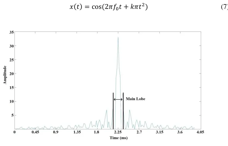
𝑥(𝑡) = cos(2𝜋𝑓0𝑡 + 𝑘𝜋𝑡2) (7)
Where 𝑓0 is the initial frequency and 𝑘 is the frequency changing rate, in our system the
signal’s length is 150ms, the initial frequency 𝑓0 is 15kHz and the frequency changing rate
𝑘 is 20kHz/s, the transmitted signal is an up-chirp with the bandwidth of 3KHz.
We used a matched filter [22] to determine the chirp’s ToA. Ideally, an audio signal,𝑥(𝑡),
received as:
𝑦(𝑡) = {𝑥(𝑡 − 𝑇𝑇𝑜𝐴)𝑇𝑇𝑜𝐴 ≤ 𝑡 ≤ 𝑇′
0𝑜𝑡ℎ𝑒𝑟𝑤𝑖𝑠𝑒 (8)
28
Where 𝑇′ is the chirp’s ending time. We cross-correlate the received signal with the
reference signal, this is essentially an auto-correlation. The cross-correlation function can
be written as:
𝑐(𝜏) = ∫ 𝑦(𝑡) ∙0𝑇 𝑅𝑒𝑓(𝑡 − 𝜏)𝑑𝑡𝜏 ≥ 0 (9)
Where 𝑦(𝑡)is the received signal, 𝑅𝑒𝑓(𝑡) is the reference chirp signal and 𝑇 is the chirp
signal’s length. The cross-correlation result can be written as [23]:
𝑐(𝑡) = √𝐵𝑇 ∙ 𝑠𝑖𝑛𝑐[𝜋𝐵(𝑡 − 𝑇𝑇𝑜𝐴)] ∙ 𝑐𝑜𝑠[2𝜋𝑓0(𝑡 − 𝑇𝑇𝑜𝐴)] (10) Where 𝐵 is the chirp signal’s bandwidth, 𝑐(𝑡) reaches its peak at 𝑡 = 𝑇𝑇𝑜𝐴 which is the arrival time of the transmitted audio signal.
The energy of the whole received chirp pulse is compressed into the main lobe of 𝑐(𝑡) after
the cross-correlation, as shown in Fig. 4. Compared to the original sinc function, its
amplitude is increased by the ratio of √𝐵𝑇, in our system this ratio is about 21. Sound energy attenuates dramatically as the transmission range increases, however with chirp
signal and a matched filter, cross-correlation peak corresponding to the ToA point can still
be detected even after a propagation range of 20m. Moreover, a chirp signal has a good
noise-resistance performance and Doppler effect tolerance. As a result, the combination of
a chirp signal and a matched filter is well-suited for ToA estimation of acoustic signals.
In the proposed solution, the algorithm to determine the ToAs runs on the BLE nodes. We
compute the cross-correlation in the frequencydomain instead of the time domain to reduce
the power consumption. The cross-correlation function can be written as:
𝑐(𝑡) = 𝐼𝑅𝐹𝐹𝑇(𝑌 ∙ 𝑅𝐸𝐹∗) (11)
Where 𝐼𝑅𝐹𝐹𝑇 is the inverse real Fourier transform. 𝑌 is the real Fourier transform of the
received signal 𝑦(𝑡), and 𝑅𝐸𝐹is the Fourier transform of the reference chirp signal 𝑅𝑒𝑓(𝑡),
𝑅𝐸𝐹∗ is the conjugate of 𝑅𝐸𝐹 . It takes about 20ms to calculate the cross-correlation for
16384 sample points in the frequency domain, which supports real-time location estimation
29
4.4.2 Indoor Acoustic Environment Modeling
In an ideal case, the received audio signal can be represented by:
1
( )
(
)
( )
N i i iy t
a x t
n t
(12)Where 𝑁 is the number of propagation paths, 𝑎𝑖 indicates different paths’ fading
coefficients and 𝜏𝑖 represents different paths’ time delay and 𝑛(𝑡) is white-noise. The
signal from the direct propagation path takes the shortest transmission time. The received
signal from all paths can be considered as the superposition of replicas of 𝑥(𝑡) with
different time delays and energy attenuations. The direct path signal has the strongest
energy contribution compared to signals from other paths creating the highest
correlation-peak. There is no correlation between the forwarded chirp signal and white noise. Thus the
highest correlation-peak is not masked by the audio noise in the environment as long as the
noise is not too strong compared to the signal.
In a real-world scenario, the received signals are not the exact replicas of the reference
chirp signal 𝑥(𝑡). The performance parameters of the propagation channels may vary
significantly. An acoustic channel’s frequency response is ideally considered flat for all
in-band frequencies and represented by (13).
𝐻(𝜔) = {1𝜔1 ≤ 𝜔 ≤ 𝜔2
0𝑜𝑡ℎ𝑒𝑟𝑤𝑖𝑠𝑒 (13)
In a real case, the in-band frequency response is not flat and the received chirp signal may
get distorted as indicated in Fig.5. Since the chirp signal’s frequency changes linearly with time, the corresponding acoustic channel’s frequency response is uneven for all in-band
frequencies. The acoustic channel is commonly a smooth curve in the frequency domain.
Thus, it can be expressed by a polynomial using Taylor-series. As a result, for every
location in a room, no matter how different the acoustic channels are, the frequency
responses can be always written as:
𝐻(𝜔) = {𝑎𝑛𝜔𝑛 + 𝑎𝑛−1𝜔𝑛−1+ ⋯ + 𝑎0𝜔1 ≤ 𝜔 ≤ 𝜔2
30
As mentioned above, the cross-correlation algorithm can be performed in the frequency
domain. Therefore, for an arbitrary acoustic channel, the cross-correlation function of (11)
can be modified as:
𝑐(𝑡) = 𝐼𝑅𝐹𝐹𝑇(𝐻 ∙ 𝑌 ∙ 𝑅𝐸𝐹∗) (15) It can be expanded as:
𝑐(𝑡) = 𝐼𝑅𝐹𝐹𝑇(𝑎𝑛𝜔𝑛) ∗ 𝐼𝑅𝐹𝐹𝑇(𝑌 ∙ 𝑅𝐸𝐹∗) + 𝐼𝑅𝐹𝐹𝑇(𝑎𝑛−1𝜔𝑛−1)
∗ 𝐼𝑅𝐹𝐹𝑇(𝑌 ∙ 𝑅𝐸𝐹∗) + ⋯ + 𝑎
0∙ 𝐼𝑅𝐹𝐹𝑇(𝑌 ∙ 𝑅𝐸𝐹∗) (16)
Where 𝐼𝑅𝐹𝐹𝑇 is the inverse real Fourier transform. The inverse Fourier transform of 𝜔𝑛
is the 𝑛𝑡ℎderivative of the Dirac delta function which will not generate an output after convolution with the received signal and the reference signal. Therefore, the non-ideal
frequency response of the propagation channel will not affect the final cross-correlation
output.
31
Due to multipath effects, in some indoor environments, as shown in Fig. 6, the direct path
signal’s correlation peak is not the highest. Moreover, in some cases the Line-of-Sight
(LoS) channel cannot be guaranteed. However, the signal from multi-paths takes longer
propagation time compared to the direct path. As a result, we can conclude that in an indoor
environment, as long as (a) there exists a direct path between the smartphone speaker and
the audio receiver and (b) the SNR is above a certain level, no matter how severe the
multi-path effects are, the first detectable correlation peak location is always the ToA of the
transmitted audio signal. If the LoS condition cannot be guaranteed and the whole received
signal only consists of NLoS path signals, the first correlation peak may not represent the
ToA. The NLoS case is discussed in the following section.
4.4.3 Noise Filtering
Environmental noise is an important factor in an acoustic channel. There are many high-
frequency signals generated by different activities such as the door slamming, high-heeled
shoes hitting the ground and tableware collisions. The chirp signal in our system sweeps
from 15KHz to 18KHz. A window-based band-pass filter with the passband from 15KHz
to 18KHz is implemented to filter out the out-of-band noise. However, there is still in-band
noise added to the received signal. Using a matched-filtering approach, the received signal
generates outputs only when it matches the reference signal. Pearson correlation coefficient
32
[24] can be used to measure the similarity between the received and the reference signals.
It is defined as:
𝜌(𝐴, 𝐵) = 𝑐𝑜𝑣(𝐴,𝐵)𝜎
𝐴𝜎𝐵 (18)
Where 𝐴 and 𝐵 are the two signals, 𝑐𝑜𝑣(𝐴, 𝐵) is the covariance of 𝐴 and 𝐵, 𝜎𝐴 is the
standard deviation of 𝐴 and 𝜎𝐵 is the standard deviation of 𝐵.
We sampled noise in different indoor environments and computed their Pearson correlation
coefficients with a reference signal to estimate the possibilities that they could alter the
matched filter’s output. A correlation coefficient between -0.1 to +0.1 indicates a
negligible correlation [25]. The tests results in Table 1, indicate that in 99.9% cases the
correlation coefficients are between -0.1 to +0.1. As a result, it is concluded that the
environmental audio noise is unlikely to correlate with a reference chirp signal to alter the
matched filter’s output.
To further filter out the noise, we used a threshold-based method. We set the threshold
according to the average positive amplitude of the cross-correlation output. We first
computed this average value and then set the threshold to be four times of the average
value. Fig. 7 shows the calculated threshold for the propagation channel. It can be seen that
the noise in the cross-correlation output is mainly below the threshold. The solution using
a chirp signal with a matched filter presents a good performance in noisy environments.
TABLE I. NOISECORRELATIONCOEFFICIENTSTESTS
Scenarios No or Very Weak Correlation
Shopping Mall 99.97%
Restaurant 99.89%
University Hallway 99.96%
Indoor Parking Lot 99.99%