University of Windsor University of Windsor
Scholarship at UWindsor
Scholarship at UWindsor
Electronic Theses and Dissertations Theses, Dissertations, and Major Papers
2013
Advancement of Shock-wave Induced Spraying Process through
Advancement of Shock-wave Induced Spraying Process through
the Study of Gas and Particle Flow Fields
the Study of Gas and Particle Flow Fields
Mohammad Karimi Esfahani University of Windsor
Follow this and additional works at: https://scholar.uwindsor.ca/etd
Recommended Citation Recommended Citation
Karimi Esfahani, Mohammad, "Advancement of Shock-wave Induced Spraying Process through the Study of Gas and Particle Flow Fields" (2013). Electronic Theses and Dissertations. 4715.
https://scholar.uwindsor.ca/etd/4715
This online database contains the full-text of PhD dissertations and Masters’ theses of University of Windsor students from 1954 forward. These documents are made available for personal study and research purposes only, in accordance with the Canadian Copyright Act and the Creative Commons license—CC BY-NC-ND (Attribution, Non-Commercial, No Derivative Works). Under this license, works must always be attributed to the copyright holder (original author), cannot be used for any commercial purposes, and may not be altered. Any other use would require the permission of the copyright holder. Students may inquire about withdrawing their dissertation and/or thesis from this database. For additional inquiries, please contact the repository administrator via email
Advancement of Shock-wave Induced Spraying Process through
the Study of Gas and Particle Flow Fields
by
Mohammad Karimi Esfahani
A Dissertation
Submitted to the Faculty of Graduate Studies
through Mechanical, Automotive and Material Engineering in Partial Fulfillment of the Requirements for
the Degree of Doctor of Philosophy at the University of Windsor
Windsor, Ontario, Canada 2012
978-0-494-79150-9 Your file Votre référence
Library and Archives
Canada Bibliothèque etArchives Canada Published Heritage
Branch
395 Wellington Street Ottawa ON K1A 0N4 Canada
Direction du
Patrimoine de l'édition
395, rue Wellington Ottawa ON K1A 0N4 Canada
NOTICE:
ISBN:
Our file Notre référence 978-0-494-79150-9 ISBN:
The author has granted a
non-exclusive license allowing Library and Archives Canada to reproduce, publish, archive, preserve, conserve, communicate to the public by
telecommunication or on the Internet, loan, distrbute and sell theses
worldwide, for commercial or non-commercial purposes, in microform, paper, electronic and/or any other formats.
The author retains copyright ownership and moral rights in this thesis. Neither the thesis nor substantial extracts from it may be printed or otherwise reproduced without the author's permission.
In compliance with the Canadian Privacy Act some supporting forms may have been removed from this thesis.
While these forms may be included in the document page count, their removal does not represent any loss of content from the thesis.
AVIS:
L'auteur a accordé une licence non exclusive permettant à la Bibliothèque et Archives Canada de reproduire, publier, archiver, sauvegarder, conserver, transmettre au public par télécommunication ou par l'Internet, prêter, distribuer et vendre des thèses partout dans le monde, à des fins commerciales ou autres, sur support microforme, papier, électronique et/ou autres formats.
L'auteur conserve la propriété du droit d'auteur et des droits moraux qui protege cette thèse. Ni la thèse ni des extraits substantiels de celle-ci ne doivent être imprimés ou autrement
reproduits sans son autorisation.
Conformément à la loi canadienne sur la protection de la vie privée, quelques formulaires secondaires ont été enlevés de cette thèse.
ADVANCEMENT OF SHOCK-WAVE INDUCED SPRAYING PROCESS THROUGH THE STUDY OF GAS AND PARTICLE FLOW FIELDS
by Mo Karimi
APPROVED BY:
_________________________________ Dr. André G. McDonald
Mechanical Engineering, University of Alberta
_________________________________ Dr. J. Villafuerte
Industrial Advisor, CenterLine (Windsor) Limited
_________________________________ Dr. R. Carriveau
Civil and Environmental Engineering
_________________________________ Dr. R. Barron
Mechanical, Automotive and Materials Engineering
_________________________________ Dr. N. Zamani
Mechanical, Automotive and Material Engineering
_________________________________ Dr. B. Jodoin, Co-Advisor
Mechanical Engineering, University of Ottawa
_______________________________ Dr. G. Rankin, Co-Advisor Mechanical, Automotive and Material
Engineering
_________________________________ Dr. K. Tepe, Chair of Defense Electrical and Computer Engineering
iii
Declaration of Co-Authorship / Previous Publication
I. Co-Authorship Declaration
I hereby declare that this dissertation incorporates the outcome of research
undertaken under the co-supervision of Dr. G. Rankin, University of Windsor, and Dr. B.
Jodoin, University of Ottawa, with Dr. J. Villafuerte, CenterLine (Windsor) Limited as
Industrial Advisor. In all cases, I certify that I am the principal author and have had a
major role in the preparation and writing of the manuscripts.
I am aware of the University of Windsor’s Senate Policy on Authorship and I
certify that I have properly acknowledged the contribution of other researchers to my
dissertation.
I certify that, with the above qualifications, this dissertation, and the research to
iv II. Declaration of Previous Publication
This dissertation includes two original papers that have been previously published
in peer-reviewed journals as indicated below:
Publication Title / Full
Citation
Co-authors’ Nature and Extent of
Contribution
Publication,
Copyright Status
M. Karimi, B. Jodoin and G.
Rankin, Shockwave Induced
Spraying Process: Effect of
Parameters on Coating
Performance. International
Thermal Spray Conference
and Exposition, Seoul, South
Korea (2013).
Dr. Jodoin and Dr. Rankin are
providing supervisory and advisory
role in preparing the manuscript.
Abstract and presentation: abstract accepted, manuscript underway. Authors still hold copyright.
M. Karimi, B. Jodoin and G.
Rankin, Influence of Spray
Variables on the Performance
of the Shockwave Induced
Spraying Process. North
American Cold Spray
Conference, Seattle, WA,
USA (2013).
Dr. Jodoin and Dr. Rankin provided
supervisory and advisory role in
preparing the manuscript.
Abstract and
presentation:
abstract accepted.
Authors hold
v M. Karimi, G. W. Rankin
and B. Jodoin, Shock-wave
induced spraying: Gas and
particle flow and coating
analysis. Surface and
Coatings Technology (2012),
207, 435-442.
Dr. Jodoin and Dr. Rankin provided
supervisory and advisory role in
preparing the manuscript.
Moreover, Dr. Jodoin provided a
major portion of the Introduction,
where a survey of the technology is
presented. Although this formed the
structure of Section 1.1
(‘Technology Background’) of this
dissertation, it has been
significantly expanded by me.
Journal article:
published. Generic
permission
included in
Appendix A.
M. Karimi, B. Jodoin and
G.W. Rankin, Shockwave
Induced Spraying Process:
Prediction of Coating
Formation in
Shockwave-Induced Spray Process
Through Modeling.
International Thermal Spray
Conference and Exposition,
Houston, TX, USA (2012).
Dr. Jodoin and Dr. Rankin are
providing supervisory and advisory
role in preparing the manuscript.
vi M. Karimi, B. Jodoin and G.
Rankin, Shockwave Induced
Spraying: Modeling and
Physics of a New Spray
Process. Journal of Thermal
Spray Technology (2011),
20, 866-881.
Dr. Jodoin and Dr. Rankin provided
supervisory and advisory role in
preparing the manuscript.
Journal article:
published. Generic
permission
included in
Appendix A.
M. Karimi, B. Jodoin, G.W.
Rankin. Shock-wave Induced
Spraying: Modeling and
Analysis. North American
Cold Spray Conference,
Windsor, ON, Canada
(2011).
Dr. Jodoin and Dr. Rankin provided
supervisory and advisory role in
preparing the manuscript.
Abstract,
presentation and
poster. Authors
hold copyright.
M. Karimi, B. Jodoin and
G.W. Rankin. Shock-wave
Induced Spraying: Modeling
and Physics of a New Spray
Process. International
Thermal Spray Conference
and Exposition, Hamburg,
Germany (2011).
Dr. Jodoin and Dr. Rankin are
providing supervisory and advisory
role in preparing the manuscript.
Manuscript and
poster. Generic
permission
included in
vii M. Karimi, G.W. Rankin and
B. Jodoin. Simulation and
Post-processing of Transient
Compressible Flow in a Long
Tube. CFD Society of
Canada Conference,
Montreal, QC, Canada
(2011).
Dr. Jodoin and Dr. Rankin are
providing supervisory and advisory
role in preparing the manuscript.
Manuscript and
presentation.
Authors hold
copyright.
M. Karimi, B. Jodoin, G.W.
Rankin. Shock-wave Induced
Spraying: Modeling and
Analysis. North American
Cold Spray Conference,
Montreal, QC, Canada
(2010).
Dr. Jodoin and Dr. Rankin provided
supervisory and advisory role in
preparing the manuscript.
Abstract and
poster. Authors
hold copyright.
I certify that I have obtained written permission from the copyright holders to
include the above published materials in my dissertation. An image of these written
permissions is included in Appendix A. I certify that the above material describes work
completed during my registration as a graduate student at the University of Windsor.
I declare that to the best of my knowledge, my dissertation does not infringe upon
anyone’s copyright nor violate any proprietary rights and that any ideas, techniques,
viii dissertation, published or otherwise, are fully acknowledged in accordance with standard
referencing practices. Furthermore, to the extent that I have included copyrighted
material that surpasses the bounds of fair dealing within the meaning of the Canada
Copyright Act, I certify that I have obtained a written permission from the copyright
owners to include such material(s) in my dissertation.
I declare that this is a true copy of my dissertation, including any final revisions,
as approved by my defense committee and the Office of Graduate Studies, and that this
dissertation has not been submitted for a higher degree to any other university or
ix
Abstract
This research advances the knowledge of the working principles of the
Shock-wave Induced Spraying Process (SISP), a thermal spray material deposition technique.
Pulses created by a fast acting valve pass through a heated line increasing energy content
and interacting with metered batches of heated or non-heated powder introduced into the
line. The powder is accelerated to high velocities before bonding to the substrate upon
impact.
Advantages over other cold spray processes include cost savings and a more
effective transfer of thermal energy to the powder. The shock-wave occurring near the
substrate in other cold spray processes is avoided.
The SISP flow field is resolved by using a computational model. The
two-dimensional model accounts for the valve, gas heater, a tapered nozzle at the tip of the
device, and pre-heating of the powder. It is implemented with a commercial
computational fluid dynamics code. Comparisons are made with one-dimensional
predictions, and measurements of pressure and temperature. Particle flow predictions are
validated using particle velocity and adhesion measurements.
A flow region of both high temperature and velocity gas, favorable to material
deposition, forms which is not present in comparable steady-state cold spray processes.
x speed and temperature of this region. Using helium results in greater energy levels but for
shorter periods of time. This indicates the need for a powder feeder which places particles
in the flow at correct instants and durations of time.
The effects of particle flow parameters on system performance are examined. It is
found that the device must be operated at very high main heater and powder heater
temperatures: 900 °C and 700 °C respectively to achieve a coating with stainless steel
using nitrogen as the driving gas. It is also shown that a heater length range of 0.9 m to
1.4 m results in the greatest likelihood of achieving a coating. A higher spray frequency
yields more uniform coating at the expense of performance. Powder heating becomes
effective at temperatures above 300 °C, especially with aluminum compared to copper
xi
Dedication
xii
Acknowledgements
I hereby extend my warm thanks to Dr. Rankin and Dr. Jodoin for their continual
guidance, support and advice during the period of this project. This was essential to the
completion of this work. My sincere thanks also goes to Dr. Villafuerte who was my
industrial advisor and provided invaluable input.
I also acknowledge support and advice from Dr. Barron. He provided technical
guidance through his two courses in computational fluid dynamics as well as his
coaching of a course project that created the basis for this study. More importantly, he
has set a golden standard in professionalism and passion to his work and his students,
which has been a source of aspiration to me.
I also acknowledge motivation and encouragement that I received from Dr.
Zamani when making important professional decisions. Additionally, Eric Michaud and
Doug Matton of CenterLine Windsor Limited provided valuable technical input and
support in the form of equipment when needed. My thanks go to Michael Beneteau of
CenterLine Windsor Limited for allowing me the flexibility to pursue my academic
aspiration while still staying affiliated with the company, affording me a unique
opportunity to enhance my abilities in both academia and industry, and helping me meet
xiii The research presented here is funded by NSERC through a few different grants,
namely, a ‘Alexander Graham Bell’ scholarship held by me at University of Windsor,
NSERC Discovery grants held by Dr. Rankin and Dr. Jodoin, as well as a NSERC - Idea
to Innovation (I2I) grant held by Dr. Jodoin. The authors gratefully acknowledge this
support.
Last but not least, I give my best regards and heartfelt thanks to my wife Hoda.
She has been patient with me while I was working long hours each day, and encouraging
me to pursue my wildest dreams fearlessly.
xiv
Table of Contents
Declaration of Co-Authorship / Previous Publication ... iii
Abstract ... ix
Dedication ... xi
Acknowledgements ... xii
List of Tables ... xviii
List of Figures ... xix
Nomenclature: List of Symbols and Subscripts ... xxv
Chapter 1. Introduction ... 1
1.1 Technology Background ... 1
1.2 Shock-wave Induced Spray Process ... 10
1.3 Bonding Mechanism in Kinetic Spraying ... 12
Chapter 2. Literature Review and Objectives ... 15
2.1 Previous Studies ... 15
2.2 Overview of Flow Physics ... 19
2.3 Objectives ... 24
2.4 Contents of Dissertation ... 25
xv
3.1 Computational Gas Dynamic Model ... 27
3.1.1 Problem Statement ... 28
3.1.2 Assumptions ... 28
3.1.3 Governing Equations ... 33
3.1.4 Grid Considerations ... 35
3.1.5 Boundary Conditions ... 39
3.1.6 Initial Conditions ... 40
3.2 Discrete Phase Model ... 40
3.3 Solver Settings... 43
Chapter 4. Numerical Experiments, Verification and Validation ... 47
4.1 Stage One: Generic Gas Flow ... 47
4.1.1 Model Conditions ... 48
4.1.2 Model Verification ... 50
4.1.3 Presentation of Results ... 55
4.1.4 Model Validation ... 58
4.2 Stage Two: Representative Gas Flow ... 62
4.2.1 Model Conditions ... 63
4.2.2 Model Validation ... 64
4.3 Stage Three: Discrete Phase ... 67
xvi
4.3.2 Model Validations ... 68
Chapter 5. Results and Discussion ... 71
5.1 Stage One: Gas Phase - Simplified Model ... 71
5.1.1 Effect of Gas Supply Pressure and Temperature ... 72
5.1.2 Effect of Gas Type ... 80
5.1.3 Summary of Stage One: Gas Phase - Simplified Model ... 85
5.2 Stage Two: Gas Phase - Representative Geometry ... 87
5.2.1 Results of Stage Two: Gas Phase - Representative Geometry ... 88
5.2.2 Summary of Stage Two: Gas Phase - Representative Geometry ... 92
5.3 Stage Three: Discrete Phase ... 92
5.3.1 Presentation of Results ... 93
5.3.2 Experimental Work and Comparison with Discrete Phase Predictions ... 97
5.3.3 Summary of Stage Three: Discrete Phase Model in Representative Geometry ... 100
Chapter 6. Case Studies ... 102
6.1 Coating with Stainless Steel Powder ... 102
6.2 Effect of Heater Length ... 103
6.3 Effect of Process Frequency ... 108
6.4 Effect of Powder Heating Temperature ... 110
xvii
Chapter 7. Conclusion ... 116
Chapter 8. Recommendation for Future Work ... 121
References ... 123
Appendix A Written Permission from the Copyright Holders ... 130
Appendix B Profile for Valve Motion and Heater Temperature ... 138
Appendix C User-Defined Function to Model Heat Transfer under High-Mach-Number Gas-Particle Relative Flow ... 144
Appendix D Effect of Radial Location of Particle Injection ... 147
Appendix E Journal File for Extracting Data on the Centerline ... 153
Appendix F MATLAB Codes to Generate x-t Contours of Flow Variables ... 155
Appendix G MATLAB Codes to Generate Time History Plots of Flow Variables .. 159
Appendix H MATLAB Code to Generate x-t Contours and Extract Time History Data of Particle Variables ... 164
xviii
List of Tables
Table 1: Different categories of thermal spraying and their main properties. ... 10
Table 2: Geometrical features of the device modeled. ... 47
Table 3: Simulation conditions considered in the Stage One of the study. ... 49
Table 4: Combinations of interest for simulation conditions for this study. ... 50
Table 5: Summary of various grids used in the grid sensitivity study. ... 51
Table 6: Comparison of simulation results with one-dimensional solution. ... 59
Table 7: Parameters used to calculate critical velocity. ... 95
Table 8: Maximum value of V/Vcr and time per cycle during which this value falls between 1.0 and 2.0, in comparison with experimental values of deposition efficiency, for various particle materials and sizes... 98
xix
List of Figures
Figure 1: Schematic of the plasma spray process (top) and a plasma spray torch (bottom)
during a spray process - courtesy of Gordon England [8]. ... 3
Figure 2: Schematic of the arc spray process (top) and an arc spray device (bottom)
during a spray process - courtesy of Gordon England [8]. ... 4
Figure 3: Schematic of the HVOF process (top) and a HVOF device (bottom) during a
spray process - courtesy of Gordon England [8]. ... 5
Figure 4: A schematic diagram of the cold spray process - courtesy of Gordon
England [8]... 7
Figure 5: Schematic of the Shock-wave Induced Spraying Process Device ... 11
Figure 6: Beta version of the first SISP device, named Waverider™. Picture courtesy of
SST, a division of CenterLine (Windsor) Limited [48]. ... 17
Figure 7: Consecutive images depicting the intended working principle in the
Shock-wave Induced Spraying Process... 20
Figure 8: Schematic of the SISP spray device through one pulse spray cycle. Reproduced
with permission [39]. ... 21
Figure 9: Schematic of the one-dimensional model. ... 22
Figure 10: Theoretical instantaneous values of gas speed and temperature just prior to the
departure of the shock-wave from the spray device. Reproduced with permission [39]. . 23
Figure 11: A generic schematic of the flow region... 28
Figure 12: Picture and a CAD representation of the rotary-style valve used in the SISP
xx Figure 13: Left: a heating tube (in coiled form) during a heating process with gas flow,
Right: comparison of measured temperature values along the heater tube with a linear
approximation proposed for use as boundary condition in the simulation. ... 32
Figure 14: Mesh, near the valve ball (left) and near the tube exit and substrate (right). .. 35
Figure 15: Adapted grid superimposed on contours of static pressure (Pa) at t = 0.2 m. A
14-mm-long portion of the tube, 110 mm downstream of valve. ... 37
Figure 16: Dynamic meshing - layering method ... 38
Figure 17: Mesh near the valve ball (left), zoomed in with the valve closed (center) and in
the process of opening (right). ... 39
Figure 18: Schematic of the flow region used at Stage One. ... 48
Figure 19: Values of static temperature and axial velocity along the centerline of the
device at two time instants using grids with 3, 5 and 7 cells along the radius ... 52
Figure 20: Values of static temperature (top) and axial velocity (bottom) at three solution
times using three different time step values. ... 54
Figure 21: Values of velocity magnitude (left) and static temperature (right) along the
spray device centerline at the beginning of the first four pulses... 55
Figure 22: Sequential contours of static temperature at 0 ms to 4 ms. Air, 2 MPa, room
temperature. ... 56
Figure 23: Contours of static temperature (K) in space-time domain – Air, 2 MPa, no
heat. ... 57
Figure 24: Comparison of density values (in kg/m3) obtained from current CFD
simulation (left) with validated one-dimensional model (right). Air, 2 MPa supply
xxi Figure 25: Schematic of the flow region used at Stage Two. ... 63
Figure 26: Comparison of time-history of wall pressure at two locations along the spray
tube between the experiment and the simulation: 1- immediately after the valve, 2- at the
powder injection location. ... 65
Figure 27: Effect of stroke length on prediction of pressure, and comparison with
experimentally measured pressure values. ... 66
Figure 28: Experimentally measured temperature values overlaid on predictions from the
simulation. ... 67
Figure 29: Typical location of particle injection site with reference to the valve and
nozzle exit. ... 68
Figure 30: DPV-2000 particle analysis device by Tecnar Inc. ... 69
Figure 31: Comparison of measured and calculated particle speed at the exit of the SISP
device for aluminum (top), copper (center) and stainless steel 316 (bottom) particles. ... 70
Figure 32: Effect of supply pressure and temperature on static pressure (Pa). Supply
temperature and pressure values of ambient and 1 MPa (left), ambient and 2 MPa
(middle) and 300 °C and 2 MPa (right). ... 73
Figure 33: Effect of supply pressure and temperature on Mach number. Supply
temperature and pressure values of ambient and 1 MPa (left), ambient and 2 MPa
(middle) and 300 °C and 2 MPa (right). ... 73
Figure 34: Effect of supply pressure (top) and temperature (bottom) on gas speed and
Mach number in zone 2, with the assumption of fully-recovered temperature and no
xxii Figure 35: Effect of supply pressure and temperature on axial velocity (m/s). Supply
temperature and pressure values of ambient and 1 MPa (left), ambient and 2 MPa
(middle) and 300 °C and 2 MPa (right). ... 76
Figure 36: Effect of supply pressure and temperature on static temperature (K). Supply
temperature and pressure values of ambient and 1 MPa (left), ambient and 2 MPa
(middle) and 300 °C and 2 MPa (right). ... 78
Figure 37: Effect of supply pressure and temperature on total temperature (K). Supply
temperature and pressure values of ambient and 1 MPa (left), ambient and 2 MPa
(middle) and 300 °C and 2 MPa (right). ... 80
Figure 38: Effect of gas type on static pressure (Pa). Gas type of air (left) and helium
(right). ... 81
Figure 39: Effect of gas type on axial velocity (m/s). Gas type of air (left) and helium
(right). ... 82
Figure 40: Effect of gas type on Mach number. Gas type of air (left) and helium (right).83
Figure 41: Effect of gas type on static temperature (K). Gas type of air (left) and helium
(right). ... 84
Figure 42: Effect of gas type on total temperature (K). Gas type of air (left) and helium
(right). ... 85
Figure 43: Contours of (a) pressure (Pa), (b) axial velocity (m/s), (c) temperature (K) and
(d) total temperature (K) for a typical spray device. ... 89
Figure 44: Contours of (a) pressure (Pa), (b) axial velocity (m/s), (c) temperature (K) and
xxiii Figure 45: Contours of particle characteristics upon impacting on the substrate for
20-micron stainless steel 316 particles initiated at various locations and times in the domain:
(a) speed (m/s), (b) temperature (K), (c) critical velocity (m/s) and (d) critical velocity
ratio V/Vcr. ... 94
Figure 46: Calculated values of V/Vcr for particles of various sizes and materials injected
at typical location and various times. ... 96
Figure 47: Effect of increased heater temperature setting and powder preheating on the
fate of powder particles upon reaching the substrate. ... 103
Figure 48: Values of V/Vcr as a function of injection time for aluminum (top), copper
(middle) and stainless steel (bottom) powder particles. ... 105
Figure 49: Effect of frequency on values of V/Vcr for aluminum (top), copper (middle)
and stainless steel (bottom) powder feedstock. ... 109
Figure 50: Effect of powder preheat temperature setting on the value of V/Vcr for particles
of (top) aluminum, (middle) copper, and (bottom) stainless steel ... 111
Figure 51: Effect of powder preheat temperature setting on the value of V/Vcr for particles
of (top) aluminum, (middle) copper, and (bottom) stainless steel ... 112
Figure 52: Effect of powder loading on the value of V/Vcr for particles of (top) aluminum,
(middle) copper, and (bottom) stainless steel. ... 115
Figure D1: Speed (left) and temperature (right) of 20-micron aluminum particles upon
impacting on substrate, initiated at 0.0R (top), 0.5R (center), and 0.8R (bottom) ... 147
Figure D2: Speed (left) and temperature (right) of 20-micron copper particles upon
xxiv Figure D3: Speed (left) and temperature (right) of 20-micron stainless steel particles upon
impacting on substrate, initiated at 0.0R (top), 0.5R (center), and 0.8R (bottom) ... 149
Figure D4: V/Vcr values for 20-micron aluminum particles upon impacting on substrate,
initiated at 0.0R (top), 0.5R (middle), and 0.8R (bottom) ... 150
Figure D5: V/Vcr values for 20-micron copper particles upon impacting on substrate,
initiated at 0.0R (top), 0.5R (middle), and 0.8R (bottom) ... 151
Figure D6: V/Vcr values for 20-micron stainless steel particles upon impacting on
xxv
Nomenclature: List of Symbols and Subscripts
Symbols
Bi Biot Number
c Speed of Sound
CD Drag Coefficient
cp Specific Heat
d Diameter
E Energy
F1 Empirical Factor 1 for Critical Velocity Correlation F2 Empirical Factor 2 for Critical Velocity Correlation
h Cell Height
h Heat Transfer Coefficient
k Thermal Conductivity
Mp Particle Mach Number
Mw Molecular Weight of the Gas
Nu Nusselt Number
p Pressure
Pr Prandtl Number
R Universal Gas Constant
R Radius of nozzle tube
r Radial Position
Rep Particle Reynolds Number
T Temperature
t Time
u Velocity Component
Velocity Vector
V Gas Speed in One-dimensional Model
xxvi
x Axial Position
αc Collapse Factor
αs Split Factor
µ Flow Viscosity
ρ Gas Density
Stress Tensor
γ Gas Constant
Subscripts
1 Relating to zone 1
2 Relating to zone 2
3 Relating to zone 3
4 Relating to zone 4
cr Critical Value
g Relating to Gas
i Relating to Impact
M Relating to Melting
p Relating to Particle
R Reference Value
r Radial Component
1
Chapter 1.
Introduction
In this chapter the background of the technology is first established. This includes
a review of all categories of thermal spray processes, with a view of the balance between
kinetic and thermal energy. This discussion then leads to the introduction of processes
with greater influence of kinetic energy, ending with the introduction of Shock-wave
Induced Spraying Process, that is the subject of this dissertation.
1.1 Technology Background
Thermal spray processes are widely used in many industrial sectors to enhance
surface properties by depositing melted droplets or semi-molten particles on a
substrate [1]. These droplets, or semi-molten particles, will then solidify upon landing on
the substrate in order to form a coating. A useful analogy for the process can be
precipitation landing on the pavement in a very cold day. Under certain conditions the
pavement can be at slightly below freezing temperature while precipitation can be
slightly above, in a molten or semi-molten state. Under this scenario the precipitation will
quickly solidify upon landing on the pavement and gradually form a solid layer of ice
coating the pavement.
In order to heat the deposited material to at or near its melting temperature,
various energy sources can be used. As such, thermal spray processes are typically
2 and achieve deposition: plasma spraying, wire arc spraying, combustion spraying and
kinetic spraying.
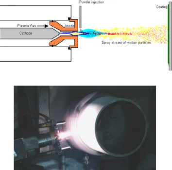
Plasma spraying relies on the thermal energy of a high-temperature plasma jet
generated by running a direct electrical current between a cathode and an annular anode
nozzle [1-3]. The plasma jet typically exits the nozzle with temperatures ranging between
5000 °C and 20000 °C, depending on the gas mixtures and power settings used [2]. The
feedstock particles are then melted, outside the nozzle and in the plasma jet, and
projected at velocities ranging from 80 m/s to 300 m/s onto the substrate where they
rapidly solidify and form a coating. This solidification process occurs so rapidly that it
frequently leads to amorphous microstructures.
A schematic of the plasma spraying process, as well as a plasma spray torch
during a spray process, is shown in Figure 1. Due to the very high temperatures achieved
in the process, a wide range of feedstock materials can be used in this process, ranging
from low to high melting temperature metals to ceramics [4, 5]. In recent years work on
improving equipment from a performance [6] and control [7] stand-point continues.
Although the high temperature achieved in the process allows for a wide range of spray
materials, it has many detrimental effects. The substrate undergoes severe heating, has
unfavorable residual stresses, and the feedstock material undergoes phase transformation
3 Figure 1: Schematic of the plasma spray process (top) and a plasma spray torch
(bottom) during a spray process - courtesy of Gordon England [8].
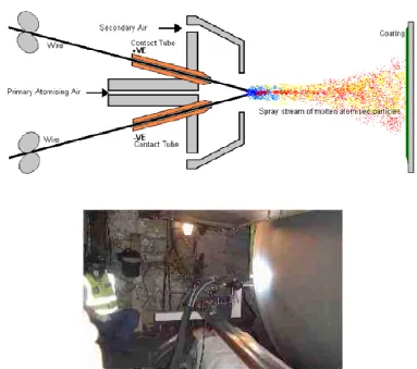
In the wire arc spraying process (also referred to as twin-wire arc spray) a pair of
electrically conductive wires are melted by an electric arc [9, 10]. The molten material is
then atomised by compressed air and propelled towards the substrate surface [11, 12].
The molten particles impacting on the substrate rapidly solidify to form a coating.
A schematic of the wire arc spraying process, as well as a working device, are
shown in Figure 2. The equipment used in this process is rather simple in
construction [8], as the feedstock is in the form of wire and powder handling provisions
4 need for an additional heat source. This has found technology applications in various
fields, from metallic membranes [13] to internal combustion engines [14]. The major
limitation of the process is that its feedstock can only be selected from electrically
conductive materials [8].
Figure 2: Schematic of the arc spray process (top) and an arc spray device (bottom) during a spray process - courtesy of Gordon England [8].
High Velocity Oxygen-Fuel (HVOF) [15] and High Velocity Air-Fuel
(HVAF) [16] technologies are two variations of the combustion thermal spray
process [1]. A schematic of a typical combustion spray device, and a HVOF device
5 reaction between a fuel and oxygen or air as a source of thermal energy for coating
deposition. Typically, kerosene, acetylene, propylene or hydrogen can be used for
fuel [8]. The resulting flame is then fed into a converging-diverging nozzle where the
gases are accelerated at supersonic velocities, leading to jet temperatures of
approximately 3000 °C and velocity range from 1525 m/s to 1825 m/s. Upon exposure to
the high temperature and high velocity flame, the feedstock particles experience a
significant increase in thermal and kinetic energy, resulting in partially melted and/or
softened high-velocity particles. Coating formation is therefore attributed to the
combined effect of splat formation and plastic deformation of the particles upon impact
with the substrate [17].
6 The main advantage of combustion spray processes lies in the very high content
of energy available to the process. A combination of combustion gases at a very high
temperature and a high-speed gas flow can allow successful deposition of many hard [18]
and high-melting-point [19] metals. In addition, coatings of many cermets and ceramics
are also possible using this technology [20, 21].
Another kind of thermal spray process exists, called the detonation spray process,
which relies on an interrupted gas flow. In this process a precisely measured quantity of a
combustion mixture is fed into a straight barrel along with a pulse of powder. The
explosive mixture is ignited using a spark plug. The resulting detonation wave travels
down the barrel while accelerating and heating the powder. The powder particle exits at a
velocity as high as 700 m/s and at a temperature near or above its melting point [22]. The
coatings generated by the process are shown to demonstrate excellent density, bond
characteristics and wear properties [23].
These thermal spray techniques offer many possibilities for creating coatings of a
wide range of materials. However, they also have limitations and disadvantages [1].
These stem from the very high temperatures involved with these processes. These high
temperatures have many detrimental effects on the feedstock material, the substrate, and
the final coating products. These include oxidation or other chemical reactions, possible
melting of the substrate, changes in the microstructure of the feedstock in flight or the
7 Cold spray (also referred to as Cold Gas Dynamic Spraying - CGDS) is a
subcategory of thermal spray processes that offers an alternative to other thermal
spraying processes by operating at significantly lower temperatures. In this process
kinetic energy is used to manufacture coatings: solid powder particles are accelerated at
high velocities (typically 300 m/s to 1200 m/s) in a supersonic inert gas flow in order to
be projected onto the substrate [24].
A schematic of the cold spray process is shown in Figure 4. The supersonic gas
flow is generated by passing the main carrier gas through a converging-diverging nozzle.
The carrying gas is usually heated prior to being introduced to the nozzle, however this
heating action is usually far less than that required to melt the powder particles. Although
cold spraying relies mainly on kinetic energy for the bonding to occur, some heating is
often required in order to enable this bonding.
Figure 4: A schematic diagram of the cold spray process - courtesy of Gordon England [8].
The main distinction between commercial cold spray systems lies in the location
8 upstream of the nozzle throat. Due to the pressure ranges at which they commonly
operate, downstream and upstream injection types are commonly referred to as
low-pressure [25, 26] (for downstream injection) and high-low-pressure [27] cold spray systems,
respectively.
Although this distinction has some impact on equipment design and
manufacturing as well as their capabilities, all cold spray equipment remain principally
the same. The gas dynamic principles of both processes are the same, and the adhesion
and bonding mechanisms are also the same. Heating temperatures are generally far less
than the melting point of the feedstock material, however it is found that localized
melting, due to transformation of kinetic to thermal energy, is possible in some interface
areas between the deformed particles and the substrate [28]. Bonding is shown to be
associated with adiabatic shear instabilities that occur primarily in the perimeter of the
impact zone [29].
Due to tight control over the process temperature in cold spray, negative
implications of excessive heat present in other thermal spray processes can be largely
avoided. Bonding is mostly a result of kinetic energy rather than thermal energy. While it
is shown there is a gas-dynamic limit to how far this kinetic energy can increase [30], it is
widely understood that this increase in energy comes at the cost of thermal energy
reduction [31]. In steady-state transonic flow, under ideal assumptions, total energy of the
gas is principally conserved as gas travels along the device, and any increase in the
9 consequence of using a steady-state flow regime in a spraying device. In a transient flow
regime, such as that of a shock tube [32-35], however, it is possible to have a region in
the flow where increased speed and temperature can co-exist [36, 37]. The Shock-wave Induced Spray Process was developed as a spray process based on this shock tube flow
characteristic [38, 39].
The only other thermal spray process that relies on an interrupted gas flow is the
detonation spray process. In this process, a precisely measured quantity of a combustion
mixture is fed into a straight barrel along with a pulse of powder. The explosive mixture
is ignited using a spark plug. The resulting detonation wave travels down the barrel while
accelerating and heating the powder. The powder particle exits at a velocity as high as
700 m/s and at a temperature near or above its melting point [22]. The coatings generated
by the process are often compared with plasma-sprayed coatings and are shown to
demonstrate excellent density, bond characteristics, and wear properties [23].
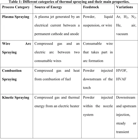
10 Table 1: Different categories of thermal spraying and their main properties. Process Category Source of Energy Feedstock Variations
Plasma Spraying A plasma jet generated by an
electrical current between a
permanent cathode and anode
Powder, liquid
suspension, or wire
Ar, H2, N2,
He, air,
vacuum
Wire Arc
Spraying
Compressed gas and an
electric arc between two
consumable wires
Consumable wire
that takes part in
arc formation
Combustion
Spraying
Compressed gas and heat
from combustion of fuel
Powder injected
downstream of the
torch
HVOF,
HVAF
Kinetic Spraying Compressed gas and thermal
energy from an electric heater
Powder injected
within the nozzle
system
Downstream
and upstream
injection,
steady or
transient
1.2 Shock-wave Induced Spray Process
The Shock-wave Induced Spray Process (SISP) is a method of applying coatings
onto a wide range of substrates [38-40]. It utilizes the kinetic and thermal energy induced
11 variant of CGDS material deposition technique and utilizes a train of gas pulses in an
unsteady interrupted flow.
The SISP process, illustrated in Figure 5, uses moving shock-waves at its core.
Each shock-wave is created by the fast opening and closing of a valve; up to 30 Hz
frequency is presently realisable. When the valve is rapidly opened, and subsequently
closed shortly after, a shock-wave is generated that propagates into the spraying gun,
accelerating and heating the powder present in the gun. Similar to the CGDS process, the
particles then impact on the substrate and deform plastically to produce a coating [29].
SISP, however, differs from CGDS in that it is possible to achieve higher particle impact
temperature due to the unsteady nature of the process.
Figure 5: Schematic of the Shock-wave Induced Spraying Process Device
During each cycle, or pulse, a controlled feedstock powder quantity is placed into
the tube. Correct timing of this action is of paramount importance to the process
performance in that the powder must be present prior to the passage of the shock-wave.
12 1.3 Bonding Mechanism in Kinetic Spraying
In kinetic spraying, bonding occurs when the impact velocity of a particle exceeds
a threshold velocity, commonly referred to as Critical Velocity, Vcr. This critical velocity
depends on several factors, including the spray material and size, impact temperature, and
surface and grain properties of particles and substrate surface.
Upon impact, the particle and the substrate both start to deform at the impact
interface. Beyond critical velocity, this deformation results in such high strain rates that
adiabatic shear instabilities occur, and in this region bonding occurs. This region is a
peripheral slit around the impact circle when impact velocity is just above critical
velocity, and it grows to the center of the impact circle as impact velocity further
increases [29]. Although melting temperatures may be reached locally at the impact
interface, melting is not regarded as the cause for bonding.
Bonding mechanisms for specific particle/substrate combinations have been
examined by a number of researchers. Goldbaum et al [41] studied deposition of titanium
particles on a titanium substrate. They conducted a ‘splat’ test, where the spray device is
moved over the substrate at a fast enough speed to achieve single particle splats.
Microstructural examination of the cross-section of these splats confirm the deformation
of both the particles and the substrate. It was observed that bonding is more pronounced
13 Nakano et al [42] used an aluminum-nitride (AlN) substrate coated with a 100-nm
layer of sputtered titanium and a 100-nm layer of sputtered copper. Copper particles of
5 micron size were then cold sprayed onto this substrate. An observation of the
cross-section of the coated substrate confirms deformation of the particles as well as the
deposited substrate. A wavy boundary was observed between the sputtered titanium and
the sputtered copper, due to shear instabilities. No oxidation layer was observed between
the cold-sprayed copper particles. This indicates that the plastic deformation of the
copper particles lead to formation of a new surface on the boundary of the particles.
Irissou et al. [43] investigated the bonding behavior of pure aluminum, and blends
of pure aluminum and aluminum-oxide (Al2O3) particles. A small and a large particle size
distribution of aluminum, with mean particle diameters of 36.2 microns and 81.5 microns
respectively, were considered. The aluminum oxide has a mean diameter of 25.5 microns.
The large aluminum particles are sprayed under conditions that result in low particle
deformation levels and high porosity levels. It is then observed that under the same
spraying conditions, adding only 7% weight of aluminum oxide to the powder will result
in a high level of deformation of the aluminum particles, and a significantly improved
coating density. This observation suggests that coating properties can be improved by
modifying the powder blend composition and using hard particle additives that can act as
a catalyst in the bonding process.
Plastic deformation, shear instabilities and mechanical interlocking are found to
14 found that no melting occurs at the bonding interface [28]. However, for the case of zinc
coatings, it is found that spraying conditions can lead to local melting at the bonding
interface. When this occurs, bonding is significantly enhanced due to the formation of a
15
Chapter 2.
Literature Review and Objectives
The aim of this chapter is to first introduce the current state of the technology by
summarizing the available literature. The present knowledge of the working principles of
the process is presented. The objectives of the current work are then introduced. The
literature pertaining to the background of technology, and its relation to other similar and
competing technologies, is presented in Chapter 1.
2.1 Previous Studies
The SISP process was developed at the University of Ottawa Cold Spray
Laboratory in 2005. Applications for a patent were filed shortly thereafter [38]. The first
comprehensive description of this process was published in 2007 [39]. It involves
analysis of the process through the use of a one-dimensional model based on shock tube
theory. Experimental examination of the process was conducted using pressure data
obtained from a high-frequency pressure transducer. Selected examples of coatings
produced with the system are presented, illustrating the potential of the process to deposit
various materials. It is shown that this process allows the feedstock particles to be
accelerated to high impact velocities and intermediate temperatures (below melting
temperature). This leads to a lower required critical velocity compared to traditional cold
spraying.
In another study, an analysis of productivity and cost associated with the new
16 processes in regard to commercial feasibility. It is explained that this technology presents
more efficient management of thermal energy. As a result, high levels of performance
can be achieved at lower capital and operational costs than possible with the
high-pressure variation of CGDS. It is concluded that the process is most suitable for OEM
production applications in which high productivity and low operating costs are
paramount. This is in contrast with niche high-value technologies where operation costs
are not of great significance.
A number of studies have also focused on various applications of the process.
Some of these applications include WC-based coatings [44, 45], metallic coating of
aerospace carbon/epoxy composites [46], SiC particulate reinforced Al-12Si alloy
composite coatings [47], as well as various traditional materials sprayed by CGDS (Cu,
Zn, Al) and new ones (amorphous Fe-based) [39]. The technology is presently
commercialized to a beta-stage by the SST Division of CenterLine (Windsor)
Limited [48] under the name WaveRider™ [49]. A picture of a beta-version unit of the
17 Figure 6: Beta version of the first SISP device, named Waverider™. Picture
courtesy of SST, a division of CenterLine (Windsor) Limited [48].
From an analytical standpoint, prior to the current dissertation the main source of
knowledge available to explain the governing physics of the process was a
one-dimensional model [39]. This approach is based on well-established compressible flow
and shock-wave theory. Although the model is able to provide fundamental
understanding of the process, many details of the flow features remain unresolved. This is
due to many limitations of the model. For example, the model divides the flow field into
a few sub-fields, called zones, and predicts a single value for flow properties for the
entirety of each of these zones. This poses a limitation on spatial resolution considering
there are only four of these zones in the solution scheme. Additionally, effects of
turbulence and wall friction are ignored. Both of these effects are expected to be
important considering the high flow speed as well as the very small size of the flow
18 The fundamental flow physics of SISP is closest in nature to that of detonation
spraying process. The physics of the detonation spray process involves a greater level of
complexity due to presence of combustion and chemical reaction. Therefore prior
attempts at modeling of the detonation spray process can serve as a source of knowledge
for the modeling of SISP.
A one-dimensional model of the detonation spray process is presented by
Kadyrov [50]. This model describes the governing equations of gas and particle flows in
a general one-dimensional transient domain. The model accounts for frictional effects as
well as cooling of gas along the tube. However, radial variations of gas properties are
neglected. Due to the inclusion of friction and viscosity, the equations do not have an
analytical solution and therefore are solved numerically. These effects present an
incremental improvement over a more basic one-dimensional analysis presented earlier,
however still falls short of a two-dimensional CFD solution. The model, if applied to
SISP, cannot account for the opening and closing of a valve. It does not model boundary
layer effects, nor is it capable of representing the tapered tip of the SISP spray device.
Another study is reported where a two-dimensional analysis of the gas flow is
considered [51]. Particle behavior in the gas flow is also modeled. However, in this work
gas flow is considered inviscid. A high-resolution shock capturing numerical method, in
conjunction with a Runge-Kutta scheme, are used for solving the system of partial
differential equations. This work adds the second spatial dimension to the problem,
19 presenting the physics of gas flow and concentrates mainly of the properties of particle
behavior. A more enhanced version of this model has also been reported [52], that
presents model validation and some explanation of flow physics. However, viscous and
turbulence effects are still lacking.
2.2 Overview of Flow Physics
SISP relies on consecutive travelling shock-waves, rather than a steady gas flow,
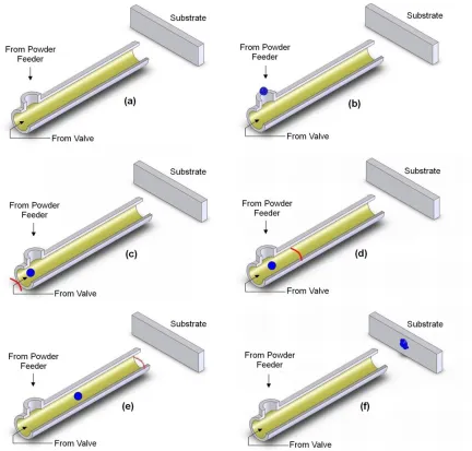
to carry the powder particles towards a substrate. A simplified sequence of images, to
visualize the process progression, is shown in Figure 7. A metered batch of powder
particles is placed in the spray barrel, which is subsequently carried by the flow induced
by the passage of a travelling shock-wave towards a substrate. The batch of powder is
shown in Figure 7 (a) and Figure 7 (b) to come from the powder feeder and enter in the
device. In Figure 7 (c) and Figure 7 (d), the red line represents the shock-wave passing
through the device. The shock-wave picks up, accelerates and directs the powder batch to
20 Figure 7: Consecutive images depicting the intended working principle in the
Shock-wave Induced Spraying Process.
The travelling shock-wave is a result of the coalescence of compression waves
downstream of the valve due to a large pressure difference between the pressure reservoir
and the spray tube [53] (Figure 8 b). The valve closes shortly after this shock-wave is
formed. The passage of this shock-wave creates a zone of high speed and intermediate
temperature in the gas. This induced flow accelerates and heats the powder feedstock
21 similar to the cold spray process. The cycle is repeated after the complete passage of a
shock-wave when the pressure inside the gun drops and reaches the ambient atmospheric
pressure.
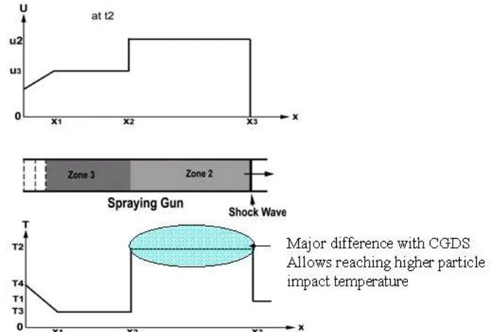
Figure 8: Schematic of the SISP spray device through one pulse spray cycle. Reproduced with permission [39].
The different zones in the flow can be mathematically represented using the
one-dimensional transient model of the flow that was previously mentioned in Section 2.1.
The one-dimensional model predicts the four distinct zones in the physical space,
22 different flow variables in zones one through three, and predicts how these zones evolve
in time.
Figure 9: Schematic of the one-dimensional model.
The problem considered in the one-dimensional model is concerned with
estimating the flow properties in zone 2 based on those in zones 1 and 4. Zone 1
represents the tube when empty from the flow of the preceding pulse, and zone 4 is the
high-pressure region in the valve prior to its opening. The value of pressure in zone 2,
based on the known conditions in zones 1 and 4, can be obtained using [39, 53]:
(1)
where c is the speed of sound and γ is the specific heat ratio. Values of temperature,
density and the induced gas velocity in zone 2 can then be found using [39, 53]:
(2)
23
(4)
Solving these equations indicates that zone 2 will possess an elevated temperature
and increased velocity concurrently. The promise of the technology mainly lies in this
fact. Theoretical instantaneous values of gas speed and temperature just prior to the
departure of the shock-wave from the spray tube are shown in Figure 10. This is the
unique feature of SISP due to the unsteady nature of the flow. In steady-state cold spray
processes increased gas velocity is always accompanied by a drop in gas temperature.
Figure 10: Theoretical instantaneous values of gas speed and temperature just prior to the departure of the shock-wave from the spray device. Reproduced with
24 2.3 Objectives
This dissertation aims to advance the knowledge of the working principles of the
Shock-wave Induced Spraying Process (SISP) through a systematic approach and use of
advanced modeling tools. The specific objectives of this work are listed below:
1. To create a Computational Fluid Dynamics (CFD) model of a generic version
of the spray device. This includes a reservoir, a valve, a tube, a representative substrate as
well as a portion of the adjacent surroundings. Using this model it is desired to study
various flow properties during the travel of a single shock-wave, in order to explain the
underlying physics of the spray process. The model is to be general in nature, allowing
investigation of the effect of various parameters on the resulting flow. This will include
an accurate model of the in-line heater and a realistic model of the valve. This model will
be validated through measurement and comparison of flow pressure and temperature
where possible.
2. To use the model to examine effects of the important fundamental parameters
on the flow properties of the device. These parameters will include the temperature and
pressure of supply gas as well as the type of the carrier gas.
3. To model the behavior of particles traveling in the flow field. The goal is to
examine the kinetic and thermal energies of the particles upon their impact on the
25 4. To use this enhanced model to investigate the effect that particle injection
location and timing has on the particle impact velocity and temperature.
5. To derive an estimation of the particle critical velocity [54] using available
correlations [29] and make a comparison of particle velocity upon impact with
corresponding critical velocity to determine the ability of obtaining a coating under a
specific set of conditions.
6. To examine the influence of various operating parameters on the final outcome
of the coating process using this model. These parameters include the spray frequency,
main heater and powder heater set-point, particle material and size, length of the main gas
heater as well as powder loading ratio.
2.4 Contents of Dissertation
The dissertation consists of five chapters. Chapter 1 introduced the working
principles of thermal spray processes, and how SISP fits into this picture. In Chapter 2, a
survey of the current state of the art of the SISP process was presented, and the general
physics of the flow was described. The objectives of this undertaking were laid out in this
chapter in light of where the technology currently stands. The remainder of the
dissertation gives the details of how these are achieved.
Chapter 3 focuses on the details of the modeling technique, flow equations and
26 simulation work is laid out, and various stages of the work are explained. Methods used
to validate the numerical model are also presented. Chapter 5 presents the results of the
gas flow and the particle flow separately. The effects that many parameters have on the
potential outcome of the spray process are investigated. Finally, the conclusions are
drawn in the final chapter
27
Chapter 3.
Numerical Methodology
Several details of the gas dynamics model, including the geometry and
assumptions, governing equations, grid considerations as well as boundary and initial
conditions are described in this chapter. The particle flow simulation is then described, in
which the Discrete Phase Model is used.
3.1 Computational Gas Dynamic Model
The modeling presented in this study is conducted in three distinct stages, to
incrementally increase the model complexity level while ensuring some level of
validation at each stage. First, a simplified model is developed in Stage One focusing on
the basic flow features resulting from the fast opening and closing of a valve. Due to the
fundamental nature of this stage of the study and emphasis on understanding the flow
physics, the geometry used at this stage is not an exact representation of the actual spray
device.
Once the flow physics have been modeled, properly validated, and fully
explained, the model is expanded to more closely represent the working device in Stage
Two. A representative geometry is used at this stage and important process features such
as gas heating and valve behavior are modeled. In Stage Three of the study, particle flow
is also included and analyzed. A more completely representative model of the process is
28 3.1.1 Problem Statement
The main elements of the system, shown schematically in Figure 11, include a
high-pressure gas reservoir and a valve connected through a gas line, a spray tube, and a
flat substrate. Different stages of the study use different values for the device length and
therefore only the other geometrical parameter values are shown in this figure.
Figure 11: A generic schematic of the flow region.
The spray tube considered in this study is a standard ¼” tubing (6.35 mm OD)
with 0.035” (0.89 mm) wall thickness, resulting in a spray tube internal diameter of
approximately 4.6 mm. The tube total length varies in different stages of the study. The
tube has a tapered end which is 105 mm in length that leads to the end which has an
internal diameter of 6.3 mm and is open to ambient air. The purpose of this tube taper is
two-fold; it increases the spray pattern footprint while it increases the gas speed.
3.1.2 Assumptions
The main component, or heart, of the SISP system is its valve. A picture as well
29 are generated using ICEM CFD (ANSYS, Canonsburg, Pennsylvania, USA) after
extracting fluid volumes from the native CAD model. The model was imported to ICEM
CFD using IGS Wireframe format. The native CAD model was generated in Autodesk
Inventor (Autodesk, San Rafael, California, USA) for the purpose of manufacturing. The
channels shown in Figure 12 (b) are formed in a stationary seat shown in Figure 12 (c).
The volume shown in Figure 12 (d) rotates and gas passage is formed as the openings of
this rotating volume align with the openings of the stationary seat. These openings are
extended along the radial direction in order to ensure rapid opening and closing.
The flow is solved in an axisymmetric domain shown in Figure 11. Although the
physical valve is of the rotary type, a ball-seat type valve is found to be a good
representation as long as the model appropriately represents the kinematics of the real
valve. The surface area of the model when fully open is initially equated to that of the
real valve opening, leading to a stroke value of 0.6 mm. When the flow is modeled using
this value for stroke, it is shown (in Section 4.2.2) that pressure peaks predicted by the
model are lower than those measured by pressure transducers along the device tube, by
approximately 20%. It is speculated that this is due to a difference in the discharge
coefficient between the real and the modeled valve. Although the two valves have equal
cross-sections when fully open, the modeled valve is more resistive to flow due to
boundary layer formation along a very long surface compared to the real valve. The
stroke was therefore increased by 20%, to approximately 0.72 mm. With this change the
30 behavior varies among the various stages of the study that will be explained in the next
chapter.
Figure 12: Picture and a CAD representation of the rotary-style valve used in the SISP device
(a)
(b) (c)
31 The pressurized gas source is replaced in the model by a conical-shaped chamber
attached to the valve entrance. The inlet to this chamber has a diameter of 150 mm,
resulting in an area ratio between this section and the spray tube greater than 1000. This
section can accurately represent the flow from a constant-pressure chamber. Based on the
area ratio and using isentropic equations this assumption can be in error by a maximum
of 0.01%.
In the physical device, gas heating is achieved by resistively heating a section of
the spray tube. It is modeled using empirical information from the experiments. In the
experiments an electrical control system ensures that the tube surface temperature at the
end of this heating section reaches the desired input value. In order to model this effect,
the actual temperature distribution along the length of the heating portion of the tube was
measured using K-type thermocouples at certain intervals on the exterior of the heating
tube. As shown in Figure 13, this temperature distribution can be closely approximated
by a linear relation whose initial value is room temperature and final value is the set input
temperature. Simulations were performed using the measured temperature profile and
using the linear approximation. It was found that the linear approximation did not change
the resulting predicted flow field, gas speed as well as gas temperature considerably (that
is less than 5% compared to a case where the measured temperature profile was used).
Consequently, the linear approximation is used as it allows for an easy change of the
![Figure 3: Schematic of the HVOF process (top) and a HVOF device (bottom) during a spray process - courtesy of Gordon England [8]](https://thumb-us.123doks.com/thumbv2/123dok_us/1420026.1174548/33.612.146.503.358.682/figure-schematic-process-device-process-courtesy-gordon-england.webp)
![Figure 6: Beta version of the first SISP device, named Waverider™. Picture courtesy of SST, a division of CenterLine (Windsor) Limited [48]](https://thumb-us.123doks.com/thumbv2/123dok_us/1420026.1174548/45.612.168.483.72.292/figure-waverider-picture-courtesy-division-centerline-windsor-limited.webp)
![Figure 8: Schematic of the SISP spray device through one pulse spray cycle. Reproduced with permission [39]](https://thumb-us.123doks.com/thumbv2/123dok_us/1420026.1174548/49.612.173.476.170.543/figure-schematic-sisp-spray-device-pulse-reproduced-permission.webp)