Face Detection System Based on Feature-Based Chrominance
Colour Information
Y.H. Chan and S.A.R. Abu-Bakar
Dept. of Microelectronics and Computer Engineering
Faculty of Electrical Engineering
Universiti Teknologi Malaysia
81310 Skudai, Johor, Malaysia.
{
[email protected]
and
[email protected]
}
Abstract
This paper presents a novel face detection system based on feature-based chrominance colour information from an image containing one face in indoor environment with non-uniform background. The face detection algorithm is based on the Adapted Chain Code (ACC), eye detection and Modified Golden Ratio (MGR). ACC is proposed to obtain a face boundary. MGR attempts to extract part of a face that includes eyes, eyebrows, nose and mouth, based on the detected eyes’ positions. Experimental results show that the proposed algorithm is able to detect a face of near frontal with high accuracy. The database consists of faces with and without spectacles, wearing headscarf and without wearing headscarf.
1. Introduction
Face detection is an important preprocessing module for an efficient face recognition system. The goal of face detection is to determine whether or not there are any faces in a given arbitrary image and, if present, return the image location and extent of each face [1]. From work reported in [2], face detection is divided into two approaches, namely feature-based approach and image-based approach. In feature-image-based approach, the apparent properties of the face such as skin colour and face geometry are exploited. Other examples of feature-based techniques are motion analysis and snakes. Image-based approach addresses face detection as a general recognition problem, classifying examples into face and non-face prototype classes.
Among the face detection approaches, colour and motion analysis are among the most popular among researchers. As stated in [3] and [4], motion and colour analysis are suitable algorithms for face detection. Some
examples of colour analysis are [4, 5 and 6]. The work done by [3] incorporates both colour and motion analysis in locating heads and faces. Motion analysis can only be applied to dynamic image sequences, wheareas colour analysis can be performed on both static images and dynamic image sequences.
The proposed algorithm is focused on colour analysis in skin colour segmentation and eyes candidate estimation. ACC estimates the boundary of a face region to allow further eye candidates estimation to ensure that there is a pair of eyes in the boundary. The face boundary is refined based on the detected eyes’ positions. The face is detected by extracting the important face features, including eyes, eyebrows, nose and mouth based on the positions of detected eyes and the refined boundary.
This paper is organized as follows: Section 2 presents the proposed eye locating algorithm. Section 3 illustrates the proposed face detection algorithm based on detected eyes in Section 2. The proposed ACC is explained in Section 4. Section 5 shows the performance of the proposed algorithm and finally conclusions are drawn in Section 6.
2. Eye locating
estimated images. If no valid eye position is obtained, then it can be concluded that the input image does not contain a face. If eye positions are approximated, eye detection will be performed. The eye locating algorithm is given inFigure 1.
Figure 1. Eye locating flow diagram
2.1. Skin colour segmentation
According to [7], the apparent difference in skin colour that viewers perceived is mainly due to the darkness or fairness of the skin, characterized by the difference in the brightness of the colour, which is governed by Y but not Cb and Cr in YCbCr colour space.
Y is luminance component which corresponds to brightness component, whereas Cb and Cr are chrominance components which correspond to colour components.
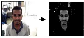
The ranges for Cb and Cr are determined empirically from 16 randomly selected skin region. The range of Cb is between 95 and 126 while the range of Cr is between 140 and 168. The ranges are used for quick segmentation.Figure 2 shows an example of an original image and a skin segmented image.
Figure 2 Original face image and skin colour segmented image
2.2. Face boundary estimation
Face boundary estimation is aimed at estimating the possible range for eyes in Y-axis. Once the image is skin segmented, it is then wavelet transformed. This is done to
segmented, it is then wavelet transformed. This is done to reduce the noise inside skin colour segmented area as well as to reduce the processing time by reducing the size. In our case, we make use the Haar wavelet transform. Next, the segmented image is binarized before morphological opening operation is applied. The resulting image is called the opened binary image. The opened binary image is the input image for face region’s boundary estimation using ACC algorithm. An example of image containing face boundary is illustrated in Figure 3.
Figure 3 Image containing face boundary
2.3. Eye candidates estimation
Inspired by the work reported in [4], eyes’ candidate segmentation is done by applying the following equation to reduce the computation complexity of eye map used by Hsu et al. [4]:
255
)
,
(
)
,
(
)
,
(
u
j
i
Cr
j
i
Cb
j
i
Eye
c (1)where
i
is column,i
=0, 1, 2, …255j
is row,j
=0, 1, 2, …255)
,
(
i
j
Cb
is the pixel value of Cb component at location(
i
,
j
)
)
,
(
i
j
Cr
is the pixel value of Cr component at location(
i
,
j
)
)
,
(
i
j
Eye
c(
is the pixel value of the segmented image
at location
i
,
j
)
In the first stage, the wavelet transform is performed on the eyes’ candidate segmented image. Multilevel thresholding with 3-level priority is introduced for non-zero pixels after obtaining the wavelet transformed image . Thresholds are determined experimentally. Each pixel in the image is assigned to one of the four categories as the following:
G1: Eyerc(i,j) 255 if Eyerc(i,j)!230 (2)
G2:Eyerc(i,j) 128if 223Eyerc(i,j)d230 (3)
G3:
Eye
rc(
i
,
j
)
64
if 215Eyerc(i,j)d223 (4) G4: Eyerc(i, j) 0 if Eyerc(i,j)d215 (5)where
i
is column,i
=0, 1, 2, …127j
is row,j
=0, 1, 2, …127)
,
(
i
j
Eye
rc is the pixel value of the wavelettransformed segmented image at location
(
i
,
j
)
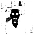
3-level priority is proposed in order to tackle the problem of misclassifying noise as eyes during eye positions approximation. A pixel that is likely to be part of an eye will have higher priority. 3-level priority is used when comparing multilevel thresholded image with eroded binary image. An example of multilevel thresholded image of dimension 128x128 pixels is demonstrated inFigure 4.
Figure 4 Multilevel thresholded image
Comparison is done between the wavelet transformed possible eyes’ candidate segmented image and face boundary image to obtain a masked eye region image that includes every pixel which is within the boundary.
)
,
(
i
j
Eye
rcIn locating the position of the eye, the masked eye region image with the highest priority in G1 is set to a value of 255 (white pixel) while pixels of other priorities in G2, G3 and G4 are set to a value of 0 (black pixel). If suppose the highest priority fails to approximate eye positions, then pixels in G1 and G2 of the masked eye region image are set to a value of 255 (white pixel) while setting pixels of other categories to a value of 0 (black pixel). If both the highest and medium priority fail to approximate eye positions, pixels in G1, G2 and G3 of the masked eye region image are set to a value of 255 (white pixel) while setting pixels of G4 to a value of 0 (black pixel). From this operation, a binary masked eye region image is obtained. In order to enlarge the area of the eyes, closing operation is performed onto the binarytumasked eye region image. A 3x3 structuring element is used to perform dilation, whereas 3x1 and 1x3 structuring elements are used during erosion to fill
gaps within detected eyes’ pixels resulting in an estimated eye candidates image.
2.4. Eye positions approximation
The eye position candidate is obtained by simply dilating the detected skin boundary twice using a 3x3 structuring element and comparing it to the estimated eye candidates image to obtain the eye region within the detected skin boundary. This is to eliminate unnecessary noise at the boundary of skin colour region.
The image that contains possible eye candidate region is scanned to obtain approximate position of eyes by using a condition that distance between the first detected eye and the second detected eye is at least 14 pixels. This distance was determined empirically based on the foot distance between the camera and the person is set to 35cm.
3-level priority of multilevel thresholding plays its role in determining approximate eye positions. The highest priority threshold is taken into consideration while performing eye positions approximation. If this fails, the second priority threshold will be used and if this also fails, the lowest priority threshold is used before the eye position is located. The last resort to obtain approximate eye positions if all of the above fail is to use vertical projection histogram to find approximate eye positions.
2.5. Eye detection
The masked eye region image obtained from Section 2.3 is compared to the dilated-twice face boundary to obtain a refined eye candidate region to eliminate unnecessary noise at the boundary of skin colour region. The refined eye candidate region is scanned to obtain detected eyes’ position by applying the same condition as the condition applied during eye positions approximation. If this fails, eyes will be detected from the possible eye candidate image. If all of the above attempts fail, face boundary will be estimated once again based on the binary image, not the opened binary image. The detected left eye is positioned at
(
and detected right eye is positioned at .Figure 5 shows an example image of dimension 128x128 pixels containing detected eyes.)
,
y
EyeL
Figure 5 Image containing detected eyes
3. Face detection
Figure 7 Modified Golden Ratio Face detection is aimed at detecting only the face
region to ensure that a face is located in the particular image. Face detection flow diagram is illustrated in
Figure 6.
2
EyeR
EyeL
x
(7)1
se
x
x
W
(8)W
W
H
1
.
618
0
.
27
6
1
6
1
|
u
(9)W
W
H
1
.
618
0
.
73
9
4
9
4
|
u
(10)Figure 6 Face detection flow diagram
where
H
is the height of the face3.1. Face boundary refinement
W
is the width of the faceEyeL
is the x-coordinate for left eye The face boundary image is refined by using the ACCalgorithm based on the detected eyes’ positions from Section 2.3. The refined face boundary is crucial to determine the width of the face for higher efficiency of face detection.
EyeR
is the x-coordinate for right eyex
is the x-coordinate for the center point between left and right eyess
x
is the left intersection x-coordinate between face boundary and the reference axis3.2. Face extraction
e
x
is the right intersection x-coordinate between face boundary and the reference axisThe Y component from the input image is first wavelet transformed. A face then will be extracted from this transformed Y component by using modified golden ratio.
The ratio for an ideal face is approximated to a value of 1.618. The center point
(
between detected lefteye, and right eye, is an
important point to obtain the width,
W
and height,)
,
y
x
)
,
(
EyeL
y
(
EyeR
,
y
)
H
of a face that contains important face features. The straight line connecting
EyeL
,x
and is the reference axis when determining the distance between eyes and part of the forehead, and distance between eyes and part of the chin. The width of the face,W
is obtained by calculating the distance between two intersection points, and between the face boundary and the reference axis. The distance between the reference axis and part of the forehead is empiricallydetermined to
EyeR
s
x
x
eH
6
1
, which is approximated to
0
.
27
W
. According to Frakas and Munro [8], golden ratio foran ideal face is given by:
618
.
1
2
5
1
|
{
width
height
(6)
From empirical experiments, the distance between reference axis and part of the chin is determined to be
H
9
4
, which is rounded up to . The resulting
region will be a squared of size
W
xW
. The empirical experiments were carried out by experimenting twenty face images randomly selected from face database.W
73
.
0
)
,
(
x
y
(a) exception LACC (b) exception RACC
Figure 9 Exception LACC and RACC
4. Adapted chain code
FromFigure 9, ‘x’ is the origin. For exception LACC, p3a has the highest priority, followed by p3b, p3c, p3d, p3e, p4a, p4b, p4c, p4d, p4e, p4f, p4g and p4h in an anticlockwise manner. Similar case also applies to RACC except that the scanning is done in a clockwise manner.The aim of the ACC algorithm is to obtain a face boundary from an image containing possible face region. The quality of the tracked boundary depends on the quality of the input image which contains possible face
region corrupted by noise. The operation of ACC is that when a starting point is obtained, RACC is performed. The stopping condition for RACC is when all directions of RACC fail to find a valid pixel. Once RACC is stopped LACC is started until the same stopping condition is met. The two ending points are connected by connecting LACC’s x-coordinate ending to RACC’s x-x-coordinate ending. The same procedure will be done for connecting LACC’s y-coordinate ending to RACC’s y-y-coordinate ending. For a good quality tracked boundary, both ending points of LACC and RACC should be the same point.
The proposed ACC consists of two adapted chain codes to obtain the face region’s boundary. To start with, the initial condition needs to be fulfilled in order to determine the starting point of ACC. The initial condition is necessary to ensure that ACC is performed on a considerable region.
Figure 8illustrates the initial condition for ACC, Left ACC (LACC) and Right ACC (RACC).
5. Experimental results
An experiment has been carried out using 80 face images from the face database consisting of near frontal faces of different sizes from individuals of different height ranging from 150cm to 179cm (we use our own Asian faces). Images contain non-uniform background in indoor environment with some similar skin colour region. The composition of database individuals are: 1) 20% of the individuals with spectacles, 2) 6.25% are individuals with headscarf (tudung), 3) 6.35% individuals with spectacles and tudung, 4) 67.5% individuals without spectacles and withouttudung. From the 80 tests carried out, the face detection accuracy is 91.25% due to three degrading factors. Both glasses and
tudung tend to degrade the performance of the proposed face detection algorithm because eyes are “blurred” by a pair of glasses and tudung tends to partially occlude the face. Besides, large skin colour background will result in misdetected face region boundary, thus preventing eyes to be detected precisely. This will result in inaccuracy when detecting a face. Faces of different sizes with different height from different races can be precisely detected if both eyes’ positions and refined face boundary are of good quality. algorithm in Figure 10.
(b) Left Adapted Chain Code
(c) Right Adapted Chain Code (a) Initial condition
Figure 8 Initial condition, Left Adapted Chain Code and Right Adapted Chain Code
Consider a pixel at location , ‘x’ is the origin. For the initial condition, all pixels at location i1, i2, … i29 and i30 must have pixel value of 255. If this initial condition is met, is the starting point of RACC and LACC. For LACC, p1a has the highest priority, followed by p1b, p1c, p1d, p1e, p2a, p2b, p2c or c1, p2d or c2, p2e or c3, p3a, p3b, p3c, p3d, p3e, p4a, p4b, p4c, p4d and p4e in an anticlockwise manner, whereas for RACC, the arrangement of priority is the same as LACC except that the scanning will be in a clockwise manner. There is one exception case for the above LACC and RACC, which is after determining eyes’ positions. Figure 9 shows the exception LACC and RACC.
7. References
[1] Ming-Hsuan Yang, D. J. Kriegman, and N. Ahuja, “Detecting Faces in Images: A Survey,”IEEE Transactions on Pattern Analysis and Machine Intelligence, vol. 24, pp. 34-58, 2002.
[2] E. Hjelmas, and Boon Kee Low, “Face Detection: A Survey,”Computer Vision and Image Understanding, vol. 83, pp. 236-274, 2001.
[3] Graf, H. P., Cosatto, E., Gibbon, D., Kocheisen, M. and E. Petajan, “Multi-Modal System for Locating Heads and Faces,”
Proceedings of 2nd International Conference on Automatic Face and Gesture Recognition, Oct. 14-16, 1996.
[4] Rein-Lien Hsu, Mohamed Abdel-Mottaleb, and A. K. Jain, “Face Detection in Color Images,” IEEE Transactions on Pattern Analysis and Machine Intelligence, vol. 24, pp. 696-706, 2002.
Figure 10 Some results of the test images
6. Conclusions
[5] C. Garcia, G. Zikos, and G. Tziritas, “Face Detection in Color Images using Wavelet Packet Analysis,” IEEE International Conference on Multimedia Computing and Systems, vol. 1, pp. 703-708, 1999.
In this paper, a feature-based face detection algorithm based on chrominance colour information is proposed. This face detection scheme is able to detect faces captured from above, which are not exactly frontal faces of different sizes from individual of different height ranging from 150cm to 179 cm of Asian people. Non-uniform background in indoor environment with some similar skin colour region is chosen to ensure the robustness of the algorithm. Wavelet transform is incorporated in the proposed detection scheme to reduce noise during skin colour segmentation, as well as to reduce the size of an image while preserving details from the original image. ACC is proposed to quickly locate a face region’s boundary. The position of a face is further confirmed by eye detection algorithm. Only important features of a face are extracted by applying the MGR, thus serves as a potential preprocessing module for face recognition.
[6] F. Moreno, Juan Andrade-Cetto, and A. Sanfeliu, “Localization of Human Faces Fusing Color Segmentation and Depth from Stereo,” Proceedings of eighth IEEE International Conference on Emerging Technologies and Factory Automation, vol. 2, pp. 527-535, 2001.
[7] Douglas Chai, and Abdesselam Bouzerdoum, “A Bayesian Approach To Skin Color Classification In YCbCr Color Space,”Proceedings of TENCON, vol. 2, pp. 421-424, 2000.