ABSTRACT
SANDUKAS, STEFAN. Development and Analysis of Bioactive CaP Coatings for Biomedical Implants. (Under the direction of Dr. Afsaneh Rabiei.)
Hydroxyapatite (Ca10(PO4)6(OH)2, HA) and other calcium phosphate coatings have been established as being highly effective for enhancing bone-bonding to orthopedic and dental implants. Commercially-produced HA coatings exhibit weak adhesion to substrate surfaces as well as poor mechanical properties, arising from a
non-homogeneous microstructure. This research investigates the development of improved HA coatings on metallic and polymeric substrates by physical vapor deposition
methods.
In the preliminary study, functionally-graded hydroxyapatite coatings doped with silver (FGHA-Ag) on titanium substrates, deposited by ion beam assisted
deposition (IBAD), were studied in terms of microstructure, dissolution behavior and biological response. It was determined that release of Ag from FGHA-Ag coatings was controlled by the functionally graded microstructure, with Ag being released rapidly at first and gradually decreasing. FGHA-Ag1 and FGHA-Ag2 coatings, with 1 and 3 wt% Ag respectively, were found to promote optimal osteoblast attachment and growth,
whereas FGHA-Ag3 coating was determined to exhibit toxicity to osteoblast cells, as a result of high Ag content (6.6 wt%). It was concluded that optimal Ag-doping is
between 1 and 3 wt%, in order to release Ag at a sufficient rate to produce an
The main focus of this research has been on development and optimization of crystalline HA coatings on polymer (polyetheretherketone, PEEK) substrates. As PEEK is a relatively new biomaterial, bioactive-coating of PEEK is not well studied and has yet to be optimized. HA coatings were deposited by RF magnetron sputtering in order to produce thin, well-adhered coatings with uniform, homogenous microstructures. Due to the amorphous nature of sputtered HA films and the temperature sensitivity of PEEK, lower temperature heat treatment methods of HA crystallization were explored, and yttria-stabilized zirconia (YSZ) was used as a thermal barrier coating between the PEEK substrate and the HA coating.
The dual-layer coating of approximately 1.2µm, consisting of a YSZ layer of ~ 450nm and an HA layer of ~ 750nm, initially exhibited an average adhesion strength of 15.1 MPa to the PEEK substrate. Plasma activation of the PEEK substrates before deposition resulted in an increase in coating adhesion strength to 33.4 MPa, which is significantly higher than that of existing HA-coated PEEK materials.
cross-sections revealed that after microwave annealing, the HA coating exhibited a columnar crystalline microstructure, similar to that of the underlying YSZ crystalline layer. It is suggested that the existence of the crystalline YSZ layer aids in the formation of the HA layer upon heating. SEM-EDX showed that the HA coating layer has a Ca:P ratio close to that of stoichiometric HA, before and after crystallization, while FTIR revealed that the HA is hydroxyl-deficient, indicating a need for water vapor exposure, either during or after heat treatment. Finally, culture tests showed a significant increase in initial cell attachment and growth on microwave-annealed coating surfaces, suggesting that this surface is more stable and provides increased surface area for cell attachment
Development and Analysis of Bioactive CaP Coatings for Biomedical Implants
by
Stefan Sandukas
A dissertation submitted to the Graduate Faculty of North Carolina State University
in partial fulfillment of the requirements for the degree of
Doctor of Philosophy
Mechanical Engineering
Raleigh, North Carolina 2012
APPROVED BY:
________________________________________ ________________________________________ Dr. Afsaneh Rabiei Dr. Carl Koch
Chair of Advisory Committee
ii
DEDICATION
iii
BIOGRAPHY
Stefan Sandukas was born in Raleigh, North Carolina in 1981. He received his Bachelor’s and Master’s degrees from the Materials Science and Engineering
Department at North Carolina State University in December 2002 and December 2005, respectively. Starting in August 2006, he joined Dr. Rabiei’s research group, the
iv
ACKNOWLEDGEMENTS
First and foremost, I would like to express my deep gratitude to Dr. Rabiei, my research adviser, for her continued support, advice and patience over the last several years. Without her sincere encouragement and excellent advice, this research would have been impossible. Dr. Rabiei’s dedication to her students is inspirational and has enriched my life as I have had the opportunity to conduct research at national
laboratories both in the US and overseas.
I would like to offer my sincere thanks to my committee members Dr. Koch, Dr. Ngaile, Dr. Saveliev and Dr. Kuznetsov for their valuable time and advice in completing this work.
I am pleased to acknowledge the National Science Foundation for the financial support (Grant No: CMMI - 0600596 and IREE - 0738365 ) and Oak Ridge National Laboratory for access to the research facilities of the Center for Nanophase Materials Sciences (CNMS) and the Shared Research Equipment user facility (SHaRE), (Grant No: CNMS-2005-070 and CNMS-2007-096). Special thanks to Dr. Laura Edwards, Dr. Christopher Rouleau, Dr. Andrew Payzant, Dr. Jason Fowlkes, Dr. Dale Hensley, Dr. Darrell Thomas, and Dr. David Joy for their training and assistance in completing the research at ORNL.
v
I was fortunate to have access to the research facilities of the Nanofabrication Facility (NNF) and Analytical Instrumentation Facility (AIF) at NCSU. Special thanks to Dr. Marcio Cerullo and Mr. Henry Taylor of the NNF, as well as Dr. Roberto Garcia and Mr. Chuck Mooney of the AIF, who were of great help to me for their assistance and training.
Thanks also go to all the members of our research group including former graduate students Dr. Xiao Bai and Dr. Lakshmi Vendra, and current graduate students Mr. Matias Garcia Avila and Ms. Shuo Chen for their friendship, assistance and
suggestions in completing this work. I would like to thank Mr. Rufus Richardson and Mr. Mike Breedlove at machine shop for their assistance in manufacturing tools for our experiments, as well as the MAE staff of the main office for their help in processing the orders and shipping associated with this project.
vi
TABLE OF CONTENTS
LIST OF FIGURES ...ix
LIST OF TABLES ... xiii
LIST OF ABBREVIATIONS...xiv
CHAPTER 1: INTRODUCTION ...1
1.1. Spinal deformities, diseases and instability ...1
1.2. Biomedical implants used in spinal fusion procedures ...2
1.3. Biocompatibility ...7
1.4. Materials used in spinal fusion cages ... 11
1.5. Hydroxyapatite coatings... 14
1.5.1. Functionally Graded Hydroxyapatite (FGHA) Coatings ... 16
1.5.2. Hydroxyapatite coatings doped with antibacterial agents ... 19
1.6. Yttria-stabilized zirconia intermediate layer ... 20
1.7. Deposition of HA/YSZ bilayer coating by RF magnetron sputtering ... 21
1.8. Crystallization of hydroxyapatite coating on PEEK ... 24
1.9. Objectives ... 28
CHAPTER 2: LITERATURE REVIEW ... 30
2.1. PEEK ... 30
2.1.1. Physical and chemical properties of PEEK ... 31
2.1.2. Processing of PEEK ... 37
2.1.3. Mechanical properties of PEEK ... 41
2.1.4. PEEK composites ... 44
2.1.5. Resistance to radiation, elevated temperature, and chemical sterilization ... 48
2.1.6. Imaging Properties... 50
2.1.7. Biocompatibility of PEEK ... 53
2.1.8. PEEK in spinal implants ... 57
2.1.9. Plasma activation of PEEK surfaces ... 60
2.2. Bioactive coatings ... 62
2.2.1. Hydroxyapatite coatings ... 63
2.2.2. Commercially-produced hydroxyapatite coatings ... 66
2.2.3. Experimental methods of applying HA coatings... 69
2.2.4. Bioactive coatings on PEEK substrates ... 75
2.2.5. Yttria-stabilized zirconia in bioactive coatings ... 78
2.2.6. Low temperature crystallization of Hydroxyapatite Coatings ... 86
vii
CHAPTER 3: FUNCTIONALLY-GRADED HYDROXYAPATITE COATINGS WITH AG-DOPING ON
TITANIUM SUBSTRATES... 94
3.1. Introduction ... 94
3.2. Materials and Methods... 95
3.2.1. Preparation of Titanium substrates... 95
3.2.2. Processing of Coatings ... 96
3.3. Analysis of FGHA-Ag coatings ...101
3.3.1. TEM Analysis of coatings ...101
3.3.2. Cell detachment study ...101
3.3.3. Measurement of shear force necessary to detach a cell from surface ...103
3.3.4. Measurement of cell adhesive area ...105
3.3.5. Cell Count ...106
3.3.6. Cell Viability Study ...107
3.3.7. Silver Release Test ...107
3.3.8. Surface Profilometry...109
3.4. Results ...110
3.4.1. TEM of coating and coating/substrate interface ...110
3.4.2. Evaluation of cell affinity to coating surfaces by cell detachment shear force measurement ...113
3.4.3. Cell culture assay ...115
3.4.4. WST-1 Assay ...120
3.4.5. Ag release test ...121
3.4.6. Surface Roughness ...122
3.5. Discussion ...123
3.6. Summary ...126
CHAPTER 4: HYDROXYAPATITE COATINGS ON PEEK SUBSTRATES ...128
4.1. Introduction ...128
4.2. Materials and Methods...129
4.2.1. Preparation of PEEK substrates...129
4.2.2. Plasma activation of PEEK substrates ...132
4.2.3. Conditioning of sputtering targets before use ...134
4.2.4. Radio Frequency Magnetron Sputtering System ...135
4.2.5. Coating Deposition ...136
4.2.6. Post-deposition heat treatment of coatings...140
4.3. Analysis techniques ...142
4.3.1. Determination of deposition rate ...142
4.3.2. Coating adhesion strength ...145
4.3.3. Optical Microscopy...147
4.3.4. X-ray diffraction ...147
4.3.5. Scanning Electron Microscopy ...148
4.3.6. Scanning Electron Microscopy with energy dispersive X-ray (EDX) ...148
viii
4.3.8. Cell Culture Tests...149
4.4. Results ...150
4.4.1. Deposition Rate...150
4.4.2. Physical and Mechanical Properties ...155
4.4.3. Optical Microscopy...158
4.4.3. Microstructural Observation ...167
4.4.5. Compositional Analysis...175
4.4.6. Biological Response ...182
4.5. Discussion ...184
4.6. Summary ...191
CHAPTER 5: CONCLUSIONS ...193
CHAPTER 6: SUGGESTIONS FOR FUTURE RESEARCH ...197
ix
LIST OF FIGURES
Figure 1-1. Spinal fusion cage (PROT Lumbar Cage manufactured by Merries
International Inc.) ... 4
Figure 1-2. Spinal fusion cage inserted between two vertebrae in the lumbar spine .... 5
Figure 1-3. Cross-sectional image of human vertebra ...10
Figure 1-4. Fluorescent images of HEPM cells cultured for 24 h on FGHA coating (right) compared with Ti control (left). Stains: DAPI-Nucleus (Blue), FITC-Actin (Green), TRITC-6,4 Integrin (Orange-Red)...18
Figure 1-5. Schematic diagram of RF Magnetron sputtering process...24
Figure 2-1. PEEK molecular repeat structure ...32
Figure 2-2. Polymerization Reaction of PEEK ...32
Figure 2-3. PEEK orthorhombic unit cell ...35
Figure 2-4 DSC Trace of PEEK-OPTIMA LT-1 rod ...36
Figure 2-5. Injection-molded PEEK component ...41
Figure 2-6. SEM Image of PEEK/HA composite fracture surface ...47
Figure 2-7. Radiograph of titanium spinal fusion cage inserted between two lumbar vertebrae ...51
Figure 2-8. Radiographs (a,b) and CT scans (c,d) of anterior cervical fusion using PEEK fusion cage ...53
Figure 2-9. Plasma-spray apparatus used in depositing HA coating onto carbon-fiber reinforced PEEK substrates ...67
Figure 2-10. SEM micrograph of plasma-sprayed HA coating/Ti interface ...68
x
Figure 2-12. SEM images of Ti/HA coating on CFR-PEEK (a) cross section, (b) top view
...78
Figure 2-13. Structure zone model (SZM) for sputtered thin films ...83
Figure 2-14. SEM Image of YSZ coating cross-section ...85
Figure 3-1. Image of IBAD system at ORNL ...97
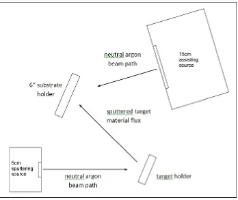
Figure 3-2. Diagram of IBAD chamber and components...98
Figure 3-3. Custom-built stainless steel substrate holder for Ti substrates ...99
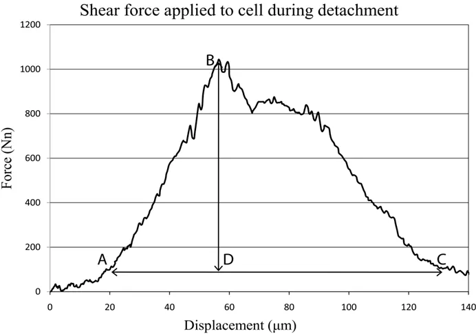
Figure 3-4. Example of force–displacement curve obtained from detachment of a single cell adhered to coating surface ... 104
Figure 3-5. Series of images captured from video during cell detachment process. Tip comes into contact with cell (A) shear force is applied to cell as X-Y stage is moved right (B) cell is fully detached as tip has moved across cell adhesive area (C)... 104
Figure 3-6. Linear regression for silver content vs. absorbance at 550nm ... 109
Figure 3-7. TEM cross-sectional micrographs of FGHA-Ag1, FGHA-Ag2 and FGHA-Ag3 coatings ... 111
Figure 3-8. Summary of cell detachment shear force measurements, showing average shear force (normalized by cell adhesive area) applied to cells to detach from the surface ... 113
Figure 3-9. Optical micrographs of sample surfaces A) FGHA coating (top left), B) FGHA-Ag1 coating (top right), C) FGHA-Ag2 coating (bottom left), and D) FGHA-Ag3 coating (bottom right) after 24-hour cell culture ... 116
Figure 3-10. Optical micrographs of sample surfaces A) FGHA coating (top left), B) FGHA-Ag1 coating (top right), C) FGHA-Ag2 coating (bottom left), and D) FGHA-Ag3 coating (bottom right) after 4-day cell culture ... 117
xi
Figure 3-12. Average number of MC 3T3 osteoblast cells counted on each of coating
surface at different incubation times. ... 119
Figure 3-13. Relative viability of cells by WST-1 assay ... 120
Figure 3-14. Release of Ag+ ions from each of the Ag-doped FGHA coatings immersed in USP water over time. ... 121
Figure 3-15. Surface roughness average (Ra) of each coating surface measured before and after immersion in culture medium. ... 122
Figure 4-1. PEEK rods of 1 ft length and ½” diameter before cutting ... 130
Figure 4-2. PEEK substrates of ½” diameter, ¼” height ... 131
Figure 4-3. Grinding and polishing station (Buehler) ... 131
Figure 4-4. Sonic cleaner (Buehler) ... 132
Figure 4-5. RF plasma barrel reactor ... 133
Figure 4-6. Hydroxyapatite sputter target [Kurt J. Lesker Co.] ... 134
Figure 4-7. Yttria-stabilized zirconia sputter target [Kurt J. Lesker Co.]... 135
Figure 4-8. Image of RF Magnetron Sputtering system at NNF Cleanroom NCSU... 138
Figure 4-9. Image of inside of RF Magnetron Sputter Chamber... 139
Figure 4-10. Surface Profilometer (Veeco Dektak 150) ... 144
Figure 4-11. Schematic diagram of stud-pull coating adhesion tester... 146
Figure 4-12. Image of stud-pull coating adhesion tester. ... 146
Figure 4-13. HA deposition rate vs. RF Power ... 151
Figure 4-14. HA deposition rate vs. Time ... 152
Figure 4-15. Coating thickness vs. time for YSZ and HA targets ... 154
Figure 4-16. Plot of plasma treatment time versus coating adhesion strength ... 157
xii
Figure 4-18. Coating pull-off area for partially delaminated coating ... 160
Figure 4-19. Optical micrograph of as-deposited coating top surface ... 162
Figure 4-20. Optical micrograph of microwave-annealed coating top surface ... 163
Figure 4-21. Optical micrograph of coating removal caused by microwaving ... 164
Figure 4-22. Optical image of coating ablation by KrF laser ... 165
Figure 4-23. Optical image of top coating surface after microwave anneal... 166
Figure 4-24. SEM Image of as-deposited YSZ/HA coating and PEEK substrate ... 167
Figure 4-25. SEM Image of as-deposited YSZ/HA coating cross-section ... 169
Figure 4-26. SEM images of A) YSZ and B) HA coatings separately ... 170
Figure 4-27. SEM image of HA/YSZ coating cross section after hydrothermal treatment ... 172
Figure 4-28. SEM image of HA/YSZ coating cross section after microwaving... 173
Figure 4-29. High magnification SEM image of microwave-annealed YSZ/HA coating cross-section ... 174
Figure 4-30. XRD Spectrum of as-deposited YSZ/HA coating on PEEK substrate ... 176
Figure 4-31. XRD Spectrum of 48-hour hydrothermally-annealed YSZ/HA coating .... 177
Figure 4-32. XRD Spectra of HA/YSZ coating after microwave annealing ... 178
Figure 4-33. FTIR Spectra on various surfaces ... 180
Figure 4-34. Initial osteoblast cell attachment to sample surfaces ... 183
xiii
LIST OF TABLES
Table 1-1. Mechanical properties of human hard tissue ...10
Table 2-1. Typical physical and mechanical properties of PEEK ...33
Table 2-2. Properties of medical-grade PEEK resins ...38
Table 2-3. Physical and Mechanical Properties of unfilled and CFR-PEEK compared with UHMWPE and PMMA ...46
Table 2-4. Selected properties of YSZ thermal barrier coating ...79
Table 2-5. Hydrothermal parameter for annealing of HA thin films ...89
Table 2-6. Laser parameters for annealing of HA thin films ...91
Table 3-1. Deposition parameters for Ag-doped FGHA coatings ... 100
Table 3-2. Composition of FGHA coatings as determined by XPS ... 101
Table 4-1. RF Magnetron Sputtering Deposition Parameters ... 137
Table 4-2. Deposition rates for YSZ and HA coatings ... 154
Table 4-3. Coating adhesion strength on PEEK substrates of varied surface roughness ... 155
Table 4-4. Effect of plasma treatment on coating adhesion strength ... 156
Table 4-5. Coating Adhesion strength before and after heat-treatment methods... 158
Table 4-6. Summary of Coating Adhesion Tests ... 161
Table 4-7. Crystalline peaks identified in as-deposited YSZ/HA coating ... 176
Table 4-8. Crytalline peaks identified in hydrothermal-annealed YSZ/HA coating .. 177
xiv
LIST OF ABBREVIATIONS
CFR – carbon fiber-reinforced CT – computed tomography CVD – chemical vapor deposition DSC – differential scanning calorimetry EDX – energy dispersive X-ray spectroscopy FGHA – functionally-graded hydroxyapatite FTIR – Fourier transform infrared spectroscopy HA – hydroxyapatite
HEPM – human embryonic palatal mesenchyme IBAD – ion beam assisted deposition
MRD – magnetic resonance imaging ORNL – Oak Ridge National Laboratory PAEK – poly-aryl-ether-ketone
PEEK – poly-ether-ether-ketone PET – poly-ethylene-terephthalate PLD – pulsed laser deposition PLLA – poly-L-lactic acid
PMMA – poly-methyl-methacrylate PS – poly-styrene
xv SEM – scanning electron microscopy
1
CHAPTER 1: INTRODUCTION
1.1. Spinal deformities, diseases and instability
Back pain is now one of the most prevalent and costly health problems in the world, resulting in more lost productivity than any other medical condition [1,2,3]. Approximately 85% of people in the United States report having back pain at some point in their lives [4]. Although many instances of back pain are temporary, chronic back pain is an increasing problem; one study reports that patients suffering from chronic back pain increased from 3.9% to 10.2% between 1992 and 2006 [5]. Conditions causing such problems include degenerative disc disease, spinal disc herniation, discogenic pain, spinal tumor, vertebral fracture, scoliosis, kyphosis
(Scheuermann’s disease), spondylolisthesis, spondylosis, posterior Rami Syndrom, and other degenerative spinal conditions. In all of these conditions, the cause of pain and instability can be traced to one or more problematic spinal segments; a spinal segment consists of two vertebrae, separated by an intervertebral disc.
Approximately 25% of those who suffer from these conditions will undergo spinal surgery. In many cases, the problems arising from an instable spinal segment can be resolved by a procedure known as spinal fusion. Spinal fusion is the surgical
2
procedures in the United States grew from 121,400 to 281,300 between 1990 and 2003. The growing need for spinal surgery instrumentation and fixation devices has sparked increased research aimed at advancing materials used in these applications in recent years. As a result of the increased demand, the production of many variations of spinal fusion cages by several implant manufacturers has grown rapidly over the last 20 years; the global market for spine implants has been reportedly increasing at a rate of over 20% per year [7].
1.2. Biomedical implants used in spinal fusion procedures
While implant design and manufacturing technology has improved over the past few years, several problems still exist and failed spinal fusion procedures are not uncommon. Among adults undergoing surgery for spinal deformations, 9% of patients will undergo a subsequent revision procedure at some point in their lives [8]. Common reasons for reoperation include pseudoarthrosis (non-fusion of the two vertebrae often due to an ineffective spinal fusion implant), painful or protruding implants, and implant removal. Because implant failure is one of the primary causes leading to the need for revision surgery, the improvement of current spinal implants can result in a
significantly higher success rate in spinal surgery and greatly reduce the costs, health risks and patient discomfort that arises from additional surgical procedures [8].
3
procedures aimed at stabilizing vertebral segments in order to correct segmental dysfunction or instability. Early spinal implants consisted of pedicle screws and small plates, secured to the two adjacent vertebrae of the problematic spinal segment to limit motion. These screws and fixation plates were metallic, constructed of either stainless steel or cobalt-chromium alloys. While they were successful to a degree in limiting lateral motion, these fixation systems were problematic in that they failed to prevent the unstable spinal segment from experiencing the vertical compression forces transmitted through the spine, and this led to very long recovery times and often to failure of the fusion procedure altogether.
4
application and began clinical testing in 1989 [9,10]. Based on successful data from these trials, the United States Food and Drug Administration approved these titanium cages for posterior interbody “standalone” use in 1996, and have since also approved these cages for anterior interbody placement [9].
Several varieties of the interbody fusion cage now exist including the Harms cage, Ray cage, Pyramesh cage, InterFix cage, and Lordotic LT cage, all of which are made from titanium; the SynCage, made from Polyetheretherketone, the Brantigan cage, made from carbon fiber; and the Cortical Bone Dowel, which is cut from allograft femur [105]. The cages can be packed with different types of bone graft material in order to promote arthrodesis (joint fusion).
5
The PROT Lumbar Cage (shown above) is just one of many designs of lumbar interbody fusion cages, which are used in the fusion of vertebrae in the lumbar (lower back) region of the spine. As seen in Figure 1-1, spinal fusion cages are often designed with macroscopic surface features, such as threaded columns or ridged surfaces, in order to enhance the mechanical bonding (interlocking) of newly formed bone to the surface of the implant.
Figure 1-2. Spinal fusion cage inserted between two vertebrae in the lumbar spine [12]
Shown above, the spinal fusion cage is implanted in the place of a deteriorating
intervertebral disc during spinal surgery. In many cases, the hollow spinal fusion cage is packed with bone graft to promote bone in-growth and to speed the fusion process between the adjacent vertebrae. A bone graft refers to bone transplanted from a donor
Healthy
intervertebral disc
Spinal fusion cage, (packed with bone graft to promote bone growth) replacing problematic inteverebral disc
Two vertebrae to be fused together Fusion plate
secured to both vertebrae to
6
site to a recipient site; the transplanted bone can originate from several different sources including:
1. Autologous (or autogenous) bone grafting refers to utilizing bone obtained from the same patient receiving the graft. Bone is harvested from non-essential bones, such as from the iliac crest (pelvic rim), the fibula, the ribs, the mandible and even parts of the skull. Block grafts, in which a small block of bone is placed whole in the area being grafted, most often use autogenous bone because there is less risk of the graft rejection due to the graft originating from the patient's own body [13]. A negative aspect of autogenous bone grafts is that an additional surgical site is required [14].
2. Allograft bone is also taken from human bone, however the difference is that allograft is harvested from an individual other than the one receiving the graft. Allograft bone is taken from cadavers that have donated their bone to be used for living people in need of bone transplants. Allograft bone comes in three forms: 1) fresh or fresh-frozen bone; 2) freeze-dried bone allograft (FDBA); 3) demineralized freeze-dried bone allograft (DFDBA) [15].
7 1.3. Biocompatibility
Besides the mechanical capability of spinal fusion implants to provide load sharing, maintain intervertebral disc height and to withstand deformation in order to allow fusion of an instable spinal segment, a primary requirement of material used in spinal fusion cages is a high degree of biocompatibility. Biocompatibility can be defined as “the ability of a material, device or system to perform without a clinically significant host response in a specific application” [7]. While this term is rather broad,
biocompatible materials can be further subdivided into being either bioactive or bioinert. Bioactive materials are those which positively interact with the surrounding tissue on a biological level, while bioinert materials, on the other hand, produce no biological interaction on their own and are simply tolerated by the surrounding tissue. Most materials which meet the mechanical requirements to be used as implants are only bioinert as a result of their chemical dissimilarity to human tissue. For this reason, a great deal of research is directed towards creating a bioactive surface on these
bioinert materials through the use of surface modifications, such as coating with a different, bioactive material.
8
formation of new bone. The types of cells that are involved in the formation of new bone are listed below:
Osteoblasts: bone-forming cells that produce alkaline phosphatase,
an enzyme involved in mineralization of bone, as well as in producing bone matrix proteins.
Osteoclasts: a type of bone cell that removes bone tissue by removing its
mineralized matrix and breaking up the organic bone. This process is known as bone
resorption.
These two types of cells, osteoblasts and osteoclasts, are responsible for controlling the amount of bone tissue in the body. Bone is a dynamic tissue, constantly being reshaped and reformed in response to mechanical stimuli, or the lack thereof. Osteoblasts are in charge of production of matrix and mineral, and osteoclasts break down the tissue.
Fibroblasts are a type of cell that synthesizes the extracellular
matrix and collagen, the structural framework for human tissues. Fibroblasts are the most common cells of connective tissue in animals; they are a type of stem cell that can mature into many other types of cells, including osteoblasts or osteoclasts.
9
The above terms describe the biological compatibility of orthopedic and dental implants. Equally important is the mechanical compatibility of the implant. While many materials are sufficiently strong to meet the mechanical requirements of a specific application, it is critical to select a material that does not greatly exceed the strength and stiffness of the surrounding bone in order to avoid stress shielding. Stress
shielding is a phenomenon by which a higher stiffness implant interferes with normal transmission of applied load, bearing more of the load and reducing the amount of load that surrounding bone would normally experience. This removal of mechanical
stimulus results in reduction of density and eventual deterioration of the surrounding bone following Wolff’s Law, which states that bone constantly remodels itself in response to applied loads [20]. In this aspect, it is detrimental to have an implant of much higher stiffness relative to the adjacent to bone, and so materials must be selected that closely match the mechanical properties of bone are desired. Some of the
10
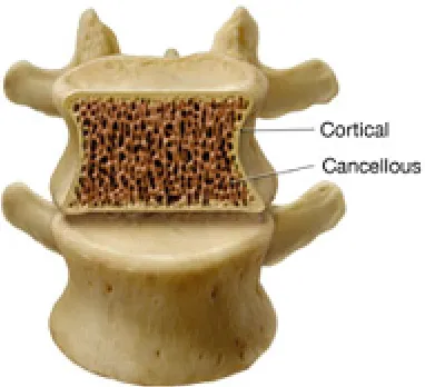
Table 1-1. Mechanical properties of human hard tissue
Material Elastic Modulus (GPa)
Tensile Strength (MPa)
Cortical bone 15-20 130 MPa
Cancellous bone 0.3 15
Enamel 80 11.5
Dentin 20 44
As seen in Figure 1-3, the vertebra is a cellular structure, comprised of a high
percentage of cancellous bone; which has very low stiffness. Considering its mechanical properties as a composite material, the vertebrae is quite susceptible to stress
shielding.
11 1.4. Materials used in spinal fusion cages
As described previously, the first standalone spinal fusion cages for human applications were developed by George Bagby in 1989 and were constructed of titanium [10]. Throughout the early stages of clinical application and development of varied geometries of the spinal fusion cage, titanium remained the material of choice for construction of the cage. Titanium was initially chosen because of its proven success in orthopedic implants due to its excellent biocompatibility and mechanical properties which are suited for load-bearing applications. Titanium and titanium alloys possess favorable properties of corrosion resistance, biocompatibility (through the formation of a TiO2 surface oxidation layer), low elastic modulus (compared with other metals) and high strength-to-weight ratio [21]. Titanium is used in several load-bearing orthopedic and dental implants including femoral stems of hip replacements, fracture fixation plates, bone screws and pins, dental posts, and many others. However, in the application of spinal fusion cages, titanium has been shown to have two distinct disadvantages:
12
GPa), a soft, cellular-structured bone that resists shear forces and acts to absorb shock within the spinal column.
2. The lack of radiolucency of titanium; titanium, like all metallic materials, is not transparent to radio waves, making radiographic assessment of the degree of bone fusion within the interbody fusion cage a problem for surgeons. Clinical diagnostic imaging tools, including X-rays and computed tomography (CT) scans are obstructed by traditional titanium fusion cages, resulting in the evaluation of
arthrodesis (joint fusion) within a titanium cage difficult or impossible [22]. Similarly, titanium produces metallic artifacts in magnetic resonance imaging (MRI). These limitations with respect to clinical assessment during the fusion process represent a significant problem for surgeons and patients, resulting in unnecessarily long recovery times and failure to identify problems with the fusion procedure (mainly
pseudoarthrosis) as they occur.
In order to overcome the limitations of spinal fusion cages constructed from titanium, high strength polymer materials have recently been utilized [105].
13
(PEKEKK) [105]. Due to a more stable supply and a higher compatibility with
reinforcing agents, such as carbon fiber, PEEK became the optimal choice as a polymeric material for use in spinal fusion cages. PEEK possesses numerous characteristics which make it an ideal choice for use as a load-bearing biomedical implant material; an elastic modulus (3.6 GPa) close to that of human bone, high melting temperature (340oC), excellent chemical stability, resistance to radiation used in sterilization procedures, transparency to radiowaves, ability to increase mechanical strength by fiber
reinforcement (4~20 GPa, depending on fiber volume fraction), etc. (Further details of PEEK are provided in Section 2.1).
Beginning in the mid-1990s, spinal fusion cages constructed from PEEK and carbon-fiber-reinforced PEEK (CFR-PEEK) were accepted by the FDA for human use and studied in clinical trials. PEEK biomaterials now have almost twenty years of successful clinical history in load-bearing spinal fusion cages and are now being evaluated for further demanding spinal applications such as posterior dynamic stabilization and total disc replacement [105]. While spinal fusion cages are still manufactured from both titanium and PEEK, an increasing number of implant developers have switched their focus from titanium to PEEK. For example, the
developers of the Wallis posterior dynamic stabilization system have converted their titanium interspinous component to PEEK [23]. It is expected that with the
14 1.5. Hydroxyapatite coatings
While titanium and PEEK have been shown to possess excellent mechanical properties and chemical stability even in the harshest of conditions, the bioinertness of these materials dictates that they do not actively participate in forming functional chemical bonds with surrounding tissue, as a bioactive material would; therefore recent research has been focused on improving the bioactivity of PEEK implants with respect to osseointegration. Hydroxyapatite (HA) [Ca10(PO4)6(OH)2] and other calcium
phosphate coatings have been shown to promote rapid osseointegration on metallic dental and orthopedic implants, which results in faster and superior implant
stabilization [24, 25, 26] Hydroxyapatite is preferred in bioactive coatings over other calcium phosphate phases because of its chemical similarity to bone (bone is comprised of approximately 70% of biological hydroxyapatite) and because of its low rate of dissolution. Details of hydroxyapatite are described fully in Section 2.2.1.
While possessing excellent biocompatibility, bulk hydroxyapatite is very brittle due to its ceramic nature, and cannot be used as the primary component of load-bearing implants; therefore, HA is used as a coating on traditional metallic materials such as titanium, cobalt-chromium, and stainless steel, and recently on polymeric materials such as polyetheretherketone (PEEK) to increase biocompatibility. Several studies have demonstrated the effect of hydroxyapatite coatings on improving bioactiviy of
15
increased bone apposition and increased differentiation of mesenchymal cells to osteoblast cells compared with control surfaces [30]. This is thought to be due to an increase in adsorption and production of proteins on HA surfaces, higher affinity of osteoblast cells to bone-like chemistry of HA, and increased crystal growth and matrix mineralization of osteoblast cells, once attached to the HA surface (due to the presence of Ca and P ions needed to form hard bone mineral)[30].
Hydroxyapatite coatings first received regulatory acceptance for human use in 1991 and have exhibited excellent results from clinical studies since then [31]. Early use of HA coatings in the 1990s was primarily in the application of hip implants; the femoral stem component of the implant, constructed from titanium, was coated with HA using the plasma spray method [31]. The strong fixation between implant and bone that resulted from a greater affinity of bone forming cells, called osteoblasts, to attach to the hydroxyapatite surface compared with bare titanium allowed for implants to be
inserted without the use of bone cement to fix the implant in place. Cementless
implantation is a preferred option due to the fact that some patients are allergic PMMA bone cement, as well as the recent discovery of bone cement implant syndrome (BCIS), in which serious complications can be caused by degradation of bone cement [32].
Plasma spraying is the current commercial method used to produce
16
onto the substrate surface. This method is used because of its high deposition rate, low cost, and ease of application. Despite concerns about coating delamination, plasma spraying was chosen as the preferred method of coating in the early 1990s because it was an established technology at the time, it was cost-effective, and it was seen as the
most easily reproduced approach [31]. Plasma-sprayed HA coatings can promote
greater direct bone attachment and improve bonding strength at the bone–implant interface when compared with uncoated titanium implants [33]. However, numerous problems with plasma-sprayed HA coatings have been cited, including weak bonding strength at the coating–metal interface, variation in structural and chemical properties, and nonuniformity in coating density [34, 35]. Because of these limitations, many alternative methods for deposition of HA have been investigated, including radio frequency magnetron sputtering, electron beam deposition, pulsed laser deposition, sol-gel spinning, precipitation from solution, hot isostatic pressing and others. Further description of the methods used to deposit hydroxyapatite coatings is described in Section 2.2.3.
1.5.1. Functionally Graded Hydroxyapatite (FGHA) Coatings
The Advanced Materials Research Laboratory (AMRL), under the direction of Dr. Rabiei in the Mechanical and Aerospace Department at North Carolina State University (NCSU), has been involved in the research and development of improved
17
described, crystalline hydroxyapatite is the least soluble of the calcium phosphate phases in physiological fluid and is therefore able to provide the most long-term stability when used as a coating for biomedical implants. However, dissolution of calcium phosphates is beneficial in early stages after implantation in order to provide Ca2+ and PO43- ions which accelerates new bone growth. In this aspect, amorphous calcium phosphates are more bioactive than crystalline hydroxyapatite but have poor long-term stability as they become completely dissolved within weeks after
implantation, causing the bare implant surface to be exposed to the surrounding body fluid [37]. Due to this competition between long-term stability and initial bioactivity, a CaP coating with uniform crystallinity cannot satisfy both demands. The optimal
dissolution behavior of a calcium phosphate coating is one which dissolves rapidly upon initial introduction into the physiological environment and then gradually dissolves more slowly over longer time periods in order to retain a layer of coating on the
implant surface. In order to solve this problem , Dr. Rabiei has developed a functionally graded hydroxyapatite (FGHA) coating, which exhibits a mostly amorphous top coating layer, a semi-crystalline middle layer, and a mostly crystalline layer at the substrate surface [33, 38, 39]. This coating is achieved using ion beam assisted deposition (IBAD) with in situ substrate heating in order to form various degrees of crystallinity by
adjusting substrate temperature over the course of the deposition. The FGHA coating has been previously studied and optimized in terms of mechanical properties,
18
and mechanical properties when compared with commercial plasma-sprayed coatings and HA coatings produced by other methods [63].
The improvement in bioactivity of the FGHA coating compared with commercially pure titanium was measured using cell spreading and
immunofluorescence integrin assays, performed using ATCC CRL 1486 human
embryonic palatal mesenchyme (HEPM) cells, an osteoblast precursor cell line [40]. It was determined that the FGHA coating promoted increased cell attachment and spreading compared to the pure titanium surface. Shown in Figure 1-4, more HEPM cells are found on the FGHA surface compared with titanium and exhibit a higher degree of spreading of the extracellular matrix, indicating a healthier state.
19
1.5.2. Hydroxyapatite coatings doped with antibacterial agents
Heavy metals such as lead, mercury and silver are known to exhibit a toxic effect on some bacteria, viruses and fungi [41]; among these, only silver is non-toxic (in low doses) to humans. The mechanism by which Ag reduces bacteria is not yet fully understood, but it is thought to involve protein inactivation of the bacterial cells and DNA association, in which Ag ions bond to bacterial DNA and eliminate its ability to replicate [41,42,43]. Silver has been used as an antibacterial agent for many years in applications such as topical gels, wound dressings, surgical masks and textiles.
In the field of biomedical implants, infection represents one of the primary causes for implant failure and subsequent revision surgery [44]. Risk of infection is highest immediately after implantation and gradually decreases within the following weeks. Staphylococcus aureus and Staphylococcus epidermidis are the two most common strains of bacteria that cause infection after implant surgery, representing approximately 80% of infections following orthopedic implant procedures [44].
Because Ag is known to be toxic to these strains of bacteria, Ag is has been incorporated into bioactive coatings and bone cements for biomedical implants within the last few years [44,45]. For HA coatings specifically, Ag is doped into the coatings by methods of ion exchange, thermal evaporation and co-sputtering, typically in concentrations of less than 10 wt % [44,46].
Recently, the Advanced Materials Research Laboratory (AMRL) at North
20
graded hydroxyapatite (FGHA) coatings by incorporating small percentages of Ag into the FGHA coatings during the deposition process [175,182,40]. The method for
producing Ag-doped FGHA coatings has already been established; however, the dissolution behavior and biological response to these coatings still needs further
studies. The first part of this research seeks to investigate the dissolution and biological response to the Ag-doped FGHA coatings, as well as to correlate these findings to the compositional and microstructural properties of the coatings.
1.6. Yttria-stabilized zirconia intermediate layer
Yttria-stabilized zirconia (Y2O3 minor component, ZrO2 major component), or YSZ, while not bioactive, is a biocompatible material that has been used in some studies to improve the mechanical qualities of hydroxyapatite coatings [47,48,49,50]. YSZ, traditionally used as a thermal barrier coating to coat high-temperature components, has been shown to toughen hydroxyapatite coatings when used as second phase material within the coating [47,50], and to increase bond strength of hydroxyapatite coatings when used as a precursor layer, applied directly to the substrate material before the deposition of the hydroxyapatite coating layer [48]. The overall
21
polished substrate, resulting in stronger mechanical bonding of the subsequent HA layer; (3) when used as a minor phase constituent in the HA coating layer, the YSZ particles serve as a reinforcing agent, increasing toughness of the coating and resulting in increased cohesive strength of the composite coating.
In this research, yttria-stabilized zirconia (7% Y2O3 / 93% ZrO2) is proposed as an intermediate layer, between the PEEK substrate and the hydroxyapatite top coating layer. The YSZ layer is expected to provide the following benefits:
1. To provide some degree of heat shielding to the PEEK substrates during post-deposition heat treatments for the purpose of forming a crystalline HA phase in the top coating layer. (Post-deposition heat treatment of the coating will be discussed in Section 1.8).
2. To increase the overall coating adhesion strength to the PEEK substrates as compared with HA coating alone.
1.7. Deposition of HA/YSZ bilayer coating by RF magnetron sputtering
22
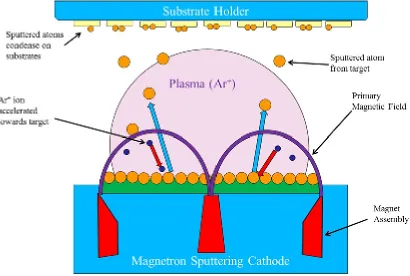
the energetic particles to bombard the sputter target in the sputter deposition process. Sputter deposition takes place in a reduced pressure environment (high vacuum
chamber) so that ejected atoms condense onto the substrate without being hindered by collisions with other gas molecules. (Further description of sputter deposition in Section 2.2.3)
Among the many techniques available to produce HA coatings, sputtering possesses unique advantages that allow for the highest quality of coatings to be produced with the most control over coating properties. One aspect of sputter deposition that is particularly important in this research is that materials with very high melting points, which would be problematic or impossible to deposit using thermal or electron-beam evaporation, are easily sputtered because they are physically
23
materials for a number of reasons; for one, ion bombardment of the substrates is often used as a “pre-cleaning” step that serves to remove contaminants and adsorbed gases and produces a reactive surface that is more susceptible to atomic bonding; secondly, the heat and impact energy caused by energetic ions striking the surface of the
substrate enhances bonding due to increased diffusion of sputtered atoms into the interfacial region; finally, the very thin (usually less than 2 µm) and dense coatings produced by sputtering are less affected by mismatches in thermal expansion and are also less susceptible to cracking compared with thicker ceramic coatings, due to the presence of fewer large cracks [52].
24
Figure 1-5. Schematic diagram of RF Magnetron sputtering process
1.8. Crystallization of hydroxyapatite coating on PEEK
25
coating layer, a post-deposition heat treatment step is necessary to transform the as-sputtered amorphous HA into crystalline HA (or other crystalline CaP phases).
Traditional crystallization of HA films involves annealing at temperatures above 600oC for at least one hour. Due to the comparatively low melting point of the substrates used in this research (PEEK has a melting temperature of approximately 340oC),
conventional oven annealing is not a viable option. To overcome this limitation, three alternative methods for forming crystalline HA are proposed in this study, which have
the potential to cause an amorphous crystalline phase change by either lowering the
activation energy necessary for the phase transformation to occur or by selectively heating only the HA coating, leaving the PEEK substrate relatively unheated. The methods which will be attempted are:
26
[55,56]. Transparent materials allow microwaves to pass through with little or no attenuation; opaque materials reflect microwaves without absorbing; and absorbing
materials (dielectrics) absorb and are easily heated by microwaves [55,56].Based on
the electromagnetic absorption characteristics of the coating and substrate materials used in this research (HA is dielectric, YSZ is opaque, and PEEK is transparent), microwave heating appears to be an excellent choice for selective heating of the HA coating in order to cause crystallization [57]. It is expected that that microwave heating can achieve selective heating of the HA coating layer without causing significant heating of the PEEK substrate.
27
amorphous calcium phosphate coatings of approximately 250 nanometers produced by sputter deposition were crystallized in HA by pulsed fluorine (F2) laser. In this research, crystallization of the amorphous sputtered HA coatings on PEEK substrates will be attempted using a pulsed krypton fluoride (KrF) laser.
3.Hydrothermal annealing is a process by which materials are exposed to elevated temperature and water vapor pressure by means of a saturated steam in a pressure vessel, such as an autoclave. As opposed to microwave heating and laser-induced crystallization, hydrothermal annealing is an alternative heating method which can cause crystallization of hydroxyapatiteat lower temperatures by lowering the activation energy required for the amorphous to crystalline phase change to occur. Activation energy is lowered by the combination of elevated temperature and high pressure water vapor. This is proposed to result from replenishment of missing OH groups with surrounding H2O molecules; HA thin films produced by high temperature processes or high vacuum processes tend to be hydroxyl-deficient detracting from their ability to form crystalline HA [61]. Previous studies have demonstrated that
hydrothermal treatment, at temperatures of 200oC or below, was effective in forming crystalline HA coatings from amorphous CaP coatings produced by plasma-spraying and sputtering methods [59,60,61,62]. (Hydrothermal annealing mechanism is
28 1.9. Objectives
The objectives of this project are two-fold:
1. Initially, functionally graded hydroxyapatite coatings doped with silver as
an antibacterial agent deposited on titanium substrates which have been previously developed and optimized [63] are to be evaluated in terms of microstructure, release of silver ions and biological response, including antibacterial effect and culture tests. Specific tests will include osteoblast cell count, cell attachment shear force measurement, silver release profile,
antibacterial test and cell viability tests.
2. The second objective, and primary focus of this project, is to process
bioactive hydroxyapatite coatings on polyetheretherketone (PEEK) substrates in order to improve biocompatibility of PEEK implants used in spinal surgery. The coatings will be processed using a physical vapor deposition (PVD) method; more specifically, radio-frequency magnetron sputtering. Due to the fact that hydroxyapatite coatings produced by physical vapor deposition are inherently amorphous, the coatings will be heat treated after deposition, using an
29
These expected benefits will be evaluated using various tests. The
mechanical properties of the coating will be measured using a coating adhesion stud pull-off test. The microstructure and crystalline features of the coating will be evaluated using scanning electron microscopy (SEM) of the coating cross sections. The microstructure and phase constituents will be evaluated by X-ray diffraction (XRD). The composition of coating will be quantitatively evaluated by X-ray photoelectron spectroscopy (XPS) and scanning electron microscopy equipped with energy dispersive spectroscopy (SEM-EDS). Finally, culture tests will be performed to evaluate the bioactivity, antibacterial effect, and
30
CHAPTER 2: LITERATURE REVIEW
2.1. PEEK
Many types of polymeric materials are used in medicine, each having its own set of properties, making them suited to specific applications. Poly-ether-ether-ketone (PEEK) is a polymer with the molecular formula -(-C6H4-O-C6H4-O-C6H4-CO-)-n belonging to the subcategory of homopolymers. Homopolymers are composed of repeating units of only one molecular segment (or monymer), taking the form (A-A-A-A), as opposed to copolymers, made from more than one type of monomer and taking the form of (A-B-A-B), where A and B represent different monomers. Because PEEK is made up of many of these monomer units, the average molecular weight is high and varies between 80,000 and 120,000 grams per mole [64]. PEEK is a relatively new high performance polymer, belonging to the chemical family of PAEK resins.
Polyaryletherketones (PAEK) resins are a class of high performance polymers used in joint replacements and other long term implants due to their high chemical and mechanical resistance. PEEK, first synthesized in 1978, was initially used as specialty polymer in very few applications, such as in aerospace moldings and in aircraft and turbine blades (as a fiber-reinforced composite), due to its high cost; however, a stable supply and increasing number of providers has led to its use in other high-tech
31
is now the leading candidate for replacing metallic components in load-bearing biomedical implants, especially in orthopedic applications [64]. Currently, medical grade PEEK-OPTIMA® is manufactured by Invibio® and is used in the development of “implantable medical devices and pharmaceutical applications having blood or tissue contact for more than 30 days” [65]. Previously, “PEEK-Optima LT” (LT stands for long-term implantation) was produced by Victrex [65,68]. This material has been approved by the Food and Drug Administration (FDA) and is USP Class VI approved [68].
2.1.1. Physical and chemical properties of PEEK
Implantable-grade PEEK, also known as PEEK-OPTIMA®, is a semi-crystalline thermoplastic that possesses superior strength, stiffness and toughness, compared with other biocompatible polymers, while being able to retain these properties through repeated sterilization procedures by steam, radiation and chemical methods [65]. Thermoplastics are polymers that soften or melt when heated and harden when cooled. Thermoplastic polymers consist of long polymer molecules that are not connected by cross-links; thermosets, on the other hand, are polymers which are permanently cured when heated, forming crosslinks that prevent them from being softened or remelted upon heating. Thermoplastics are often supplied as granules and heated to permit fabrication by methods such as molding or extrusion. Besides PEEK, other
32
The repeat unit in the molecular chain of PEEK consists of two ether groups followed by a ketone group, written as -(-C6H4-O-C6H4-O-C6H4-CO-)-n and shown in chemical notation below:
Figure 2-1. PEEK molecular repeat structure [66]
The PEEK polymer is formed by a method known as “step-growth polymerization,” and is the product of the dialkylation of bisphenolate salts [66]. A typical reaction of this type is that of 4,4-difluorobenzophenone with the disodium salt of hydroquinone, which is generated in situ by deprotonation with sodium carbonate. This reaction is shown below:
Figure 2-2. Polymerization Reaction of PEEK [67]
33
The ASTM standard (ASTM F 1579 “Standard Specification for
Polyaryletherketone (PAEK) Resins for Surgical Implant Applications”) classifies the chemical and mechanical properties of PAEK, to which PEEK belongs. Typical
properties of PEEK are given in the table below:
Table 2-1. Typical physical and mechanical properties of PEEK [68]
Property Value
Density (g/cm3) 1.32
Elastic Modulus (GPa) 3.7
Tensile Strength (MPa) 100
Elongation (%) Up to 60
Melting Temperature (oC) 334
34
35 Figure 2-3. PEEK orthorhombic unit cell [105]
As previously mentioned, PEEK usually consists of 30 to 35% crystallinity, however crystalline content can vary between 0 and 40%, depending on its thermal processing
[105]. For example, purely amorphous PEEK films can be formed by supercooling thin
samples (t < 1mm) by quenching from the melt into cold water [71]. Similarly, amorphous PEEK regions (called “amorphous skins”) are also seen on the outer
surfaces of injection-molded components, when the mold is cooled too quickly from the melt [105].
36
molding facilitates construction of PEEK spinal implants without the need for an extra machining step. PEEK has a glass transition temperature of approximately 143oC; the glass transition temperature in polymers refers to the temperature above which molecular chains are able to slide past one another, resulting in a softer, rubbery polymer, whereas below the glass transition temperature, the material is hard and rigid. Thermal properties of polymers are typically measured using differential scanning calorimetry (DSC), which measures the amount of heat need to cause a temperature change within a material.
37
A DSC trace of PEEK (shown in Figure 2-4) displays its thermal properties of glass transition temperature, Tg, which separates the “glassy” and “rubbery” regimes, and the melt temperature, Tm. The glass transition temperature at approximately 143oC, can be seen by the change in slope of the heat input/temperature curve; the melting point, at approximately 340oC, can be observed as a large spike, corresponding to the isothermal phase change from solid to liquid. Mechanical properties of PEEK refer to its behavior at temperatures below the glass transition temperature.
PEEK in its “natural”, non-reinforced form has a light tan or beige color in appearance, which make it aesthetically more compatible than metallic materials for biomedical applications such as exposed dental implants and components of prosthetic limbs. Carbon-fiber reinforced PEEK has a darker, grey appearance, which becomes darker with increasing volume fractions of carbon fiber.
2.1.2. Processing of PEEK
The polymerization of PEEK, shown in Figure 2-3, produces the PEEK resin, referring to pure PEEK powder. Resins for medical-grade PEEK, or PEEK-OPTIMA®, is manufactured under strict quality-control procedures to meet ISO standards 9001:2000 and 13485:2003 in a cleanroom environment in order to reduce the risk of
38
forms, depending on the processing that will be used, and is categorized based on its molecular weight and flow characteristics; it is necessary to know these factors in order for the manufacturer to select a suitable raw material for a specific forming process. Grades of resin, and their respective applications, are shown in Table 2-2.
Table 2-2. Properties of medical-grade PEEK resins [64]
Property 450 PEEK Resin 381 PEEK Resin 150 PEEK resin Invibio® PEEK
designation Optima LT1 Optima LT2 Optima LT3
Melt flow index 3.4 4.5 36.4
Molecular weight 115,000 g/mol 108,000 g/mol 83,000 g/mol
Grade characteristics/
Applications
General purpose grade; majority of machining and injection molding
processes
Reduced viscosity and good melt strength; used in extrusion of
thin-walled parts
Lowest viscosity; used in injection
molding of thin-walled parts
39 2.1.2.1. Extrusion
Extrusion describes the process of pushing or drawing a material through a die of fixed cross-section [72]. Extrusion is used in the production of PEEK rods, plates and fibers. During the extrusion process, PEEK granules or pellets are fed into a heated screw assembly that melts the raw material and pressurizes the melt; the molten PEEK is then forced through a heated die and then slowly cooled along the extrusion line [64]. This process can be carried out using conventional extrusion equipment and dies and is advantageous in terms of producing PEEK components with a very low variation of crystallinity percentage within different areas of the final product due to uniform heating. Extrusion is more commonly used to produce PEEK rods or plates that are subsequently machined into a final shape and used in medical devices, rather than for the production biomedical implants themselves [64].
2.1.2.2. Compression Molding
40
time required limit its use to low-volume products, prototyping, and production of large, industrial components with thick cross-sections [64].
2.1.2.3. Injection Molding
41 Figure 2-5. Injection-molded PEEK component [64]
Due to the variation in thickness across different areas of an injection-molded component, rates of cooling cannot be uniform for all regions of the part, which can result in variation of crystallinity within the solidified product; as seen in Figure 2-5, amorphous regions (lighter colored areas) can result within an injection-molded part due to rapid cooling. In order to prevent the rapid cooling that leads to this problem, mold temperatures must be precisely controlled and monitored.
2.1.3. Mechanical properties of PEEK
42
(if any). As such, it is necessary to know the resin grade, thermal processing history and fiber content in order to predict the mechanical behavior of a PEEK component.
Talbott et al. measured the mechanical properties of both unfilled and carbon-fiber reinforced (CFR) PEEK as a function of percentage of crystallinity using PEEK 150 powder resin as the raw material [74]. Samples of unfilled and CFR-PEEK were formed with crystallinities ranging from 0 to 40% by cooling from a melt at different rates. As expected, tensile strength, shear strength and compressive strength were increased by increasing the crystallinity of both the unfilled and CFR PEEK. In the unfilled samples, the elastic modulus was increased from 510 ksi (3.52 GPa) to 630 ksi (4.62 GPa) when crystallinity percentage was increased from 16 to 39%; shear modulus was increased from 175 ksi (1.21 GPa) to 205 ksi (1.41 GPa) over the same range [74].
43
to 3.2 ksi*in1/2 (3.52 MPa*m1/2) [74]. From these data, the authors were able to
formulate relationships for several mechanical properties with respect to crystallinity content of PEEK, useful over the range of 0 to 40% crystallinity.
Recent studies on 450 G (granule) PEEK material have investigated the plastic deformation behavior of PEEK samples at large strain values [75]. It was observed that unfilled PEEK has good ductility and is able to undergo large plastic deformation in both uniaxial tension and compression. At strain values below 0.03 PEEK exhibits a linear stress-strain slope; as strain is increased, there is a clear transition at the yield point, beyond which PEEK undergoes strain hardening and elongation over 50% at room temperature [75].
Experimental and finite element analysis experiments have established that PEEK-OPTIMA is a suitable material for load-bearing implants in the human body. While many of these studies describe the ability of carbon fiber reinforced-PEEK implants to perform in load bearing implants, few have investigated the use of non-reinforced (unfilled) PEEK in these applications. One recent study evaluated the performance of non-reinforced PEEK using quasi-static compressive testing, creep testing in simulated physiological environment and finite element analysis (FEA) in which spinal fusion cage geometries and materials (PEEK and Titanium) were
44
creep strain of less than 0.1% after 2000 hours of loading. Finite-element analysis demonstrated that while maximum strain on adjacent vertebrae due to insertion of a spinal fusion cage is more dependent on cage design than on material, PEEK spinal fusion cages resulted in slightly lower strain values than similar titanium cages.
2.1.4. PEEK composites
The elastic moduli of human cortical bone in the longitudinal and transverse directions are typically reported in the range of 16–23 and 6–13 GPa, respectively [77] The ability of a load-bearing implant to share applied stresses equally with surrounding bone and to transfer load continuously depends on how closely its mechanical
properties are to those of the surrounding bone. PEEK, which exhibits an elastic
modulus of 3.6 GPa, is much more closely matched to human bone than titanium, whose elastic modulus is approximately 100 GPa. However, with the use of reinforcing agents, PEEK biocomposites have been produced with elastic moduli that can be tailored to match exactly the stiffness of human bone. Several studies have shown that the stiffness and strength of PEEK can be increased with fiber reinforcement.
The most common form of PEEK composite is that of PEEK reinforced with carbon fiber. Since the introduction of PEEK as a biocompatible material, numerous studies have investigated the effect of various lengths, volume fractions and
orientations of carbon fiber reinforcements on the mechanical properties, wear
45
the purpose of strengthening PEEK is to raise its stiffness value to that of human bone, in order to provide a continuous, even load transfer between PEEK implants and adjacent bone; for example, PEEK may be modified with the addition of short carbon fibers to increase the elastic modulus from approximately 4GPa to approximately 18GPa and tensile strength from 100MPa to 230MPa of the base polymer [65]. Higher strength and stiffness values can be achieved by using longer fibers and higher volume fractions [74,105]. As is the case with most strengthening mechanisms, the increase in elastic modulus, tensile and shear strengths of PEEK by fiber reinforcement has a negative impact on its ductility and fracture toughness [74]; however, ductility and toughness are not decreased to an unacceptable level with normal volume fractions of fiber reinforcement.
While significantly weaker than titanium fusion cages of the same design, carbon-fiber reinforced cages exhibit sufficient mechanical strength to maintain disc space between vertebrae during the fusion process, and have shown to perform equally well in clinical trials [78].
46
Table 2-3. Physical and Mechanical Properties of unfilled and CFR-PEEK compared with UHMWPE and PMMA [105]
Property Unfilled
PEEK
30 % CFR-PEEK
68 %
CFR-PEEK UHMWPE PMMA
Molecular weight (g/mol) 80,000-120,000 80,000-120,000 80,000-120,000
2x10⁶ – 6 x10⁶
100,000– 800,000
Specific Gravity 1.3 1.4 1.6 0.93-0.95 1.2
Elastic Modulus
(GPa) 4 20 135 0.8-1.6 1.5-4.1
Tensile
Strength (MPa) 93 170 > 2,000 39-48 24-49
Elongation (%) 30-40 1-2 1 350-525 1-2
As can be seen from Table 2-3, the strength and strength-to-weight values for unfilled PEEK are already considerably higher than similar biocompatible polymers, and with the addition of carbon fiber reinforcement, PEEK composites can achieve strengths similar to titanium. Initially there were concerns about negative effects of carbon fiber released from composites containing short or chopped fibers on the response
47
A relatively new area of research in PEEK composites is the incorporation of HA particles with the goal of simultaneously adding strength and improving the
biocompatibility of PEEK and providing a degree of porosity for new bone in-growth [81,82,83,84]. Shown in Figure 2-6, PEEK can be filled with up to 40% HA particles using injection molding without interfering with the crystallization behavior upon cooling [81-84]. However, HA and other calcium phosphate have low affinity for PEEK surfaces which contributes to a poor interface between the PEEK matrix and the HA (or other CaP) particles or fibers; this phenomenon leads to a deterioration in strength of the composite with increased volume fractions of HA [84,86]. Also, the increase is bioactivity of these PEEK composites is debatable, with some studies showing an increase in bioactivity in vitro [81,85], while others have shown no increase in human osteoblast attachment compared with a pure PEEK surface [84,86].
48
2.1.5. Resistance to radiation, elevated temperature, and chemical sterilization
Long term stability of biomedical implants depends not only on their mechanical durability, but also on their ability to withstand exposure to sterilization procedures and physiological environments with degrading as well. This requires that implant materials be resistant to radiation, harsh chemicals and elevated temperatures. PEEK exhibits excellent stability in relation to these scenarios due its naturally unreactive chemical structure [105].
The physiological environment, in which biomedical implants spend their entire service life, is extremely harsh in terms of causing degradation of many materials. Body fluid is a highly oxygenated saline electrolyte solution with a pH of approximately 7.4 and a temperature of 98.6°F (37°C) [87]. The many types of salts contained in body fluid are highly corrosive to metals, and the addition of high ionic and protein concentraions can also be deleterious to many materials in terms of mechanical, chemical and electrical properties. PEEK, however, due to its “resonance stabilized chemical structure”, contains delocalized high orbital electrons along the entire macromolecule, causing it to be extremely chemically stable; for example, PEEK is not damaged by any solvents, with the only exception being highly concentrated (98%) sulfuric acid.
![Figure 1-2. Spinal fusion cage inserted between two vertebrae in the lumbar spine [12]](https://thumb-us.123doks.com/thumbv2/123dok_us/1336713.1166652/24.612.88.523.282.497/figure-spinal-fusion-cage-inserted-vertebrae-lumbar-spine.webp)
![Figure 2-8. Radiographs (a,b) and CT scans (c,d) of anterior cervical fusion using PEEK fusion cage [97]](https://thumb-us.123doks.com/thumbv2/123dok_us/1336713.1166652/72.612.103.354.78.407/figure-radiographs-scans-anterior-cervical-fusion-using-fusion.webp)
![Figure 3-1. Image of IBAD system at ORNL [63]](https://thumb-us.123doks.com/thumbv2/123dok_us/1336713.1166652/116.612.91.438.185.444/figure-image-of-ibad-system-ornl.webp)
![Figure 3-3. Custom-built stainless steel substrate holder for Ti substrates [63]](https://thumb-us.123doks.com/thumbv2/123dok_us/1336713.1166652/118.612.89.423.156.401/figure-custom-built-stainless-steel-substrate-holder-substrates.webp)