DC Motor Speed Control with PID Controller:
A Review
Shikha Singh1, Miloni Ganatra2, Hansa Shingrakhia3, Zalak Patel4 Assistant Professor, Dept. of EEE, Indus University, Ahmedabad, Gujarat, India1,2 Assistant Professor, Dept. of ECE, Indus University, Ahmedabad, Gujarat, India3,4
ABSTRACT: This paper presents different mechanisms used in controlling the speed of dc motor through PID
controller. In order to improve the efficiency for various industrial processes , PID controllers are mostly used due to their simple operation. Tuning of PID controllers can be done using various tuning methods and the mathematical model can be simulated in simulink , which helps in controlling the speed of the dc motor. With the help of Labview aided PID controller, the parameters of PID controller can also be adjusted so as to control the speed of dc motor. In addition to this, speed of the dc motor can be controlled using PID controller , generated by arduino program .
KEYWORDS: Dc Motor; PID Controller; Tuning Methods; Labview; Arduino
I. INTRODUCTION
Dc machines are electromechanical energy conversion devices which can operate as a dc motor or as a dc generator. Conversion of electrical energy from a dc supply system into mechanical energy of rotation and driving a mechanical load takes place through dc motor. There are various areas where a dc motor can be used, starting from small motor applications in toys, automobiles, food blenders etc. to the large motor applications in rolling mills, elevators etc. Some of the characteristics which makes dc motor to be widely used in industries are high starting torque, high response performance and wide speed control range. The speed of the dc motor can be controlled over a wide range by using different techniques. One of the mechanism used to control the speed of the motor is through PID controllers.
II. CONSTRUCTION OF DCMACHINE
A dc machine consists of a stator and a rotor with a uniform air gap in between. The stator, in case of dc machines, invariably carries the field windings and the rotor carries the armature windings.
I. Stator:- The stator is mainly constituted of field poles, yoke , interpoles, brushes, brush holders, end bell structure and bearings. The field poles supports the field windings, which produces the necessary magnetic field. The pole shoe is so designed so as to produce a uniform distribution of flux in the air gap. The yoke is a part of the frame and provides the return path for the flux from one pole to another. The interpoles and their windings are mounted on the yoke and are located in the interpolar region between the main poles. The rotating armature and the external circuit are connected through the brushes. Brushes are employed to collect current from the commutator and deliver it to the load.
Fig.1 Basic construction of D.c.Machine
Operation of dc machine as a motor:- If the armature terminals of a dc machine are connected to a dc voltage source, it begins to rotate and operate like a motor, converting electrical energy into mechanical energy. Construction wise, a dc motor is similar to dc generator. Dc motor has to operate in stringent environmental conditions, it has to be protected against moisture, fire hazards, chemical gases and mechanical damages. Therefore, the frame of dc motor is either fully or partially closed to provide sufficient protection.
Principle of operation of a dc motor:-When a current carrying conductor is placed inside a magnetic field , it experiences a force given by,
F= BIL newton.
Where B is the flux density in Wb/m2, I is the current in amperes flowing in the conductor, and L is the effective length of the conductor in metres. The direction of the force on the conductor can be determined by applying fleming’s left hand rule.
III. PROPOSED METHODOLOGY
The speed of the dc motor can be controlled using different controller. In this paper, speed is controlled by PID controller.
PID Controller
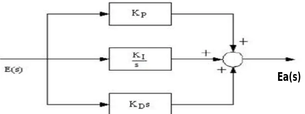
A PID controller produces an output signal consisting of three terms- one proportional to error signal, another one proportional to integral of error signal and third one proportional to derivative of error signal. The proportional controller stabilizes the gain but produces a steady state error. The integral controller reduces or eliminates the steady state error. The derivative controller reduces the rate of change of error.PID controllers have higher stability , no offset and reduced overshoot.
Fig 2. PID controller system block diagram
The relationship between the input E(s) and output Ea(s) can be formulated in the following as :-
Ea(s)= (Kp +KI/s + KDs)E(s)
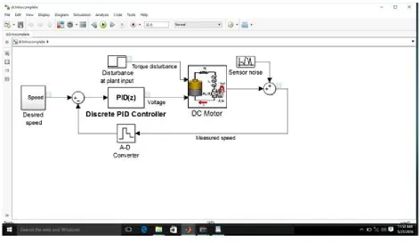
The dc motor speed control using PID controller system block diagram is shown in Fig 3.
Fig 3. DC motor speed control using PID controller system
1. Speed Control of dc motor with PID controller using Simulink:-PID controller can be designed and simulated
in simulink, to control the speed of dc motor.
2. Speed Control of DC motor using Labview aided PID controller:-There are many methods proposed for tuning
of PID controller. Some of the methods are discussed below.
Good Gain Method
Process reaction Open loop curve
Ziegler Nichols Closed Loop method
Skogestad’s Method
Genetic Control
Fuzzy Logic Control
The Good Gain method
Good Gain method is based on experiments done in a simulated or real control system. In this method, during the tuning phase, it is not required for the control system to be brought into sustained oscillations, unlike Ziegler-Nichols’method.
Fig.4 The Good Gain method for PID tuning is applied to the established control system.
The Ziegler-Nichols’ PID tuning procedure
Based on experiments executed on an established control loop which can be a real system or a simulated system, Ziegler-Nichols’ closed loop method is used to tune PID controller parameters.
The procedure for tuning of PID controller is as follows:
1. Try to bring the process as far as possible to the specified operating point of the control system. This is done to to minimize the chances of variables to reach limits during the tuning. By manually adjusting the control variable, with the controller in manual mode, the process can be set to the operating point, until the process variable is approximately equal to the setpoint. 2. By setting set Ti = ∞ and Td= 0, turn the PID controller into a P controller. Set proportional gain Kp= 0 initially. Set the
controller in automatic mode so as to close the control loop.
3. The proportional gain Kp should be increased until there are sustained oscillations in the signals in the control system.
3. Speed Control of dc motor using PID controller and arduino
Speed of the dc motor can be controlled by PID controller generated using arduino program. Arduinois a single-board
microcontroller designed to make the process of using electronics in multidisciplinary projects more accessible. The hardware consists of a simple open-source hardware board designed around an 8-bit Atmel AVR microcontroller, though a new model has been designed around a 32-bit Atmel ARM. The software consists of a standard programming language compiler and a boot loader that executes on the microcontroller. The program is loaded into the microcontroller and the analog outputs are connected to PID controller. The speed is sensed by the encoder and is compared with the reference value and the obtained error signal is projected over PID controller. The process continues till the errors are minimized.
IV. CONCLUSION AND FUTURE WORK
In this paper, designing of PID controller using matlab, labview and arduino is explained. By varying parameters and by tuning of PID controller , speed of dc motor can be controlled. Labview is a debugging tool. It is better for control application.MATLAB is better for data manipulation. Labview takes less execution time than MATLAB. Furthermore,With the help of arduino, the speed of dc motor can be controlled by PID controller. By using all different mechanisms, it is seen that the proportional plus integral plus derivative controller (PID) provide reliable and robust performance for most of the systems. In summary, it is concluded that the PID controller is one of best speed controlling method for dc motors.
REFERENCES
1. Essam Natsheh and Khalid A. Buragga, “Comparison between Conventional and Fuzzy Logic PID Controllers for Controlling DC Motors”, International Journal of Computer Science Issues, Vol. 7, Issue 5, September 2010.
2 Ankit Rastogi and Pratibha Tiwari, “Optimal Tuning of Fractional Order PID Controller for DC Motor Speed Control Using Particle Swarm Optimization” ,International Journal of Soft Computing and Engineering, Volume-3, Issue-2, May 2013
3.Vedika V. Patki, D.N.Sonwane, Deepak D. Ingole and Vihangkumar V. Naik,”Design and Implementation of Discrete Augmented Ziegler-Nichols
PID Controller” , in ACEEE Int. J. on Control System and Instrumentation,Vol. 4, No. 1, Feb 2013.
4. Cominos,P,Munro,N, “PID controller-recent tunning methods and design to specification”, page no. 46-53 ,2002. 5. National Instruments, “LabVIEW Graphical Programming”, 2011.
6. National Instruments, “LabVIEW Course LV1 & LV2”, 2011.