University of Windsor
University of Windsor
Scholarship at UWindsor
Scholarship at UWindsor
Electronic Theses and Dissertations
Theses, Dissertations, and Major Papers
1-1-1966
The logic design of a centering device for a pattern recognition
The logic design of a centering device for a pattern recognition
system.
system.
Narayanan K. Natarajan
University of Windsor
Follow this and additional works at:
https://scholar.uwindsor.ca/etd
Recommended Citation
Recommended Citation
Natarajan, Narayanan K., "The logic design of a centering device for a pattern recognition system." (1966).
Electronic Theses and Dissertations. 6443.
https://scholar.uwindsor.ca/etd/6443
THE LOGIC DESIGN OF A
CENTERING DEVICE FOR A PATTERN RECOGNITION SYSTEM
BY
NARAYANAN K. NATARAJAN
A Thesis
Submitted to the Faculty of Graduate Studies through the Department of Electrical Engineering in Partial Fulfillment
Of the Requirements for the Degree of Master of Applied Science at
University of Windsor
Windsor, Ontario
UMI Number: EC52624
INFORMATION TO USERS
The quality of this reproduction is dependent upon the quality of the copy
submitted. Broken or indistinct print, colored or poor quality illustrations and
photographs, print bleed-through, substandard margins, and im proper
alignm ent can adversely affect reproduction.
In the unlikely event that the author did not send a com plete m anuscript
and there are missing pages, these will be noted. Also, if unauthorized
copyright material had to be removed, a note will indicate the deletion.
®
UMI
UMI M icroform EC52624Copyright 2008 by ProQuest LLC.
All rights reserved. This m icroform edition is protected against
unauthorized copying under Title 17, United States Code.
ProQuest LLC 789 E. Eisenhower Parkway
Approved by
Dr. S.
Associate Professor
Dr. P.A.V. Thomas Professor
/*
U J
„^
Dr. E.W. Channen
A logic design has been proposed for a device which is part of a
pattern recognition system^-. The device centers a character projected
on a grid of photodiodes. The centering is performed in two phases.
During phase 1 a sequential network positions the character such that
it lies symmetrically with respect to either of the two parallel sides
of the grid or all the four sides. The sequential circuit operates in
the fundamental mode and takes its primary inputs from the four sides
of the grid. The sequential circuit realisation uses the minimum
number of amplifiers in its feedback loops. If at the end of the
sequential circuit operation, the character is not symmetrical with
respect to all the four sides of the grid, phase 2 network goes into
operation and shifts the character by the required amount in the
required direction. The phase 2 network is essentially a combinational
network (no feedback) which compares pairs of corresponding rows or
columns of the grid, one at a time. The logic device was simulated on
an IBM 1620 Model II computer and found to be satisfactory in its
operation.
The device proposed here is novel for a pattern recognition system
such as the one proposed b y Dydyk.^
ACKNOW LEDGMENTS
The author wishes to express appreciation to Dr. S.N. Kalra, who
supervised this work, for his guidance and advice.
Acknowledgment is also due to the National Research Council for
financial assistance provided for this project.
Thanks are also due to Miss Antoinette Kah who typed the
manuscripts.
Page
ABSTRACT ii
ACKNOWLEDGMENTS iii
TABLE OF CONTENTS iv
LIST OF TABLES v
LIST OF FIGURES vi
Chapter
I. INTRODUCTION 1
II. THE SYSTEM 3
2.1 Review of Sequential Circuits 3
2.2 Outline of Proposed Method 4
III. LOGIC DESIGN OF THE CENTERING DEVICE 6
3.1 General Discussion 6
3.2 Flowtable 8
3.3 State Assignment 10
3.4 Output Matrix 17
3.5 Derivation of the Combinatorial Circuitry
for the Sequential Network - Phase 1 17
3.6 Combinatorial Network - Phase 2 22
3.7 System Operation ^ 25
3.8 Hardware Implementation 25
IV. SIMULATION OF THE CENTERING DEVICE 26
V. CONCLUSIONS 28
BIBLIOGRAPHY 29
.APPENDIX A. DIAGRAMS 30
APPENDIX B. TABLES 56
APPENDIX C. SIMULATION PROGRAM LISTING 68
APPENDIX D. RESULTS OF SIMULATION 85
VITA AUCTORIS 92
LIST OF TABLES
TABLE Page
1. Output Codes. , 57
2. Initial Flowtable. 58
3. Explanation of Internal States. 59
4. Condensed Flowtable. 61
5. Preliminary State Assignment. 62
6 . Final State Assignment. 63
7. Partial Output Matrix. 64
8 . Output Matrix. 65
Summary of Boolean Expressions to Realize Phase 1 Network 66
Figure Page
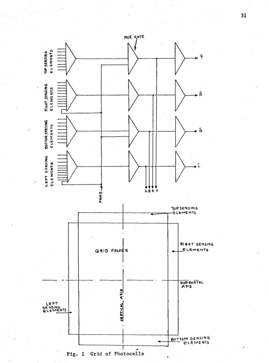
1. Grid of Photocells. 31
2. Hazard from Complementary Commands. 32
3. Representation of a Sequential Machine. 33
4. State Device. 34
5. Flow chart for Phase 2 Operation. 35
6 . Elements Used in Logic Drawings. 36
7. Realization of c^s and r^s. 37
8 . Phase 2 - Input Selector. 38
9. Phase 2 - Circuitry //l. 39
10. Phase 2 - Circuitry #2. 40
11. Phase 2 - Circuitry if3. 41
12. Phase 2 - Circuitry #4. 42
13. Phase 1 - Network #1. 43
14. Phase 1 - Network #2. 44
15. Phase 1 - Network #3. 45
16. Phase 1 - Network #4. 46
17. Phase 1 - Network if5 . 47
18. Phase 1 - Network if6 . 48
19. Phase 1 - Network #7. 49
20. Phase 1 - Network if8 . 50
21. Phase 1 - Network if9. 51
22. Phase 1 - Network #10. 52
23. Phase 1 - Network #11. 53
24. General System Flow Chart for Simulation. 54
CHAPTER I
INTRODUCTION •
An analogue - digital system for the recognition of hand printed
capital block letters and numerals projected on a grid of photo cells
was proposed by B.R. Dydyk^ at the Electrical Engineering Department of
the University of Windsor. As further research proceeded on this, it
was decided to develop the peripheral equipment of the system. The
analogue portion of the system required letters of uniform size
occupying as much of the grid as possible. This thesis presents the
logic design of a centering device whose objectives are:
(1) to mak e a character projected on the array of photo cells
(figure 1) lie symmetrically with respect to the horizontal
and vertical axes and
(2) to make it occupy m a x imum area of the grid.
A character is considered partially centered when it lies entirely
within the grid and on magnification simultaneously touches any two of
the parallel sides of the grid. A character is considered fully
centered wh e n it lies entirely w i t h i n ’the grid and on magnification
touches all the four sides of the grid or when a partially centered
character is shifted so as to lie symmetrically with respect to all the
sides of the grid. To achieve this the device has to know the previous
states of the character or in other words^it has to have a memory. The
signal that determines the state of the character is obtained from the
four sides of the array of diodes. It is called an input to the logic
network. Commands to magnify, contract or shift the character would
form the outputs of the network. The 'state' of the network corresponds
input and 'state' of the network. Such, a network is called a sequential
circuit. A character projected on the grid is shifted or contracted and
magnified once or a number of times before it gets centered partially
or fully by the sequential network. Partially centered characters
need only a further shifting which can be accomplished b y comparing the
rows or columns the character spans on either side of the reference axis.
The logic circuitry for this need only be of the combinatorial type
(no f e edback).
At present no information appears to be available on logic control
devices used to position a group of characters in pattern recognition
2 3
CHAPTER II
THE SYSTEM
2.1 Review of Sequential Circuits
Sequential circuits are usually classified as asynchronous or
4 4
fundamental mode circuits and synchronous or pulse m ode circuits.
Inputs which can remain in one state or another for an indefinite
length of time are termed level inputs. Asynchronous circuits have
level inputs. Inputs to synchronous circuits are gated by clock signals.
The outputs of sequential circuits can be of the pulse or fundamental
m o d e .
The function realized by a sequential circuit can be described by a
flowtable. The rows and columns of the flowtable cprrespond to the
internal states and primary input states. The entries of the flowtable
are the next internal state and output state. A total state is a
combination of an input state and an internal state. A decimal total
state number^ or simply a state number is defined as:
q-1 q+s-1
E
x • 2J + I
y * 2
(1)
j-0 3 p=q P
where x ., y = 0 or 1 , q and s are the number of variables in the
j P
input and internal states respectively ,
x , x _ x. represents an input state, and
q-1 q-2 0
^q+s 1 ^q+s-2 --- ^q r e Presents an internal state.
In asynchronous circuits, a total state is stable if the next state
entry is equal to the present internal state. When the circuit is in a
stable total state, the.internal state can change only after the input
state is changed.
is stable internally. If no more than one output change occurs for any
input change in an asynchronous circuit, it is called a normal sequential
circuit. A sequential circuit can be designed to operate meaningfully
either as a synchronous or an asynchronous device.
If (x^, X£, --- xr ) , are the inputs to a logic decision element and
the output is
Z = f (x^, X£, --- x ^ ) , a delay occurs between the time the inputs
are supplied and the time the output assumes the value designated by
the funcation Z = f (x^, --- x ^ ) . It is called an element delay. The
delay in the transmission of a signal along a line is called a line
delay. Line and element delays constitute stray delays. An inertial
delay element A is one that does not respond to input changes of
duration less than A.
In asynchronous circuits there are no clock signals to regulate
the circuit. Unger** has shown that in level input asynchronous
sequential circuits, if a closed loop -exists and if the system
variables are such that a signal m a y flow entirely around the loop, then
that loop must contain an amplifier. Such a loop is called a feedback
loop.
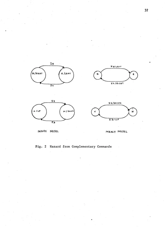
Sequential circuits can be represented in two ways-a Mealy model^
8
or a Moore model . In the Moore model the outputs are directly
dependent on the internal states whereas in the Mealy model the
outputs are dependent on the total state.
2.2 Outline of Proposed Method
5
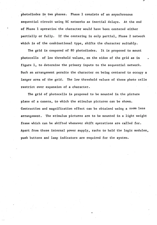
photodiodes in two phases. Phase 1 consists of an asynchronous
sequential circuit using RC networks as inertial delays. At the end
of Phase 1 operation the character would have been centered either
partially or fully. If the centering is only partial, Phase 2 network
which is of the combinational type, shifts the character suitably.
The grid is composed of 80 photodiodes. It is proposed to mount
photocells , of low threshold values, on the sides of the grid as in
figure 1 , to determine the primary inputs to the sequential network.
Such an arrangement permits the character on being centered to occupy a
larger area of the grid. The low threshold values of these photo cells
restrict over expansion of a character.
The grid of photocells is proposed to be mounted in the picture
plane of a camera, to which the stimulus pictures can be shown.
Contraction and magnification effect can be obtained using a zoom lens
arrangement. The stimulus pictures are to be mounted in a light weight
frame which can be shifted whenever shift operations are called for.
Apart from these internal power supply, racks to hold the logic modules,
LOGIC DESIGN OF THE CENTERING DEVICE
3.1 General Discussion
In the design of a sequential circuit the first decision to be
taken is the mode of operation of the circuit - synchronous or
asynchronous. Asynchronous circuits are faster because the system
operates at its own speed. Transient conditions during the change of
state variables cannot be ignored with asynchronous operation, and
several variables are allowed to change (referred to as a race) only
if the resulting state does not depend on the order of change of these
variables (referred to as n on critical r a c e ) . Though the problem of
races is not present wit h synchronous operation, stray delays in
combinational circuits and feedback lines can cause difficulties in
synchronising the next input and the next state to obtain the intended
behaviour of the system. In an asynchronous circuit if an input is
applied and held on the input lines, the machine will change state only
once, that is the next state will be a stable state under the input and
if.no critical race condition occur, the sequential circuit will remain
stable until a new input is applied. In an asynchronous circuit, to
change from the present to the next state, a sequence of internal
variable changes m ay be required and the time between input changes
must be sufficient to allow for the longest possible sequence.
5 9
Liu and Friedman have shown that normal fundamental mode
circuits can be realized such that in a transition from the present to
the next state, all internal state variables that need to be changed
can be allowed to change simultaneously without the hazard of critical
smallest possible number of amplifiers in the feedback loops. On this
basis, the sequential network is designed to operate in the fundamental
m o d e .
The primary inputs to the circuit will be taken from the four sides
of the grid. So sixteen input combinations are possible. The bits in
the input combination from left to right represent inputs from top,
right, b ottom and left sides of the grid. The inputs are coded as
follows: T R B L
11
0 0 0 0
12
0
0
0
1
13 0 0 1 0
14 0 0 1 1
15 0 1 0 0
16 0 1 0 1
17 0 1 1 0
18 0 1 1 1
19 1 0 0 0
110 1 0 0 1
111
1 0
1 0
112 1 0 1 1
113 1 1 0 0
114 1 1 0 1
115 1 1 1 0
116 1 1 1 1
T h u s input 18 means that the image touches the right, bottom and left
center a character on the grid:
(a) contraction
(b) magnification
(c) shift.
Under the shift operation the character is moved up or down or right or
left. The extent of shift is either full or one half the grid cell in
the direction of shift. Thus the output command 'full down' will shift
the whole character down by one grid cell. The command 'half right'
will shift the character right by one half grid cell. It becomes
necessary to shift by half grid cells, whe n the character spans an
odd number of rows or columns on the grid. The contraction and
magnification have to be uniform and their extent restricted to one half
of a grid cell. Distinct command signals are required to indicate that
the character is centered along the horizontal, vertical or both the
axes. If the character is touching the top, right and left sides of
the grid, it has to be moved down and contracted. So commands such as
'contract d o w n ' , 'contract up' etc. are required. In all seventeen
operations (indicated in Table I along with their binary and decimal
codes) are required. These comprise the output states of the sequential
network.
3.2 Flowtable
Table II indicates the initial flowtable for the asynchronous
machine. Table III summarizes all the states involved in the initial
flowtable. There are sixteen initial states. States JA, JB, JC, JD,
KA, KB, KC and KD are introduced to prevent the hazard of the machine
wi t h states B, E and C, H (see figure 2).
Stable internal states in the flowtable are distinguished by
underlining them. The decimal numbers besides the stable entries are
the desired outputs for the corresponding total states.
Before the internal states of the sequential machine are coded, it
is helpful to minimize the number of internal s t a t e s ^ . On the flowtable,
this operation corresponds to minimizing the number of rows. In a
Mealy type machine two or more rows can be merged if for each input
state these rows do not have conflicting entries. An entry which
appears in any one of the rows will appear in the composite row.
Underlined entries in any one of the merged rows will be underlined in
the composite row. In Moore model machines as the output is dependent
only on the internal state, two rows can be considered for merging if and
only if their outputs are the same. It is proposed to model the
sequential machine as a Mealy type for two reasons:
(1) It permits maximum row merger and hence minimum number of
internal states.
(2) The assignment technique developed by Friedman is particularly
suited to Mealy type machines.
The following rows can be merged together:
Rows Merged Composite Row Designator
AA, AB, AC, AD A
DA, D B , D C , D D , DE,
DF, DG, DH, DI, DJ, D K D
JA, JB, JC, JD J
KA, KB, KC, KD K
The condensed flovrtable appears as Table IV.
state and output state are considered equivalent unless there exists
some sequence of input states which m ay start from either of the two
underlined entries and give corresponding output sequences which differ
from one another. It is seen that there are no equivalent states in
the condensed flowtable. In the discussion that follows, the word
flowtable is to be taken to mean the condensed flowtable.
3.3 State Assignment
The eight rows of the flowtable indicate the need for binary 3-tuples,
y 2 y^ to code the internal states. If the assignment is made such
that any transition from one state to another changes only one y^
variable, no races occur. A binary three tuple can have only 3
adjacent three tuples. It is seen from the flow table that a
transition from state B can lead to states A, C, D, J or H depending
on the input. It is only possible to assign to any three of these,
states adjacent to B. Hence there is a necessity to employ
non-critical races. An initial assignment is made as follows. As many of
the next internal states as possible are made adjacent to the present
states.
A
0
0
0
B
0
0
1
C 0 1 0
D 1 0 0
E 1 1 0
H 1 1 1
J 0 1 1
1 1
Each column of the flowtable is examined separately for the nature of
transitions involved. If noncritical races are to be set up, it is done
by relaxing the excited state variables one by one from right to left
changing only one y^ variable at a time. This procedure is adopted to
avoid repetition of states unnecessarily and to be consistent.
Column 1
The transition paths are ;
Initial State Transition Path Final State
A 000 A
B 001 -> 000 A
C 010 -> 000 A
D 100 -> 000 A
E 110 -> 100 -> 000 A
* H 111 -> 110 -> 100 -> 000 A
Whatever be the intermediate states, the final state of 000 is always
reached and so no hazards are involved.
Column 2
The transitions involved are J
Initial State Transition Path Final State
A 000 -*-001 B
B 001 B
C 010 -> 011 ->001 B
D 100 -> 101 -> 001 B
E 110 -> 111 ->101 K
H 111 -> 101 -> 001 B
J 0 1 1 J
Critical races are observed in paths starting from C, D, E and H and
to avoid them the state assignment has to be augmented with additional
variables. The m i n imum number of additional variables required, can be
4 estimated using a method due to Liu .
A transition path can be represented using decimal total state numbers.
The decimal total state numbers are found (using expression 1) as
follows:
Total State State Number
E 12 1x 2 6+ 1x 2 5+ 0x 24+ 0x 2 3+ 0x 2 2+ 0x 2 1+ 1x 2° - 97
K 12 1x2 6+Gx2 5+1x2 4+0x2 3+0x2 2+ 0 x 21+ l x 2 0 = 81
H 12 1x 2 6+ 1x 25+ 1x 24+ 0x 23+ 0x 22+ 0x 21+ 1x 2° = 113
Stable state numbers in the transition path, are circled. The primary
input responsible for the transition is written over the first arrow.
The path from E to K in Column 2 would look like
12 ^
97 -► 113 @ .
A state number is said to repeat impermissibly 3 if
(1) an intermediate state number in a path is repeated in another
path wit h different following state numbers
(2 ) an initial or terminal state number of a path is repeated as
intermediate state numbers of other paths.
The transition paths in Column 2 using state numbers are
for starting states B, J and K wherein the final states are the
Two theorems due to Liu are given below without proof.
Theorem 1. In the transition of a flowtable if there is only one
state number S that repeats impermissibly and it
repeats exactly q > 1 times, then the necessary and
sufficient number of additional variables is given by
an integer that is the lowest to satisfy the inequality
m > l og2q.
Theorem 2. If more than one state number repeats impermissibly and
if the set of paths in which these state numbers repeat
are disjoint then the additional variables required is
the lowest to satisfy the inequality
m > log- (max (q.)) i
where state repeats q^ times, S 2 q 2 times and so on.
I n t h e a b o v e c a s e s , if a n i n i t i a l o r t e r m i n a l s t a t e n u m b e r is
repeating impermissibly, then the number of additional variables required
is m + 1. The intermediate state numbers of paths that have states
impermissibly repeating can be increased by the introduction of additional
u
in Column 2 repeat once impermissibly. State number 113 is also an
initial state number of path
12
113 + 81 ^ 17 .
12
If transition 97 •+• 113 -*■ 81 did not exist, one additional state
variable would have sufficed and the transition path would be set up as
f o l l o w s .
^ 2 4 1 -*• 209 ■* 145 - j
1 1 3 --- - 81 -- -► 17
The dotted arrows indicate the old transition path and solid arrows
indicate the new transition path. The number 128 (the new variable
is y j wi t h a weight of 2^ by expression 1) is added to every state
number of the path with impermissibly repeating state numbers. The
resulting sequence is made the path that leads from the initial to the
final state. The various transitions become
12 ® - >
33 -»• 161 -»■ 177 -> 145 -► QL5
12 /
65 + 193 -*• 209
X2 /
113 241
12 ^
97 -*» 113 + (8 l)
, and ( Q )
As state number 113 still repeats impermissibly, the addition of another
variable becomes necessary.
^ 3 5 3 -*■ 369 -> 337 ^
1 5
Firm arrows above, indicate the path, free of critical races.
For Column 2 it is therefore seen that two additional variables
are required to avoid critical races. Similar examination of other
columns show that no more than two additional variables are required to
avoid critical races and to effect the required transitions. Using
this assignment technique the sequential machine for the centering
device needs a sequence of up to four changes in state variables to
accomplish a change of state.
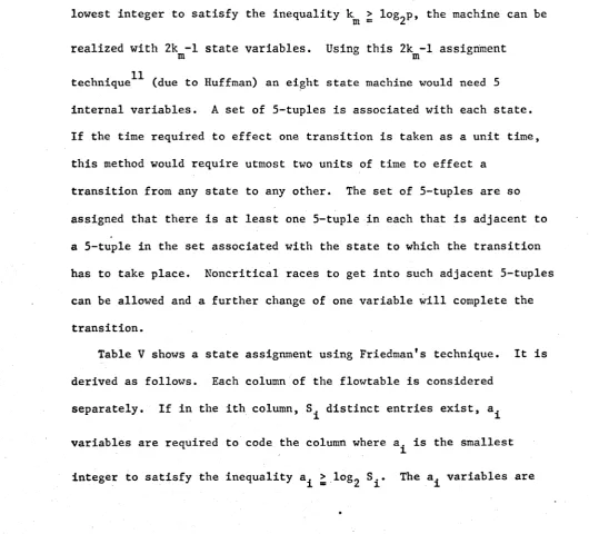
If p is the number of states of an asynchronous machine and k the
lowest integer to satisfy the inequality > log2P, the machine can be
realized w i t h 2km -l state variables. Using this 2km ~l assignment
t e c h n i q u e ^ (due to Huffman) an eight state machine would need 5
Internal variables. A set of 5-tuples is associated with each state.
If the time required to effect one transition is taken as a unit time,
this method would require utmost two units of time to effect a
transition from any state to any other. The set of 5-tuples are so
assigned that there is at least one 5-tuple in each that is adjacent to
a 5-tuple in the set associated wit h the state to which the transition
has to take place. Noncritical races to get into such adjacent 5-tuples
can be allowed and a further change of one variable will complete the
transition.
Table V shows a state assignment using Friedman's technique. It is
derived as follows. Each column of the flowtable is considered
separately. If in the ith column, S i distinct entries exist, a^
variables are required to code the column where a^ is the smallest
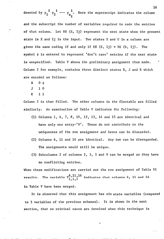
denoted by y^* --- y ^ . Here the superscript indicates the column
and the subscript the number of variables required to code the entries
of that column. Let NS (X, Ij) represent the next state when the present
state is X and Ij is the input. Two states X and U in a column are
given the same coding if and only if NS (X, Ij) = NS (U, I j ) . The
symbol <}> is entered to represent 'don't care' entries if the next state
is unspecified. Table V shows the preliminary assignment thus made.
Column 2 for example, contains three distinct states B, J and K which
are encoded as follows:
B 0 <j>
J 1 0
K 1 1
Column 2 is then filled. The other columns in the flowtable are filled
similarly. An examination of Table V indicates the following:
(1) Columns 1, 4, 7, 8 , 10, 12, 13, 14 and 15 are identical and
have only one entry-'O'. These do not contribute to the
uniqueness of the row assignment and hence can be discarded.
(2) Columns 6 , 11 and 16 are identical. Any two can be disregarded.
The assignments would still be unique.
(3) Subcolumns 2 of columns 2, 3, 5 and 9 can be merged as they have
no conflicting entries.
When these modifications are carried out the row assignment of Table VI
r e s u l t s . T h e v a r i a b l e I n d i c a t e s t h a t c o l u m n s 6, 1 1 a n d 16 X , X , 1
in Table V have been merged.
It is observed that this assignment has six state variables (compared
to 5 variables of the previous schemes). It is shown in the next
1 7
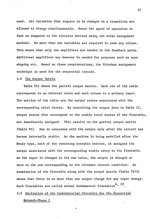
used. All variables that require to be changed in a transition are
allowed to change simultaneously. Hence the speed of operation is
fast as compared to the circuits derived using the other assignment
methods. No more than two variables are required to code any column.
This means that only two amplifiers are needed in the feedback paths.
Additional amplifiers may however be needed for purposes such as wave
shaping etc. Based on these considerations, the Friedman assignment
technique is used for the sequential circuit.
3.4 The Output Matrix
Table VII shows the partial output matrix. Each row of the table
corresponds to an internal state and each column to a primary input.
The entries of the table are the output states associated with the
corresponding total states. By consulting the output data in Table II,
output states that correspond to the stable total states of the flowtable,
are immediately assigned. This results in the partial output matrix
(Table VI). One is concerned with the output only after the circuit has.
become internally stable. As the machine is being modelled after the
Mealy type, each of the remaining unstable entries, is assigned the
output associated with the corresponding stable entry in the flowtable.
As the input is changed to its n ew value, the output is changed at
once to the one corresponding to the ultimate circuit condition. An
examination of the flowtable along with the output matrix (Table VIII)
shows that there is no more than one output change for any input change.
4 12
Such flowtables are called normal fundamental flowtables *
3.5 Derivation of the Combinatorial Circuitry for the Sequential
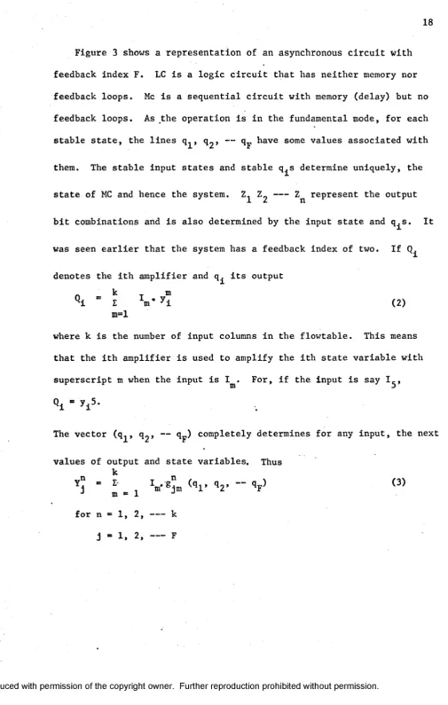
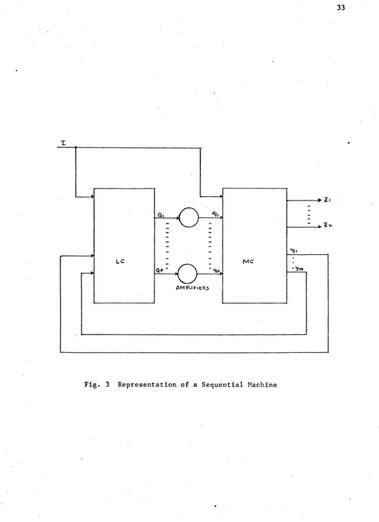
Figure 3 shows a representation of an asynchronous circuit with
feedback index F. LC is a logic circuit that has neither memory nor
feedback loops. Me is a sequential circuit with memory (delay) but no
feedback loops. As the operation is in the fundamental mode, for each
stable state, the lines q^, q 2 > — q^ have some values associated with
them. The stable input states and stable q^s determine uniquely, the
state of MC and hence the system. Z 2 --- Zr represent the output
bit combinations and is also determined by the input state and q ^ s * It
was seen earlier that the system has a feedback index of two. If
denotes the ith amplifier and q^ its output
‘k ’ E V y i (2)
k T m
I
m =l
where k is the number of input columns in the flowtable. This means
that the ith amplifier is used to amplify the ith state variable with
superscript m w he n the input is 1^. For, if the input is say 1^,
W -
.
The vector (q., q 0 , — q_) completely determines for any input, the next
X Z r
values of output and state variables. Thus
- * . v v < v v -- V (3)
J
m = 1
J
for n = 1 , 2 , --- k
1 is the number of bits in the output state •
Column I of the flowtable can be considered as a submachine MC .
m m
W he n the input is I , there are no critical races in MC . Whe n input
r m m
changes to I , MC is stable and so there are no critical races in MC.
° m ’ m
Variable y^1 changes only whe n the input is not 1^, that is it changes
only whe n not being used to prevent critical races.
To prevent combinational hazards involving q and I, an RC network
shown in figure 4 is used. This also serves as a state device. Since
an electromechanical device is employed to shift, magnify or contract
the character, the time constant of the state device must be slightly
greater than the time required for the electromechanical device to
complete a command such as contract-right.
Expressions for the feedback and state variables are derived as
follows.
From expression 2
Q x - I1+I4+I7+I8+I10+I12+I13+I14+I15
+12 y*+I3 y^+19 y^ + (16+111+116) y j * ^ 16
(5)
Q 2 - (I2+I3+I5+I9) y ^ , 5 , 9 ,
9
Expression for Y^ is derived as follows:
Q
Y^ is '1' if and only if the next state happens to be C, J or K.
20
The next state can be C if the input is 13. All these inputs are
considered one by one.
2
If the input is 12, ^1 " y l
Q = y 2 ’3 ’5 ’9 .
v2
y2,2,2,2
2
The next state can be J or K only if y^ = 1 »
9 3
Hence if 12 q^ is true Y^ is true. If the input is 13, = y^
3
and the next state is J or K if and only if y^ = 1. The next state is C
3 9
if y^ = 0. So Y^ is true whenever 13 is true. Similarly for the
inputs 15 and 19, the terms 15 and 19 q^ are to be included.
9 9
Hence the expression for Y^ becomes Y^ * 13+12 q^+I5 q^+19 q^. (7)
Expressions for other state variables are derived in a similar manner
and are given below.
Y^ « 15 q 1+ 12 q^ q 2 + 13 q 1 q^ + 15 q ^ + 19 q x q 2 (8)
Y 3 - 1 9 + 12 q ± + 13 qx + 15 q;L (9)
y 6,ll,16 = n + I6 + m + I16 ^ (10)
Y 3 = 12 + 13 q x + 15 q x + 19 q ± (11)
' X ’X m ' 15
q_i
+ 19 + 12 q l q 2 + 13 q l q 2+ 15 q x q 2 + 19 q x q 2 Q 2 )
There are five bits in the output code viz, Z^ Z 2 Z^ Z^, Z,.. Expression
21
• 1 if the Input is 12 and y Z ~ 10 i , e ’ if
— 3 2 3 5 9
12 q^ is true Z^ is true. If the input is 13 and = ^
Z^ is 'I*. Hence is true if q 2 Is true. If the input is
15 or 19 and q^ q 2 is true, Z^ is ’l 1. If the input is 1 ^ or 1^^ or 1^
and * 1 or 0 , is true. i.e. Z^ is true if 111 or 16 or 116
»
is true. Hence the expression for Z^ is
Z x = 16 + 111 +116 + 12 q x ^ + 13 qx q 2 + 15 q 3 q 2 + 19 q ±q 2 (13)
Expressions for the other output bits are derived in a similar manner
and are given below.
Z2
= 12 q;L q 2+I5 q x q"2+I9 ^1^ 2+14+17+18+110+112+113+114+115
(14)
Z3 = I3(q1 q 2+q’1 )+I5 q'j+Ig ^ + 1 4 + 1 7 + 1 8 + 1 1 0 + 1 1 3 + 1 1 4 + 1 1 5 (15)
Z4 = I2(q'1+ q 1 q^)+I3 qj+1.5 q^+116 q^+19 q^+Ill ^ + 1 6 + 1 1 0 + 1 1 2 + 1 1 3 + 1 1 4 (16)
Z 5 = I2(q1+ q 1q 2)+13(q1+ q 1q 2)+l6 q.j+111 q ^ I l + 1 4 + 1 7 + 1 8 + 1 1 2 + 1 1 6 (17)
Expressions 13 to 17 on simplification yield the following
Z1 « TBL q1q 2+RBL q ^ + T R L q ^q2+TRBL+TRB q ^ q 2+TRBL+TRBL (18)
CM
tsl = RL q ^q2+TB q^q2+TBL+RBL+TRB+RL q^q2+TRL (19)
Z 3 = TB q^+TB q 2+TB q^+RL q^+TRB+TBL+TRL+TBL (20)
Z4 = BL q 2+RB q ^ B L q-j+TR q^+TRB+TRL+TL q +TRBL q ^ (2 1 )
Z 5 = TR
1 *
22
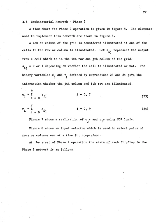
3.6 Combinatorial Network - Phase 2
A flow chart for Phase 2 operation is given in figure 5. The elements
used to implement this network are shown in figure 6 .
A row or column of the grid is considered illuminated if one of the
cells in the row or column is illuminated. Let represent the output
from a cell which is in the ith row and jth column of the grid.
s ^ = 0 or 1 depending on whether the cell is illuminated or not. The
binary variables c^ and r_^ defined by expressions 23 and 24 give the
information whether the jth column and ith row are illuminated.
cj ’ I . o 3 ’ ° ’ 7 (23)
7
r . = E s.. i ■ 0, 9 (24)
~ j - 0
Figure 7 shows a realization of c^s and r^s using N OR logic.
Figure 8 shows an input selector which is used to select pairs of
rows or columns one at a time for comparison.
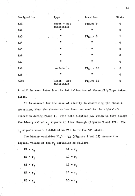
At the start of Phase 2 operation the state of each flipflop in the
2 3
Designation Type Location State
FA1 Reset - set Figure 9 0
(bistable)
FA2 " " 0
FA3 . " Figure 8 1
FA4 " " 0
FA5 " " 0
FA 6 " " 0
FA7 " " 0
FA 8 unistable Figure 10 0
FA9 " " 0
FA10 Reset - set Figure 11 0
(bistable)
It will be seen later how the initialisation of these flipflops takes
place.
It is assumed for the sake of clarity in describing the Phase 2
operation, that the character has been centered in the right-left
direction during Phase 1. This sets flipflop FA2 which in turn allows
the binary valued r^ signals to flow through (figures 9 and 12). The
c. signals remain inhibited as FA1 is in the 'O' state.
«l •
The binary variables H l ?‘— _ ^5 (figures 9 and 12) assume the
logical values of the r^ variables as follows.
HI * r LI *= r Q
o 9
H2 - r 1 L2 - rg
H3 = r 2 L3 » r ?
H4 = r 3 L4 r 6
The variables HI to H5 and LI to L5 represent the rows above and below
the horizontal axis of the grid respectively.
In the input selector FA3 is in the 1 state to start with. This
allows only HI and LI to pass through while H2 L2 etc. are inhibited.
Thus in figure 10, H and L assume the values of HI and LI. The H and L
signals are used in the comparison circuit (figure 11) to determine
the proper circuit output. Listed below are the different possible
outputs.
H L Required operation
0 0 Skip to next inner pair
0 1 Shift character (half-up)
1 0 Shift character (half-down)
1 1 Character centered
The skip to next inner pair for further comparison is effected as
follows. Since HL is 00, FA8 is set (figure 10). Shaper S emits a
pulse which sets FA9. FA9 returns to 'O' state after t seconds. The
neat negative pulse on the cc line resets FA3 and sets FA7. Therefore
the input selector changes H to H2 and L to L2. If HL is still ’00',
the pulse emerging from the delay line passes through to set FA9 again.
The delay A must be greater than the time constant t of FA9. During
A-t, H and L are allowed to take on the values corresponding to H2 and
L2. The pulse would be recycled as many times as required.
If the Phase 1 network has centered the character in the top-bottom
direction, c^s would be passed through to become H2, H3, H4, H5, L2, L3,
L4, and L5. HI and LI would be '00' (from figures 9 and 12) and the
2 5
Whe n the character is centered by the Phase 2 network, FA10 is
set which resets FA1 and FA2. When both FA1 and FA2 are in the 0
state,signal in the R line of figure 8 sets FA3 and resets F A 4 , FA5,
FA 6 and F A 7 . Also the Phase 1 network is returned to its starting
state D, by holding the primary input at 14 (figure 1 ). The output
associated with total state 14 D is inhibited. To process a new pattern
the 'START' button is to be pushed once.
3«.7 System Operation
The character is mounted on its frame and the initialise button is
pushed once. This sets FA 10 which initialises the Phase 1 and Phase 2
networks as described in section 3.6. Pressing the 'START' button
resets FA10 and allows the sequential circuit to read the primary inputs
and change state accordingly. If for any reason, the character on the
grid while being centered is lost, the centering process is stopped and
the networks are initialised. Pressing the START button would initiate
the centering process again. Lamp annunicators are used for displaying
messages, like 'character partially centered' etc.
3.8 Hardware Implementation
A scheme to realize the logic circuits is shown in Appendix A.
In arriving at this scheme, the following considerations have not been
taken into account
(1) loading rules for interconnecting the logic elements
(2) number of terminals available on each element.
On account of this, at the time of building the device proposed in
this thesis, it would be necessary to modify the implementation scheme.
The boolean expressions for the internal and output state variables
SIMULATION OF THE CENTERING DEVICE
The sequential network part of the logic device was simulated on
an IBM 1620 Model II computer. The general system flow chart for
simulation is given in figure 24. A listing of the program is attached
as Appendix C. The purpose of the simulation has been twofold.
(1) To check the behaviour of the sequential machine, for proper
operation, as envisaged in the flowtable.
(2) To serve as part of an overall simulation program of the entire
pattern recognition system proposed by Dydyk^. The program
solves Boolean expressions 5 to 17 for finding the next states and output
states. The program does not take into account the stray delays
involved in the logic elements. While all operations to shift the
character are performed automatically, magnification and contraction
have to be performed manually. The program prints out on the typewriter
the grid contents whenever such operations are called for. One has to
enter the data of the magnified or contracted character for the program
to carry on. This is a drawback of the simulation program.
Input to the program is from cards. A '1' is entered for a cell
that is illuminated and a '0* for one that is not illuminated. Figure 25
•shows the simulated grid. It has 32 rows and 28 columns. The simulated
grid is larger in size than the real grid to enable one to enter all the
data pertinent to the character.
Discussion of Results of Simulation:
Results of a typical simulation run is contained in Appendix D.
is touching the left side of the grid and hence the primary input is
'001' in decimal code. This corresponds to a primary input of 12 in
the flowtable. As the sequential network is in state 'D' to start
with, it changes to state B (coding is 000100). The output associated
with stable state B is 00011 (full-right). The character is shifted
two blocks to the right, whereupon the primary input becomes 15 and
the internal state changes to J(101101). The output associated with
total stable state 15, J is 'half left'. When the character is shifted
half block to the left the primary input and next state change to 16 and
D (000000). Wh e n the corresponding output command 'contract' is
performed, the internal state changes to A ( 0 0 0 0 1 0 ) . This requires the
character to be magnified and the grid contents as at this time of the
program are printed out row by row. On magnification, the primary
input changes back to 16 and the total state becomes 16, A. At this
time the pattern has been partially centered (a message to this effect
is printed out). Control is transferred to Phase 2 network, which
shifts the character such that it is symmetrical with respect to the
top and bottom sides of the grid. It is seen that the character occupies
13 rows on the simulated grid or about five and a half rows on the grid.
A character as this one, can get centered only if the output commands of
CONCLUSIONS
The use of photocells for the grid has certain drawbacks. Whe n a
character is projected on the grid, the cells near the projected
character would be activated to some extent and erroneous inputs are
likely to occur. Use of the additional pair of columns and rows on the
sides of the grid to supply the primary inputs, has permitted maximum
expansion of the character w ithin the grid. To minimize erroneous
inputs the operation of electromechanical drives to shift the pattern
should be as fast as possible. Simulation of the device shows that its
performance is satisfactory. In the absence of information regarding
other logic devices to position characters or patterns on grids such as
the one used here it is not possible to make any comparison. The
logic device proposed here is however considered novel for a pattern
recognition system such as the one proposed by D y d y k \ it can also be
made to handle a string of characters by modifying the grid size and
suitably changing the Phase 2 design.
B IB L IO G R A P H Y
1. Dydyk, R.B.; "A Proposal for Analogue cum Digital Character
Recognition", University of Windsor, Master's Thesis, 1965.
2. Rosenblatt, F . ; "Perceptron, A Perceiving and Recognizing Automaton",
Cornell Aeronautical Laboratory Report No. 85-640-1, 1957.
3. Block, H.D.; "The Perceptron: A Model for Brain Functioning"
Review of Modern Physics 34 (1962), pp 123-135.
4. McCluskey, E.J.; "Fundamental Mode and Pulse Mode Sequential Circuits" Digital Systems Laboratory, Princeton University, Technical Report No. 29, August 1962.
5. Liu, C.N.; "The State Variable Assignment Problem for Asynchronous
Sequential Switching Circuits", Digital Computer Laboratory, University of Illinois, Report No. 110, July 1961.
6 . Unger, S.H.; "A Study of Asynchronous Logical Feedback Networks",
Research Laboratory of Electronics, Massachusetts Institute of Technology, Quarterly Progress Report, April 1957.
7. Mealy, G.H.; "A Method for Synthesising Sequential Circuits",
BSTJ, Vol. 34, pp 1045-1079, September 1955.
8 . Moore, E.F.; "Gedanken-Experiments on Sequential Machines", in
Automata Studies, edited by C.E. Shannon and J. McCarthy,
Princeton University Press, Princeton, N ew Jersey, 1956, pp 129-153.
9. Friedman, A.D.; "Feedback in Asynchronous Sequential Circuits",
IEEE Conference Record on Switching Circuit Theory and Logical Design, October 1965.
10. Huffman, D.A.; "The Synthesis of Sequential Switching Circuits",
Sequential Machines: Selected papers, edited by Edward F. Moore,
pp 3-62, Addison-Wesley Publishing Company, Inc.
11. Huffman, D.A.; "A Study of the Memory Requirements of Sequential Switching Circuits", M.I.T., Research Laboratory of Electronics, Technical Report No. 293, March 1955.
•12. E i chelberger, E.B.; "Sequential Circuit Synthesis Using Hazards and Delays", Dissertation, Princeton University, March 1963.
3 1
V)
h-z
2Vi b
Z
Of t ID J
U1
■ r f f ' f L e * t
o
S 6 NSlNG ^ ^L£.^£NT3
G R I O PRC)P«:R
T O P S E N S I N 6
—ELEMENTS
R 1 6 H T S E N S IN G E L E M E N T S
HoRI 40N T A L
>V*tS
-15
*5/LEFT
T2-/RIOHT
x q /dow m
1 3 / u P
MOORE MODEL fviEALY M O D E L
3 3
X
L --- »
0
i
M
1
1
1
1
o
i
i
I
i
I
I
i *
i
LC M C
A M fU FIE R i
R
*o---
VvVVV^-E IN EooT
3 5
s t a r t
N O
^ATL£*Sf\ "ONE. OF t mSv
ySc. ORR £5 PONDIN'
Rows / c o l u m n s
l u m i
NVEOb-S H I F T A D V A N C E TC N E X T P A I R S E L E C T P R O P E R
I N P U T S C C O L U M N S / R O V N 5 P F O R C OIM PA - R I S O N N E T W O R K
P E T E R I V U N e O P E R A T I O N T O
(3E PERFORMED.
Fig.
NOR GATE
DELAY UNt
0
1 F L I P P L O P
S H A P E R
H e S T A T E D E V I C E
N O R GifltE W I T H /ADDED I N V E R T E R
3 7
o'* <*<*&:
t O T ' n v f l r
-F
i
g
.
8
P
h
a
s
e
2
-
I
n
p
u
t
S
e
l
e
c
t
o
P A I R F A2R 3 9 Co. H3 ci
> Hs
FA2R Hi FAIOS 2 |! 2 j i i 2* z s ■
Zl •
Hi •
£ 3 ■
'
2 S
-*■ FAIR
-► r FA 7 S
F At
I
-► F A l R
-*■ F/S25
F A 2
fn r3
<0 & r 2 O u>* uo V-3: O £ * ? uj 2 ct t~ Ui \J V- U/ 2 C*
111
HI
H 2
Rs
fis
--FA3R
Li
LS
*r <t
H
L
tr.1^5
F A 8 F
^ - .I5 FS
4 1
H A L F
\magT V-C:
HALF a E F T
HALF \up
^
HALF t>ovyN
I M I T I H L I S &
T W A 6 E Lo s t <
715
— H <C < IL U.
C5
£>1.3
ce,
c i —
4 5
<v,
y T
T
T
J l j , T L , Z j ZYi
Y P
T >3i,l
Y?
— A A A V -j—
T
r,
S ," > K
>1, 1,1
■ Y l
(0|
J
|<
?
£
< I-
^
t“
l°*
eO|
^»■
t<^
,,
11—
ts£|«
ft
->
h
|
«
i
«
a
(J
l(
-(
*t
l«
0|
J
T
•2=5
5 1
5 3
■*» f u l l r i g h t
■> Pu l l l e f t
Zl 22
2 3 2 4 2 5
F Ull yp
Z<
22 '
23
24
2 5
"*■ Fu l l d o w n
2 i -2i ‘ 23 ' ?4"
2 S ‘
FAIo.5 1||2LI t I
FW05
4M T O B E J-UOT G f i t A T e R T H A N C O N S T A T OF S T A T E P E V i C£ 4
Fig. 23 Phase 1 - Network #11
C O N I R e < T - R lO H T
C O N T R A C T - L . E F-T
CoNTRfltT-U p
C o N T R A C T
-t O W N
CONTRACT
STrtRT j
initialise
I
S T O P . FIND NEXT INTERNAL STftTg AND circuit
OUT PUT
P E R F O R M
OUTPUT oPERftT -ION.
P e r f o r m s h i f t
o p e r a t i o n o p p h a s eI
IF N £ E P £ D .
T3P JIM6 Row 3
£
ut
> 2
>
o
5
z U21l
(n inIU
Z
Ul 1
-<r> *
F
d. E
Ul
_j
S<>TTCM Ss'nsirJQ 3V\ s
TABLES
TABLE I
Output Codes
Decimal Coding 1 3 4 5
6
78
910
11
12
13 14 16 17 18 19 Operation MagnifyFull right
Full left
Full up
Full down
Half up
Ha l f down
Half right
Half left
Contract-right
Contract-left
Contract-up
Contract-down
Pattern centred in top-bottom direction
Pattern centred in all directions
Pattern centred in right-left direction