Power Usage Effectiveness analysis and
optimization in the INFN CNAF Tier-1 data center
infrastructure
Pier Paolo Ricci1,*, Andrea Mazza1, and Andrea De Zan2 1INFN CNAF, Viale Berti Pichat 6/2 40127 Bologna, Italy
2MCM Ingegneria S.R.L., Vicolo Monti 8 10095 Grugliasco (TO), Italy
Abstract. The accurate calculation of the power usage effectiveness (PUE) is the most important factor when trying to analyse the overall efficiency of the power consumption in a big data center. In the INFN CNAF Tier-1 a new monitoring infrastructure, also known as Building Management System (BMS), has been recently implemented using the Schneider StruxureWare™ Building Operation (SBO) software. During the design phase of this new BMS, a great attention was given to the possibility of collecting several detailed information about the electric absorption of specific devices and parts of the facility. Considering the annual trends and the demands for reducing the operating costs it became clear that some improvements were certainly needed in the very short time. For this reason, a hardware upgrade of the cooling chillers and related chilled water pumps distribution system was seriously considered using innovative cooling technology. We focused on chillers using the Danfoss Turbocor centrifugal compressors technology that uses magnetic levitation and an oil-free approach for obtaining the best efficiency. Subsequently, we studied a solution that could easily compensate the initial investment during the first years of usage (considering the Total Cost of Ownership of the project) and that will improve the overall PUE of our data center.
1 The INFN CNAF Tier-1 Facility resources
1.1 The actual infrastructures and resources
The INFN CNAF Tier-1 is located in the city centre of Bologna and it has become the Italian national data center for the INFN computing activities since 2005 [1]. Four major LHC experiments (ALICE, ATLAS, CMS and LHCb) use our site as a Tier-1 computing resource provider, in addition to roughly 25 other non-LHC collaborations including Astroparticle Physics (e.g. Kloe, AMS2, Argo, Auger, CTA, Magic, Pamela, Borexino, Darkside, Virgo, etc.). The computing and storage resources of our centre must be guaranteed to all these scientific community users with a 24/7 level of service support (which means a non-stop
service availability of 24h every day). The whole INFN CNAF Tier-1 center is currently located in a university complex building, which has shown to be a nonoptimal location.
During 2009 the upgrade of the Tier-1 resources filled up all the available space at our disposal and this corresponds to a total of 1950 m2 space occupation for two IT rooms (250
m2 + 350 m2) and four additional locations for the remaining main infrastructure facilities.
These four locations includes the transformers room, the UPS room (rotary UPS + one standard diesel generator used for backup purpose), the chillers room (including the water pumps and related piping system) and the power room with all the power switches and electrical measurement instruments and connections. In Figure 1 a simplified schema of the Tier-1 infrastructure resources is shown. As illustrated in the figure the main UPS power supply for the IT resources is guaranteed by two redundant Eurodiesel diesel rotary uninterruptible power supplies (DRUPS) with a nominal power of 1700 kVA each (equivalent to 1340 KW real power) connected to three electric transformers. The cooling power is provided by six Emerson free cooling chillers with 300 kW cooling capacity in a N+2 redundancy configuration. All the power distribution is carried out using two separated physical lines (identified by the RED and GREEN label), therefore it is technically possible to provide a full dual redundant power supply to all the IT equipment hosted in the Tier-1 data center. About the IT equipment cooling, our Tier-1 uses the Computer Room Air Handler (CRAH) approach, therefore cooling is accomplished by blowing air across an “air to water” heat exchanger. The cold water is provided by the six chillers that consume most of the energy required by the whole cooling process while the CRAHs (the APC InRow RPs which contain cooling coils filled with chilled water) modulate the fans speed to maintain the temperature set-point and provide the rooms humidity control.
Fig. 1. The INFN Tier-1 CNAF infrastructures system.
1.2 The INFN CNAF Tier-1 Building management system
The main task of a Building Management System (BMS) supervision system is monitoring and collecting all the necessary information and providing alarms in case of malfunctions or major failures of all the infrastructure facility elements. During 2016 a new BMS supervision
system was designed and implemented as part of a new revision project with the main purpose of renewing and improving the software and hardware supervision setup [2].
Currently the INFN Tier-1 infrastructure supervision system is based over two principal and distinct software packages:
• The Schneider StruxureWare™ Building Operation software (SBO) architecture: this is the principal BMS and alarm system with long-term trends archiving capability.
• The Schneider APC StruxureWare™ Data Center Expert (DCE): for fine monitoring, tuning and notification over APC InRow RPs and Metered Power Distribution Units (PDUs).
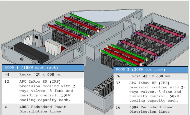
In addition to the major infrastructures elements described in Figure 1, the two principal IT computing rooms are carefully monitored by the supervision system. In Figure 2 a layout of the two rooms with the brief summary of all the relevant information is reported.
Fig. 2. The Tier-1 INFN CNAF two main computing rooms layout.
In particular, all areas of technical installations were evaluated for the analysis of the Power Usage Effectiveness (PUE) and partial PUE (pPUE) of the data center. The PUE is a measure of how efficiently a data center uses energy; specifically, how much energy is used by the computing equipment in contrast to cooling and other overhead. It can be calculated using the following formula:
(1)
=
(2)All areas for technical systems, described in the previous subsection, consisting of three transformers, two redundant 1340 kW DRUPS and six chillers of 300 kW cooling capacity were evaluated for the analysis of the Power Usage Effectiveness (PUE) and partial PUE (pPUE) using the new BMS supervision system.
The analysis of PUE and its subdivision into pPUE for cooling and power continuity shows that reducing at least one of these two elements is crucial for a consistent energy efficiency improvement. The reduction of our average annual PUE was also mandatory due to the recent increasing cost of the electrical energy. For this reason, a hardware upgrade of the cooling system and chilled water pumps distribution system has been seriously considered.
2 The Tier-1 cooling system upgrade preliminary study
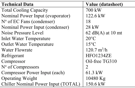
The design of a new project, including the hardware upgrade of the cooling chillers and the related chilled water pumps distribution, started in 2016 with the following collaboration of an external specialist engineering firm. The main idea behind the design of this new project was the utilization of chillers with an innovative cooling technology using magnetic bearing (magnetic levitation of the rotor) and an oil-free approach for obtaining the best efficiency in the HVAC (heat, ventilation and air conditioning) applications and consequently the lowest electricity consumption. Since there is no friction between moving parts the low power consumption and noise emission were the first advantages in addition to the high duration of mechanical parts. We therefore focused on chillers based on the Danfoss Turbocor® [3] centrifugal compressors technology. Chillers based on this compressor proved to be the most efficient on the market. As a first step, a comparison theoretical study between the actual chillers installations and the Turbocor® one has been carried out. A theoretical “custom” chiller was purposed based on actual vendor datasheets information. In Table 1 the technical specification of the “custom” chiller is reported.
Table 1. Custom chiller specification with an external T of 35oC
Technical Data Value (datasheet)
Total Cooling Capacity 700 kW Nominal Power Input (evaporator) 122.6 kW No of EC Fans (condenser) 18
Nominal Power Input (condenser) 28 kW
Noise Pressure Level 62 dB(A) at 10 mt Inlet Water Temperature 20°C
Outlet Water Temperature 15°C Water Flowrate 120.7 m3/h
Refrigerant HFO1234ZE
Compressor Oil-free TG310 No of Compressors 2
Compressor Power Input (each) 61.3 kW Operating Weight 10480 Kg Chiller Nominal Power Input (TOTAL) 150.6 kW
=
(2)All areas for technical systems, described in the previous subsection, consisting of three transformers, two redundant 1340 kW DRUPS and six chillers of 300 kW cooling capacity were evaluated for the analysis of the Power Usage Effectiveness (PUE) and partial PUE (pPUE) using the new BMS supervision system.
The analysis of PUE and its subdivision into pPUE for cooling and power continuity shows that reducing at least one of these two elements is crucial for a consistent energy efficiency improvement. The reduction of our average annual PUE was also mandatory due to the recent increasing cost of the electrical energy. For this reason, a hardware upgrade of the cooling system and chilled water pumps distribution system has been seriously considered.
2 The Tier-1 cooling system upgrade preliminary study
The design of a new project, including the hardware upgrade of the cooling chillers and the related chilled water pumps distribution, started in 2016 with the following collaboration of an external specialist engineering firm. The main idea behind the design of this new project was the utilization of chillers with an innovative cooling technology using magnetic bearing (magnetic levitation of the rotor) and an oil-free approach for obtaining the best efficiency in the HVAC (heat, ventilation and air conditioning) applications and consequently the lowest electricity consumption. Since there is no friction between moving parts the low power consumption and noise emission were the first advantages in addition to the high duration of mechanical parts. We therefore focused on chillers based on the Danfoss Turbocor® [3] centrifugal compressors technology. Chillers based on this compressor proved to be the most efficient on the market. As a first step, a comparison theoretical study between the actual chillers installations and the Turbocor® one has been carried out. A theoretical “custom” chiller was purposed based on actual vendor datasheets information. In Table 1 the technical specification of the “custom” chiller is reported.
Table 1. Custom chiller specification with an external T of 35oC
Technical Data Value (datasheet)
Total Cooling Capacity 700 kW Nominal Power Input (evaporator) 122.6 kW No of EC Fans (condenser) 18
Nominal Power Input (condenser) 28 kW
Noise Pressure Level 62 dB(A) at 10 mt Inlet Water Temperature 20°C
Outlet Water Temperature 15°C Water Flowrate 120.7 m3/h
Refrigerant HFO1234ZE
Compressor Oil-free TG310 No of Compressors 2
Compressor Power Input (each) 61.3 kW Operating Weight 10480 Kg Chiller Nominal Power Input (TOTAL) 150.6 kW
For the actual chillers statistics we decide to use the real data obtained from the BMS system in the last years for cooling requirement and the related electrical energy
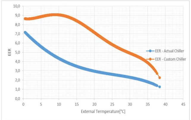
consumption. For the Custom chiller we estimated the energy consumption using the interpolated vendor datasheet tables with the 2012-2015 real trend of temperature in our city (Bologna) and a fixed cooling energy requirement of 700 kW. As a comparison parameter, we decide to use the Energy Efficient Ratio (EER). The EER parameter is very helpful for comparing chillers efficiency and it is usually the standard used in literature and in vendor data sheet. The EER is defined as the ratio between the Cooling Energy required in output and the electrical energy that is needed in input. We decide to calculate the EER value using a standard temperature of the cold water to the CRAH system of T = 15°C, a return water from CRAH of T = 20°C and, as outlined before, a fixed output Cooling Energy equivalent to 700 kW for the Custom chiller calculation.
In Figure 3 the plot of the two different EERs as a 4th grade polynomial interpolation trend line is reported. The plots shows that the energy efficiency of the Custom chiller is more than double to respect of the actual chiller.
Fig. 3. The EER plots of the actual and Custom chillers during the 2012-2015 period.
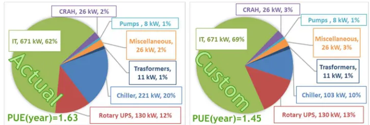
Fig. 4. The electrical power distribution of the actual and Custom chillers. An indication of the mean PUE value for both the scenarios is also reported.
3 Final design of the new cooling system
With the collaboration of the external specialist engineering firm, we continued looking into the preliminary study and we defined a project to be eventually realized in the future years, in anticipation of a consistent increase of the INFN CNAF Tier-1 IT load. The technical and economic analysis aimed to a gradual and progressive renewal of the actual cooling system with the integration of the new chillers. The temporal distribution of installations and any future disposal chillers was designed in order to minimize adverse effects on the activity of Tier-1, since the operation of the data center must be guaranteed 24/7. The main point of the study was the development of a solution that could easily compensate the initial investment during the first years of usage (considering the Total Cost of Ownership of the project). In addition, the usage of low-GWP (Global Warming Potential) refrigerants in the chillers, according to the dictates of the Green IT program, could help the administrative management of the infrastructure and reduce the risk of pollution in case of gas leaks.
The new cooling system project characteristics [4] were defined considering a maximum external temperature of T = 40 °C, as defined by the ASHRAE [5] Climatic Design Conditions, and can be summarized as follows:
• Total cooling power (Eurovent conditions [6]): 1400 kW.
• Single chiller nominal cooling power (Eurovent conditions): 700 kW.
• Total Number of chillers: 3 (in a “2 + 1” redundant configuration).
The idea was to allow a modular design and realization so that the following installation could be easily split into three independent phases with the last two that could be optional. The design phase with the external engineers confirmed the Danfoss Turbocor® magnetic bearing, oil-free centrifugal and variable speed compressors as main choice for the two principal chillers. The addition of one traditional screw compressors chiller is planned for redundancy purpose in a standard two (active chillers) and one (stand-by chiller) operation conditions. This configuration could also be easily separated into phases during installation. In agreement with our outside contractors, we concluded that, as cooling refrigerant, the HFO 1234ze gas is probably the most suitable despite the light flammability. Indeed, the TG Series of the Turbocor® compressor in addition to magnetic bearing introduces the HFO1234ze refrigerant, which has a very low Global Warming Potential (GWP < 1) and it is "F-Gas ready" (which means that is not considered as fluorinated greenhouse gases). This refrigerant is somewhat new, but the chiller producers expects a rapid transition to it in a broad range of applications, both industrial and commercial so this could be the future low-GWP standard for chillers comparable to our requirements.
Fig. 5. The physical location of the new chillers as defined in the final design.
In Figure 5 the solution for the physical location of the 3 chillers is reported. As depicted in the figure, chillers will be positioned on the top of the main building where the CNAF offices are hosted. This position will optimize the piping connection distance and it is also ideal for obtaining the best ventilation and heat exchange. The option of free-cooling could also be possible, improving the overall efficiency of the chillers. Suitable noise barriers should be installed in order to reduce the environmental impact for the surrounding households building in addition to an adiabatic system that helps efficiency when the external T would be high (external T > 25-30o C). Since the installation will proceed by stages during
the next years, the new chillers should be designed in order to work with the actual cooling system composed by the six Emerson free cooling chillers described in the previous sections. The actual chillers will be gradually put out of production as the new installation proceeds and can be used as redundancy options in case of major failure of the new system.
The three phases described in the project could be summarized as follows:
• PHASE 1: Installation of one Turbocor Chiller (700 kW) and optimization of the pumps circuit (secondary). The redundacy will be realized with the actual Emerson chillers (with the normal working condition OFF).
• PHASE 2: Installation of one additional Turbocor Chiller (700 kW) according to the expected increase in the Tier-1 IT load. The redundacy will continue to be realized with the actual Emerson chillers (with the normal working condition OFF).
The minimum savings expected from the PHASE 1 of this upgrade are roughly 130,000.00 € per year, which corresponds to a payback period of about 4-5 years considering a cost for the electrical power of 0.123 €/kWh + VAT. It is therefore clear that the realization of this upgrade could greatly increase the energy efficiency in our Tier-1 with a sustainable “green” solution that will easily cut maintenance costs.
4 Conclusions and future plans
This paper describes the latest developments for improving the INFN CNAF Tier-1 energy management efficiency. The energy efficiency in a modern data center could be evaluated using the Power Usage Effectiveness (PUE) and partial PUEs (pPUEs) as main indicators and these are one of the principal factors when considering the “value for money” of the global investment in the data center facility infrastructure. At the INFN CNAF Tier-1, using a new monitoring infrastructure as Building Management System (BMS), we were able to setup a more flexible and detailed data collection system. The collected data has clearly showed the pros and cons of our site and has indicated where exactly an improvement is technically possible. For this reason, a new project that aims to reduce the PUE by at least an estimated 10% using innovative cooling technology is currently under way. The introduction of modern and innovative cooling chillers with compressors using magnetic bearing and ecologic refrigerant will greatly reduce the total electrical power requirements of our Tier-1 according to the Green IT program. The future realization of this important infrastructure upgrade could greatly improve the Power Usage Effectiveness of our Tier-1 with a solution that will bring considerable benefits in the whole site functionality.
Acknowledgements: we would like to thank the whole staff of MCM Ingegneria S.R.L. for the valuable support in the development of the project.
References
1. G. Bortolotti et al., J. Phys. Conf. Series (JPCS) IOP Publishing 042016, The INFN Tier-1,396 (2012)
2. Ricci P et al., J. Phys. Conf. Series (JPCS) IOP Publishing 082005, Evolution of the Building Management System in the INFN CNAF Tier-1 data center facility,898 (2017) proceedings of the 2016 CHEP Conference
3. Info about Danfoss Turbocor® available online: https://www.danfoss.com/
4. Mazza A, CNAF Annual Report 2016, Tier-1 chiller upgrade plan 151-152 (2017) ISSN 2283-5490 available online: https://www.cnaf.infn.it/annual-report/
5. Info about ASHRAE (American Society of Heating, Refrigerating and Air-Conditioning Engineer) available online: https://www.ashrae.org/