Numerical Simulation of Crack Initiation and Growth in PBX High
Explosive Subject to Compression
Huang Xicheng1,*, Li Shangkun1, Wei Qiang1, Chen Gang1, Tian Rong2, Wang Lixiang2 1Institute of Systems Engineering, CAEP, 621900 Mianyang, China
2CAEP-SCNS, 10088 Beijing, China
Abstract. PBX solid high explosive exhibits brittle behaviour in uniaxial tension, quasi-brittle in uniaxial compression, and ductile when subject to high confining pressure. Tension cracking is the primary failure mode of PBX quasi-brittle solid, which is the main effect leading to overall failure of structural integrity. One characteristics of brittle or quasi-brittle solids, such as PBXs, is that when subject to overall compressive loading, the tensile cracks can still initiate inside the material due to existence of imperfection within the materials. In present study the extended finite element method is applied to analyze the cracking failure mechanism in the PBX 9502 platelike specimen with cavity subjected to overall compression. The nonlinear constitutive behaviours and failure of PBX under complex stress states were described by means of stress state dependent strength surface, non-associated flow rule and cohesive model the nonlinear behaviors of PBXs, including failure. Analysis indicates the tensile stress around the cavity arises in the specimen although loaded by overall compression, and this local tensile condition leads to cracking initiation. The comparison between simulation results and the experimental data published by LANL[Liu C, Thompson D G. Crack initiation and growth in PBX 9502 high explosive subject to compression. Journal of Applied Mechanics, 2014, 81(10):212-213] shows that they are in agreement with each other on some aspects of crack behaviours, including overall development of crack history and inflexion, crack initiation moment, crack initial speed, etc.
1 Introduction
Polymer-bonded explosives (PBXs), highly particle filled composite materials comprised of 90–95% by weight of powerful explosive crystals held together by a polymeric binder (5–10% by weight), have been used in a wide variety of applications ranging from rocket propellants to the main explosive charge in conventional munitions for civil and defence fields[1-4]. In recent decades, the safety and reliability of structures under low-speed impact have been highly valued by governments and engineering fields, and so the failure of PBX explosives has attached great attention by academic circles [5-12].
It is generally believed that the ignition mechanism of explosives under low velocity impact includes: elastic-plastic or visco-elastoplastic deformation, damage and failure, crack initiation and growth, plastic localization and plastic work conversion into heat and heat conduction [13]. It is found from the experimental observation that the plastic deformation and subsequent cracking problems of the energetic materials directly affect the evolution of the reaction (such as increasing the surface area will accelerate the combustion rate) and the reaction level [14]. The non-homogeneous damage within the material has great influence on the mechanical properties and sensitivities of explosives, and crack
propagation will directly affect structural integrity [15-16]. Therefore, it is necessary to understand the response of this material to mechanical stimulation, and then to provide theoretical supports for assessing the risk of crack occurrence and developing crack suppression technology.
analyse the crack initiation and failure of PBX 9502 plate with cavity against compression failure test [26].
2 Fundamentals of XFEM
XFEM is a new finite element method to solve the problem of fracture mechanics. It was first introduced by Belytschko and Black [38]. XFEM is an extension of the conventional finite element method based on the concept of partition of unity [39]. XFEM solved the problem of crack propagation in the finite element by using the idea of mesh separation independent. While retaining all the advantages of the traditional FEA, it is not necessary to mesh the existing cracks inside the structure. By far, XFEM is the most effective numerical method for solving the problem of discontinuities. It studies the problem within the framework of the standard finite element method, retaining all the advantages of the finite element method. This makes XFEM one of the main methods for simulating crack propagation. It represents the major advances in the numerical methods of computational mechanics field over the past decade. XFEM does not require aligning the meshes when dealing with cracks, and mesh refinement is not needed during crack growth, and high-precision numerical solutions can be obtained even on coarse meshes. These advantages of XFEM make this method very active in the field of computational mechanics for more than a decade [33, 35].
In the analysis of fracture problems, XFEM introduces enrichment functions, including: asymptotic functions near crack tip to characterize the stress singularity near crack tip; and discontinuity function to characterize displacement jump across crack surface. In this study, cohesive model [40] and phantom node method [41-42] are applied in the calculation of crack opening and propagation. In the framework of XFEM method, the traction-separation cohesive behaviour of material is introduced to simulate crack initiation and propagation. That is, XFEM-based cohesive method simulates the propagation of cracks within the material along any path, and mesh must not be updated to match the geometry of the discontinuity as crack progresses.
3 XFEM-based cohesive behaviour
The cohesive model belongs to the damage model. It was first introduced by Barenblatt [40] and used the traction-separation law (TSL) to simulate the decohesion of the atomic lattice, so as to avoid the singularity of the crack tip [43]. The cohesive model, combined with the finite element method, was first used in simulations of concrete, and was later introduced into simulations of metals, ceramics, composites and more. Cohesive interfaces or elements shall obey to the TSL, including viscoplasticity, viscoelasticity, rupture, fiber breakage, kinetic failure, and cyclic loading failure. The typical separation laws are Needleman's law [44], Hillerborg's law [45] and Bažant's law [46].
In present study, the crack propagation analysis is performed based on the XFEM-based cohesive segment
method, and the linear elastic TSL model, the damage initiation criterion and the damage evolution law. In the elastic TSL model, the initial linear elastic behaviour is assumed, followed by the onset and evolution of damage. The linear elastic behaviour is expressed as the linear relationship between the cohesive stress and the open displacement of the cracking element, namely:
=
t Kδ (1)
in which
T T
n s t n s t nn ss tt
[ , , ] ,t t t [ , , ] ,δ δ δ diag[K K K, , ]
= = =
t δ K
(2)
where t is the nominal traction stress vector, and tn , ts , tt
represent the normal and the two shear tractions, respectively, and the corresponding separations are denoted by δn , δs , δt. The normal and tangential
stiffness components will not be coupled: pure normal separation by itself does not give rise to cohesive forces in the shear directions, and pure shear slip with zero normal separation does not give rise to any cohesive forces in the normal direction. K is stiffness matrix, whose terms are calculated based on the elastic properties for an enriched element.
The maximum principal stress criterion is applied to model the cracking initiation, which can be represented as
0 max / max 1
f = 〈σ 〉 σ =
(3)
That is, damage is assumed to initiate when the maximum principal stress ratio reaches a value of one. Here, 0
max
σ represents the maximum allowable principal stress, in MPa. The symbol 〈〉 represents the Macaulay bracket with the usual interpretation.
A scalar damage variable, D∈[0,1], represents the averaged overall damage at the intersection between the crack surfaces and the edges of cracked elements. The variable monotonically evolves from 0 to 1 upon further loading after the initiation of damage. The damage evolution equation is described as energy dissipation according to
eqC
dD T= ( )d /δ δ G (4)
Here, σeqC is equivalent fracture energy release rate,
in J.m-2, which is described in Benzeggagh and Kenane
[47] by the following formula:
eqC IC ( IIC IC)[( II III) / ( I II III)]
G =G + G −G G +G G G+ +G η (5)
When material undergoes damage, the normal and shear stress components are affected by damage according to
n (1 ) n
t = −D T ,ts= −(1 D T) s,tt= −(1 D T) t
(6)
The crack will not occur when normal compression state is applied, i.e. tn=Tn. ComponentsTn, Ts, and Tt
the elastic traction-separation behaviour for the current separations without damage.
Under a combination of normal and shear separations across the interface, an effective separation is defined as following, so as to describe the comprehensive evolution of damage
2 2 2
m n s t
δ = 〈 〉 +δ δ +δ (7)
4 Description of plastic deformation of
PBX under complex stress states
According to the deformation characteristics of TATB-based explosives, such as the tension-compression asymmetry at quasi-static experiments at 50 °C [19], as shown in Fig. 1, the pressure-dependent yield surface, the non-associated flow law and the stress state dependent weighting function are utilized to describe the mechanical behaviour of the material under complex stress conditions.
The tensile and compressive test data are introduced into the model.
-3.5 -3.0 -2.5 -2.0 -1.5 -1.0 -0.5 0.0 0.5 -20
-15 -10 -5 0 5 10
str
es
s/M
P
a
Strain/% stress-T stress-C
Fig. 1. Quasi-static stress-strain curve of TATB explosive in tension and compression at 50 °C [19].
4.1 Yield surface
The PBX is described in the elastic deformation model using a linear elastic constitutive model, and the same modulus in tension and compression is assumed. In the plastic deformation stage, the confining pressure has an influence on its mechanical properties since PBX material is an internal friction material. Therefore, the first invariant of stress tensor (or hydrostatic pressure) should be introduced into the yield function. In this study the research findings of Lubliner et al. [48] are adopted, which are developed by Lee and Fenves [49] by consideration of the difference in strength between tensile and compressive stresses. The evolution of yield surface consists of two independent evolution parameters
p t
ε and εcp, as follows p
p p
max max c c
( , )
1 [ 3 ( ) ˆ ˆ ] ˆ ( ) 0 1
F
q αp β σ γ σ σ ε
α
=
− + 〈 〉− 〈− 〉 − =
−
σ ε
ε
(8)
Where σ is stress tensor, p p p T t c
[ , ]ε ε
=
ε ,p= −(1/ 3) :σ I
is hydrostatic pressure. q= (3 / 2) :S S is von Mises equivalent stress. α ,
β
and γ are dimensionless material parameters. The frictional angle is α =tan / 3ϕ , set as 20° according to ref. [50].max
ˆ
σ is maximum principal stress and (σb0/σc0) is strength ratio of biaxial
compression and uniaxial compression, set as 1.16 according to investigation into cohesive friction materials such as concrete . Kc=qTM/qCM is the ratio of
second invariants of stress tensor on tensile and compressive meridians, set as 2/3. p
t( )t
σ ε and p
c( )c
σ ε are cohesions obtained by experiments.
4.2 Flow potential function
Unlike metallic materials, the cohesive friction materials exhibit dilatancy characteristics and non-associated flow law should be used to calculate the plastic deformation [51]:
p = ∇ Φλ ( )=λ∂G( ) ∂
σ σ
ε σ
σ
(9)
2 2 t0
( tan ) tan
G= eσ ψ +q −p ψ (10)
where λ is non-negative plasticity consistency
parameter, the potential function G is assumed in the form of Drucker-Prager hyperbolic function. σt0 is
failure stress in uniaxial tension, in MPa. ψ is the dilatancy angle and e the eccentricity. The incremental constitutive relations can be established from yield surface and flow potential function as following [52] :
1
d F G : d
h
= − ∇ ⋅ ⊗ ⋅∇
σ C C C ε (11)
4.3 Plastic strain evolution
For the materials with tension-compression asymmetry, the plastic strain should be calculated by three principal strains weighted by distance function in stress space, i.e.
p p p T p p
t c ˆ ˆ ˆ
[ , ]ε ε ( , )
= = ⋅
ε h σ ε ε
(12)
where ˆ ˆ( , )p ( ) 0 0ˆ
ˆ 0 0 [1 ( )]
r
r
= − −
σ
h σ ε
σ
and
p p p p T 1 2 3
ˆ ˆ ˆ ˆ =[ , , ]
ε ε ε
ε . The plastic strain can be obtained by integration p p
t 0 ( )ˆmax
t
r
ε =
∫
σε . r( )σˆ is the distancefunction, weighting factor of triaxial stress defined as
def 3 3
1 1
ˆ ˆ ˆ
( ) i i / i | |i
r σ =
∑
=〈 〉σ∑
= σ(13)
here σˆi (i=1,2,…) are principal stresses. From (13),
ˆ ( )
weighting method, the material responses under complex stress states can be computed as long as the compressive and tensile curves are determined experimentally.
According to the test data of PBX [17, 50, 53], the material parameters could be obtained.
5 Computational model and analysis
In this study, the computational model is from the experimental configuration by Liu etc. [26]. The tested material is TATB-based explosive, the temperature is 50 °C, and the test is carried out by uniaxial compression. The loading rate is 1.27 mm.min-1. The
specimen geometry is a perforated rectangular plate, where a cavity with traction-free surface is located at the centre, shown in Fig. 2. The overall dimension of the plate is 76.2 mm in height, 38.1 mm in width, and 12.7 mm in thickness. The cavity at the centre of the plate has circular curved sections connected by four straight lines. The radii of curvature for the end-point and central curved sections are 6.35 mm and 1.905 mm, respectively. The length of the cavity is 19.05 mm.
In numerical simulation the plate is meshed by quadrangular plane stress elements, the element size is about 0.5mm. The maximum principal stress and fracture energy criteria are used.
Fig. 2. Specimen plate with cavity for fracture experiment on PBX 9502 subject to compression.
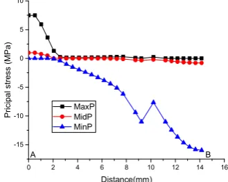
The results of XFEM analysis using code PANDA show that the stress and deformation field around the cavity of the plate subjected to overall compression are not uniform. The first principal stress at the upper and lower ends of the cavity is in tensile state, which is the largest on the inner wall. Fig. 3 shows the principal stress distribution along the inner wall of the cavity between point A to B. It can be seen that the first principal stress is the largest at point A and the third principal stress and shear stress are the maximum (absolute value) at point B. Therefore, the cracking mode and failure is firstly initiated on this point, and the direction of crack will be perpendicular to the direction of maximum principal stress. Secondly, the shear failure mode will initiate at point B [26].
Numerical simulation shows that non-uniform deformation and stress fields are generated near the holes
in the specimen under the effect of external compressive stress, resulting in stress concentration or high stress gradient. When local stress such as tensile stress reaches material failure stress, local cracking initiates. As the external load is further applied and deformation develops, the crack rapidly grows from the initiation site along the area of maximum principal stress, resulting in two macrocracks, as shown in Fig. 4.
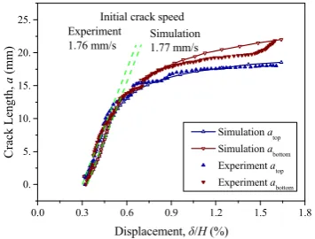
Figure 5 shows the numerical results of crack initiation moment, crack speed and crack propagation history in comparison with the experiment [26].
0 2 4 6 8 10 12 14 16
-15 -10 -5 0 5 10
B
P
rici
pa
l str
ess
(M
P
a)
Distance(mm) MaxP
MidP MinP
A
Fig. 3. Stress distribution on the inner wall of elliptical cavity in specimen.
Fig. 4. Crack initiation and growth of PBX 9502 platy specimen with cavity subjected to overall compression.
The numerical results show that the trend of crack growth is consistent with the experimental results, for example, the overall trend and inflection point of the upper and lower cracks. The cracking initiation moments for experiment and simulation are both at
/H 0.32%
δ = (about 0.2 min), and the experimental measurement of the initial crack speed is 1.76 mm.s-1,
the numerical simulation is 1.77 mm.s-1. This shows that
the method based on XFEM and cohesive model is feasible to simulate the initiation and propagation of crack Type I. Numerical simulation can give a good prediction on the overall development of crack initiation and growth. However, in some details, such as (1) numerical simulation results show that the crack propagation has a lag compared with the measured value, (2) In the late stage of crack development, there is a certain deviation between the simulated and measured crack locations. Possible reasons are:
tests, but it is very difficult to do in actual measurements, which may lead to differences on crack location, length.
(2) In the current calculation of XFEM, the simplified algorithm leads to crack crossing one element at one time step, and the crack speed in the element is infinitely fast. When the mesh is not fine enough, it will cause certain error on the crack growth.
(3) In the simulation of cracked interfaces, the damage of material leads to the softening and stiffness degradation of the material, and the numerical algorithm encounters the problem of convergence. To overcome this difficulty, the viscosity coefficient that characterizes the relaxation time of viscous system is introduced into the algorithm of cohesive constitutive model for viscosity regularization. This also leads to a small degree of slackening effect on material failure simulation.
(4) Because of the mesoscopic heterogeneity of PBX, the mechanical parameters have a certain degree of random distribution. In the process, the perimeter of the cavity is damaged to a certain degree, which may lead to local jumps on the crack propagation curve, e.g. the bottom curve. The numerical method of this study did not account for these effects.
0.0 0.3 0.6 0.9 1.2 1.5 1.8 0.
5. 10. 15. 20.
25. Initial crack speed Simulation 1.77 mm/s
C
rack
L
en
gt
h,
a
(m
m)
Displacement, δ/H (%)
Simulation atop
Simulation abottom
Experiment atop
Experiment abottom
Experiment 1.76 mm/s
Fig. 5. Crack initiation moment, initial crack speed and growth history curves.
6 Concluding Remarks
(1) Under the condition of overall compressive stress, non-uniform stress and deformation fields occur around the hole, resulting in local stress concentration. When the local tensile stress reaches the material failure strength, the cracking failure mode initiates at the local scale. With the load and deformation development, the cracking damage continues to evolve. While the critical value is reached, the crack further grows and propagates along the region of maximum principal stress, which eventually leads to the overall cracking of the material. This is the cracking mechanism of the hole-containing plate in compression. To reduce the concentration of tensile stress along the inner wall of the hole will help prevent cracking failure.
(2) The overall trend of crack propagation given by numerical simulation is in good agreement with the experimental results, including the overall trend and inflection point of cracking history, the cracking initiation time and the initial crack growth rate. It shows that the method based on XFEM and cohesive model is
feasible to simulate the initiation and propagation of crack of Type I, and numerical simulation can give a good prediction on the overall development such as crack initiation and growth.
(3) There is a certain degree of random distribution of PBX macroscopic mechanical parameters duo to the mesoscopic heterogeneity of PBX. Therefore, statistical test data are required to introduce the statistical properties of the material parameters into the numerical simulation.
This study was supported by the National Natural Science Foundation of China (Grant No. 11472257), the Science Challenge Project (No. JCKY2016212A502). The authors would like to thank Prof. Y. B. He and Prof. Z. M. Hao of CAEP for helpful discussions.
References
1. C.B. Skidmore, D.S. Phillips, P.W. Howe, J.T. Mang, J.A. Romero, In: Short J. M., Kennedy J. E. (Eds.), Proceedings of the 11th Detonation Symposium. Snowmass Village, Colorado (1998)
2. S. Ye, K. Tonokura, M. Koshi, Combustion & Flame,
132,1–2 (2003)
3. B.E. Clements, E.M.Mas, Modelling & Simulation in Materials Science & Engineering, 12, 12 (2004)
4. M.R. Baer, Thermochimica Acta, 384,1–2 (2002)
5. S.J.P Palmer, J.E. Field, J.M. Huntley, Proceedings Mathematical & Physical Sciences, 440, 1909 (1993) 6. M. Li, J. Zhang, C.Y. Xiong, J. Fang, J.M. Li, Y. Hao,
Optics and Lasers in Engineering, 43 (2005)
7. Liu Z W, Xie H M, Li K X, Chen P W, Huang F L. Fracture behavior of PBX simulation subject to combined thermal and mechanical loads.Polymer Testing, 28: 627– 635 (2009)
8. Chen P, Xie H, Huang F, Huang T, Ding Y. Deformation and failure of polymer bonded explosives under diametric compression test, Polymer Testing, 25(3): 333–341 (2006)
9. Chen P, Huang F, Ding Y. Microstructure, deformation and failure of polymer bonded explosives, Journal of Materials Science, 42(13): 5272–5280 (2007)
10. Pengwan Chen, Zhongbin Zhou, Shaopeng Ma, Qinwei Ma, Fenglei Huang. Measurement of dynamic fracture toughness and failure behavior for explosive mock materials, Front Mech Eng., 6(3): 292–295 (2011)
11. Li Jun-Ling, Fu Hua, Tan Duo-Wang, Lu Fang-Yun and Chen Rong. Fracture Behaviour Investigation into a Polymer-Bonded Explosive, Strain 48, 463–473 (2012) 12. Zubelewicz A, Thompson D G, Ostojastarzewski M, et al.
Fracture model for cemented aggregates, AIP Advances,
3(1):3275 (2013)
13. Danzhu Ma, Pengwan Chen, Qiang Zhou and Kaida Dai. Ignition criterion and safety prediction of explosives under low velocity impact. Journal of Applied Physics,
114(11):405-408 (2013)
14. Berghout H L, Son S F, Skidmore C B, et al. Combustion of damaged PBX 9501 explosive. Thermochimica Acta,
384(1-2):261-277 (2002)
16. Dienes J K, Zuo Q H, Kershner J D. Impact initiation of explosives and propellants via statistical crack mechanics. Journal of the Mechanics & Physics of Solids,
54(6):1237-1275 (2006)
17. Belmas R and Reynier P. Mechanical behavior of pressed explosives, International Symposium Energetic Materials Technology Florida, March 21-23, 1994:360-365 (1994) 18. Ellis K, Leppard C, Radesk H. Mechanical properties and
damage evaluation of a UK PBX. Journal of Materials Science, 40(23):6241-6248 (2005)
19. D.G. Thompson, G.T. Gray III, W.R. Blumenthal, C.M. Cady, W.J. Wright, B. Jacquez, LA-UR-02-6592 (2002) 20. D. Picart, J.L. Brigolle, Materials Science and
Engineering, A 527(2010)
21. Viet Dung Le, Michel Gratton, Michael Caliez, Arnaud Frachon, Didier Picart. Experimental mechanical characterization of plastic-bonded explosives. Journal of Materials Science, 45:5802–5813 (2010)
22. Picart D, Benelfellah A, Brigolle J L, Frachon A, Gratton M, Caliez M. Characterization and modeling of the anisotropic damage of a high-explosive composition. Engineering Fracture Mechanics, 131: 525–537 (2014) 23. Asay B W. Non-Shock Initiation of Explosives (Shock
Wave Science and Technology Reference Library, Vol. 5, Springer- Verlag, Berlin Heidelberg , 2010)
24. Trumel H, Lambert P, Belmas R. Mesoscopic investigations of the deformation and initiation mechanisms of a HMX-based pressed composition, in Proceedings of the 14th Detonation Symposium, Coeur d’Alene, USA (2010)
25. Gilles Pijaudier-Cabot, Zdenek Bittnar, Bruno Gerard. Mechanics of Quasi-Brittle Materials and Structures (HERMES Science Publications, Paris, 1999)
26. Liu C, Thompson D G. Crack Initiation and Growth in PBX 9502 High Explosive Subject to Compression. Journal of Applied Mechanics, 81(10):212-213 (2014) 27. Van de Steen B, Vervoort A, and Napier J A L. Observed
and simulated fracture pattern in diametrically loaded discs of rock material. International Journal of Fracture,
131:35–52 (2005)
28. Lemaitre J, Desmorat R. Engineering Damage Mechanics-Ductile, Creep, Fatigue and Brittle Failures (Springer-Verlag, Berlin, Heidelberg, 2005)
29. Xicheng Huang, Chengjun Chen, Gang Chen, Ming Liu. Analysis of deformation and failure of polymer-bonded explosives using coupled plastic damage model (Proceedings of the 20th International Conference on Composite Materials, Copenhagen, Denmark, 2015) 30. Ionita A, Clements B E, Zubelewicz A, et al. Direct
numerical simulations to investigate the mechanical response of energetic materials, Los Alamos National Laboratory, Los Alamos, NM, LA-UR-11-02598 (2011) 31. Toro S, Sánchez P J, Blanco P J, de Souza Neto E A,
Huespe A E, Feijóo R A. Multiscale formulation for material failure accounting for cohesive cracks at the macro and micro scales. International Journal of Plasticity, 76: 75-110 (2016)
32. Y.Q. Wu, F.L. Huang, Mechanics of Materials, 41,1 (2009)
33. Belytschko T, Black T. Elastic crack growth in finite elements with minimal remeshing. International Journal for Numerical Methods in Engineering, 45(5):601-620 (1999)
34. Zhuang Zuo. Extended Finite Element Method. Tsinghua University Press, 2012 (in Chinese)
35. Yu Tiantang. Extended Finite Element Method -Theory, Application and Programming. Science Press, 2014 (in Chinese)
36. Pommier S, Gravouil A, Combescure A, Nicolas Moës. Extended Finite Element Method for Crack Propagation. John Wiley & Sons, Inc. 173-226 (2013)
37. Tian Rong, Wen Longfei. Improved XFEM-An extra-dof free, well-conditioning, and interpolating XFEM. Computer Methods in Applied Mechanics and Engineering, 285:639-658 (2015)
38. Belytschko T, Black T. Elastic crack growth in finite elements with minimal remeshing. International Journal for Numerical Methods in Engineering, 45(5):601-620 (1999)
39. Melenk J M, Babuška I. The partition of unity finite element method: Basic theory and applications. Computer Methods in Applied Mechanics & Engineering, 139(1– 4):289-314 (1996)
40. Barenblatt G I. The Mathematical Theory of Equilibrium Cracks in Brittle Fracture. Advances in Applied Mechanics, 7:55-129 (1962)
41. Jeong Hoon Song, Areias P M A. and Belytschko T. A method for dynamic crack and shear band propagation with phantom nodes. International Journal for Numerical Methods in Engineering, 67(6):868-893 (2006)
42. Remmers J J C, Borst R D, Needleman A. Needleman, A.: The simulation of dynamic crack propagation using the cohesive segments method. J. Mech. Phys. Solids 56(1), 70-92 (2008)
43. Lawn B R. Fracture of Brittle Solids (Cambridge University Press, second edition, 1993)
44. Needleman A. An analysis of decohesion along an imperfect interface. International Journal of Fracture,
42(1):21-40 (1990)
45. Hillerborg A, Modéer M, Petersson P E. Analysis of crack formation and crack growth in concrete by means of fracture mechanics and finite elements. Cement & Concrete Research, 6(6):773-781 (2008)
46. Zdeněk P. Bažant. Concrete fracture models: testing and practice. Engineering Fracture Mechanics, 69(2):165-205 (2002)
47. Benzeggagh M L, Kenane M. Measurement of mixed-mode delamination fracture toughness of unidirectional glass/epoxy composites with mixed-mode bending apparatus. Composites Science & Technology, 56 (4):439-449 (1996)
48. Lubliner J, Oliver J, Oller S, et al. A plastic-damage model for concrete. International Journal of Solids & Structures, 25(3):299-326 (1989)
49. Lee J, Fenves G L. Plastic-Damage Model for Cyclic Loading of Concrete Structures. Journal of Engineering Mechanics, 124(8):892-900 (1998)
50. Gruau C, Picart D, Belmas R, et al. Ignition of a confined high explosive under low velocity impact. International Journal of Impact Engineering, 36(4):537-550 (2009) 51. Chen W F, Han D J. Plasticity for structural engineers
(Springer-Verlag, 1988)
52. EA de Souza Neto, D Perić, DRJ Owen. Computational methods for plasticity- theory and applications (New York, John Wiley & Sons, 2008)
53. Williamson D M, Palmer S J P, Proud W G. Fracture studies of PBX simulant materials, Shock Compression of Condensed Matter - 2005. American Institute of Physics,
![Fig. 1. Quasi-static stress-strain curve of TATB explosive in tension and compression at 50 °C [19].](https://thumb-us.123doks.com/thumbv2/123dok_us/8038300.1338128/3.595.90.246.352.479/quasi-static-stress-strain-curve-explosive-tension-compression.webp)