Deep Learning for Joint MIMO Detection and
Channel Decoding
Taotao Wang1,2,∗ , Lihao Zhang2and Soung Chang Liew2
1 College of Information Engineering, Shenzhen University; [email protected]
2 Department of Information Engineering, The Chinese University of Hong Kong; [email protected],
[email protected], [email protected]
* Correspondence: [email protected];
Abstract:We propose a deep-learning approach for the joint MIMO detection and channel decoding problem. Conventional MIMO receivers adopt a model-based approach for MIMO detection and channel decoding in linear or iterative manners. However, due to the complex MIMO signal model, the optimal solution to the joint MIMO detection and channel decoding problem (i.e., the maximum likelihood decoding of the transmitted codewords from the received MIMO signals) is computationally infeasible. As a practical measure, the current model-based MIMO receivers all use suboptimal MIMO decoding methods with affordable computational complexities. This work applies the latest advances in deep learning for the design of MIMO receivers. In particular, we leverage deep neural networks (DNN) with supervised training to solve the joint MIMO detection and channel decoding problem. We show that DNN can be trained to give much better decoding performance than conventional MIMO receivers do. Our simulations show that a DNN implementation consisting of seven hidden layers can outperform conventional model-based linear or iterative receivers. This performance improvement points to a new direction for future MIMO receiver design.
Keywords:deep learning; MIMO detection; channel decoding; deep neural network
1. Introduction
Multiple-antenna technology, also known as multiple-input multiple-output (MIMO), is one of the most important techniques for advanced wireless communications systems. It has already been incorporated into many wireless standards, e.g., 802.11n/ac [1] and LTE 4G [2]. It has also been shown theoretically that MIMO can increase spectrum efficiency linearly with the numbers of transmit and receive antennas [3]. Of much interest are low-complexity MIMO functional units that have good performance.
A MIMO transmitter transmits multiple data streams, one on each transmit antenna. A MIMO receiver receives a multiplexed copy of the multiple data streams plus noise on each receive antenna. A MIMO detector demultiplexes and decodes the multiplexed data on all the receive antennas into the originally transmitted multiple data streams plus noise and interference.
To achieve near-capacity performance, advanced channel coding schemes, such as LDPC and polar codes, have been suggested for 5G systems [4,5]. These channel codes protect the data streams against channel fading, interference, and noise. The output of a MIMO detector consists of a noisy version of the codeword transmitted by the transmitter. The function of channel decoding is to map the noisy codeword to the original information bits at the transmitter.
For optimal MIMO decoding, MIMO detection and channel decoding need to be performed in a joint manner. The conventional MIMO decoding schemes all use a model-based approach. However, due to the complex MIMO signal model, the optimal solution to the joint MIMO detection and channel decoding problem (i.e., the maximum likelihood decoding of the transmitted codewords from the received MIMO signals) is computationally infeasible.
As a practical measure, the current model-based MIMO receivers all use suboptimal MIMO decoding methods with affordable computational complexities. For example, instead of joint MIMO detection and channel decoding, [6–8] proposed to perform MIMO detection and channel decoding sequentially and separately, where MIMO detection is realized by linear equalizations with zero forcing (ZF) or minimum mean square error (MMSE) criteria. By contrast, [9–11] proposed to perform MIMO decoding and channel decoding iteratively with soft information exchanges between the two components. Thus, MIMO detection and channel decoding are performed in a joint manner. However, to contain complexity, the original MIMO signal model has been relaxed and replaced by an approximate model (i.e., it separately models the MIMO signal and the channel code). As a result, the solutions are still suboptimal. This leaves a gap for further performance improvement with better MIMO decoder designs.
To narrow the performance gap, this work applies the latest advances in deep learning for the design of MIMO receivers. In particular, we leverage deep neural networks (DNN) with supervised training to solve the joint MIMO detection and channel decoding problem. We show that DNN can be trained to give much better decoding performance than conventional MIMO receivers do. Our simulations show that a DNN implementation consisting of seven hidden layers can outperform conventional model-based linear or iterative receivers.
1.1. Related Work
Many MIMO detection schemes have been proposed [12]. Linear MIMO detection can first be used to cancel multiple-antenna interference with low complexities; after that channel decoding is performed [6–8]. In these schemes, linear MIMO detection and channel decoding operate in a sequential manner. Since linear MIMO detection introduces noise amplification and correlation, such sequential linear MIMO detection and channel decoding schemes typically result in large performance loss due to the mismatch between the noise models at the output of the MIMO detector and the input of the channel decoder.
To enhance the performance of MIMO detection, nonlinear MIMO detectors have also been proposed, e.g., MIMO detectors based on sphere decoding [13–15], semi-definite relaxation [16,17], and lattice reduction [15,18]. Unfortunately, these nonlinear MIMO detectors can only output hard estimates of channel symbols, making them incompatible with modern channel decoders that require soft input to achieve superior decoding performance.
Sphere decoding and list decoding algorithms were used for soft MIMO detection [9–11,19] that produces soft output. This soft information can then be fed to a channel decoding. Moreover, information exchange can be performed iteratively between soft MIMO detection and channel decoding to improve the overall performance of MIMO decoding. Although these iterative MIMO decoding schemes have better performance than the sequential schemes, their solutions are still approximate and suboptimal, due to the mismatch between the noise model of the soft output of the MIMO detector and the assumed noise model at the input of channel decoder. Furthermore, iterative information exchange introduces large decoding latencies.
Unlike the above model-based approaches, [20] proposed a deep learning approach for MIMO detection. Specifically, the method approximates MIMO detection using deep neural networks (DNN). The method progressively improves the approximation by adjusting the weights of a DNN based on a series of training MIMO signals. Compared with model-based MIMO detection, deep-learning MIMO detection achieves similar detection accuracies with faster detection speed. However, this deep-learning MIMO detection scheme can only perform hard MIMO detection and cannot be combined with a soft channel decoding scheme.
propagation decoding when the factor graph of the linear codes contains many samll loops. Work [25] investigated DNN-based joint equalization and channel decoding problem for non-MIMO systems. A survey on the applications of deep learning to wireless systems can be found in [26].
The remainder of this paper is organized as follows. Section II presents the system model of MIMO systems. Section III reviews the existing model-based MIMO receivers. Section IV presents our deep learning MIMO receiver. Section V provides the simulation results. Finally, Section V concludes the paper.
2. System Model
This section presents the system model of MIMO systems and the format of the received MIMO signals.
Consider a MIMO system where the transmitter is equipped withMTantennas and the receiver is equipped withMRantennas. The channel between each transmit-receive antenna pair is assumed to incur frequency-flat fading and the channel state remains constant within one transmitted packet. We assumeMT ≤MRandMTparallel data streams are transmitted, one on each transmit antenna.
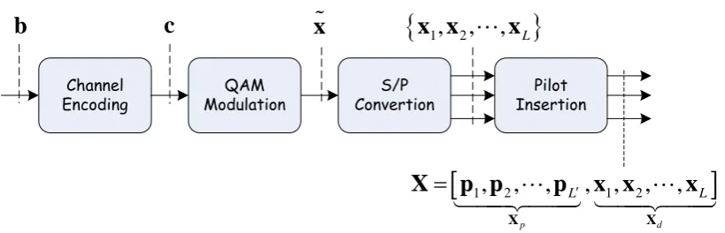
Figure 1 shows the block diagram of the MIMO transmitter. At the transmitter side, a vector ofKinformation bits,b = [b1,b2,· · ·,bK]T, is first channel-encoded into a codeword vector c = [c1,c2,· · ·,cN]T of length N = K/R, where Ris the code rate. The valid set of codewords is denoted by Cand thus c ∈ C. The coded bits in vectorcare modulated to a vector of complex data symbols,˜x= [x1,x2,· · ·,xN/B]T, whereBis the number of code bits per complex data symbol. The modulation constellation is scaled so that the modulated symbols in ˜xhave unit average power. Through serial-to-parallel conversion, the vector ˜xis partitioned into L =∆ N
(BMT)consecutive data vectors of length MT, {x1,x2,· · ·,xL}, i.e., we have ˜x = xT1,x2T,· · ·,xTL
T
. Then, L0 pilot vectors of length MT,{p1,p2,· · ·,pL0}, are prepended to the data vectors{x1,x2,· · ·,xL}to form anMT×(L0+L)signal matrixX=Xp,Xd
, whereXd= [∆ x1,x2,· · ·,xL]is theMT×Ldata matrix that contains the data vectors, andXp = [∆ p1,p2,· · ·,pL0]is theMT×L0 pilot matrix that contains the pilot vectors. We assumeL0 ≥ MT to facilitate the channel estimation [27]. The signal matrixX represents one transmitted packet. TheMTsymbols of thet-th column vector in the signal matrixX are simultaneous transmitted on theMTtransmit antennas in thet-th time slot.
At the receiver side, the received signals are written into an MR×(L0+L) matrix, Y =
[y1,y2,· · ·,yL0+L], where thet-th vectorytcontains the received signals on theMRreceive antennas in thet-th time slot. The received signal matrix can be written as
Y=
s
1 MTHX
+W (1)
where H is an MR×MT complex channel matrix with zero-mean and σ2-variance independent complex Gaussian entries, andWis theMR×(L0+L)additive white Gaussian noise (AWGN) matrix that has zero-mean and unit-variance independent complex Gaussian entries. We also divide the received signal matrix and the AWGN matrix into two subparts:Y=
Yp,Yd
,W=
Wp,Wd
, where Ypis theMR×L0matrix that contains the received signal vectors for the transmitted pilot vectors,Yd is theMR×Lmatrix that contains the received signal vector for the transmitted data vectors, andWp, Wd, are the matrices containing the noise components inYp,Yd, respectively. The aim of the MIMO receiver is to decode the transmitted information bits inbfrom the received signal matrixY.
Channel
Encoding ModulationQAM ConvertionS/P InsertionPilot
b
c
x
x x
1,
2,
,
x
L
1,
2,
,
,
1,
2,
,
p d
L L
X X
X
p p
p
x x
x
Figure 1.The block diagram for the MIMO transmitter.
3. Model-based MIMO Receivers
Traditional MIMO receivers have been extensively studied in the literature and implemented in real systems. This section gives a brief overview of these MIMO receivers.
A symbol-wise optimal MIMO receiver decodes each information bit,bk, from the received signal matrixYd by minimizing the symbol error probability or equivalently maximizing thea posteriori probability(APP):
ˆ
bk=arg max
bk p(bk|Yd,H,C) (2)
where ˆbk denotes the estimate of the information bit bk, andk ∈ {1, 2,· · ·,K}. The problem as expressed in (2) is in fact ajoint MIMO detection and channel decodingproblem, since data symbol detection and the channel decoding are implicitly performed in (2). We point out that joint MIMO detection and channel decoding as in (2) require the knowledge of the channel matrixH. In practice, the channel matrix is typically estimated from the received pilot signalsYp, e.g., the least square (LS)
estimate of the channel matrix is given by:Hˆ =√MTYpXHp
XpXHp
−1
[27]; then, the channel matrix
estimateHˆ is substituted back to (2) to replace the real channel matrixH.
Even with the above approximation which replacesH by H, the exact computation of APP,ˆ p bk
Yd,H,ˆ C
, is difficult and highly complex. The computation difficulty is due to: i) the correlation among the data symbols introduced by channel encoding; ii) the parallel signal interference caused by the MIMO channel. Therefore, suboptimal MIMO detection and channel decoding schemes with manageable implementation complexities are typically used in practice. We overview two suboptimal schemes in the following.
3.1. Linear MIMO Receivers
One suboptimal MIMO detection and channel decoding approach is to cancel the parallel signal interference with a linear MIMO detection first and then perform channel decoding next. We refer to this approach as linear MIMO receivers. For example, the zero-forcing (ZF) detection [6] removes the interference by
˜ Yd=
p
MT
ˆ
H ˆHH−1HˆHYd=Xd+W˜d (3)
whereY˜dis the post-cancellation signals andW˜d= √
MT HdHHd
−1
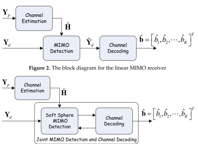
Wdis the post-cancellation noise. Since parallel signal interference is already removed in (3), the post-cancellation signals,Y˜d, can be fed to a traditional channel decoder to recover data symbols. Figure 2 shows the block diagram for this linear MIMO receiver.
Channel Estimation
p
Y
MIMO
Detection DecodingChannel
d
Y
ˆ
H
d
Y
ˆ
ˆ ˆ
1,
2,
,
ˆ
T
K
b b
b
b
Figure 2.The block diagram for the linear MIMO receiver
Channel Estimation
p
Y
Soft Sphere MIMO Detection
d
Y
ˆ
H
Channel Decoding
1 2
ˆ ˆ
ˆ
ˆ
,
,
,
TK
b b
b
b
Joint MIMO Detection and Channel Decoding
Figure 3.The block diagram for the iterative MIMO receiver.
3.2. Iterative MIMO Receivers
The second MIMO detection and channel decoding approach performs iterative soft-in soft-out MIMO detection and channel decoding. UsingH,ˆ Ydand the prior information about the data symbols, a soft MIMO detector computes the extrinsic information about the data symbols [9] and delivers the soft information to a soft channel decoder. The soft channel decoder then computes the new extrinsic information about the data symbols and send the computed new extrinsic information back to the soft MIMO detector for further iteration.
In the next round of iteration, the soft MIMO detector replaces the prior information about the data symbols with the information sent from the soft channel decoder and re-computes its extrinsic information about these data symbols again. Several rounds of such iterations are performed to ensure the convergence of the overall MIMO detection and channel decoding process. We refer to such iterative MIMO detection and channel decoding schemes as iterative MIMO receivers. It yields an approximate solution to the joint MIMO detection and channel decoding problem expressed in (2).
Figure 3 shows the block diagram for the iterative MIMO receiver. The soft MIMO detection often used is the sphere algorithm [11] and the soft channel decoding often used is the belief propagation algorithm. The complexity of the iterative MIMO receiver is much higher than that of the linear MIMO receiver. Although the iterative MIMO receiver has better performance than the linear MIMO receiver does, there is still a large performance gap with respect to the optimal MIMO receiver. Moreover, the iterative information exchange introduces large decoding latency.
4. Deep-Learning MIMO Receivers
We propose to employ deep neural networks (DNN) to solve the joint MIMO detection and channel decoding problem stated in (2) with the goal of improving performance. The DNNs are trained under the framework of supervised learning.
MIMO Transmitter Random Source Bits Generator Generating Training Data Channel Estimation AWGN Generator
i
b X di
i d Y ˆ H p Y ˆ H ˆi b ... ... ... . . . . . . . . . . . . ˆ H ˆ b
DNN Joint MIMO Detection and Channel
Decoding d Y Received Signals From MIMO Transmitter
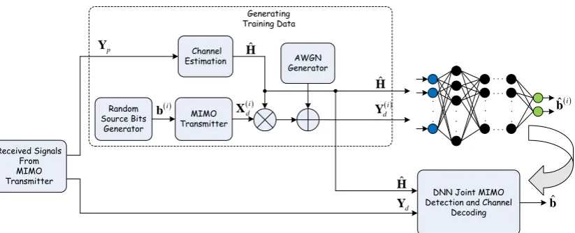
Figure 4.The block diagram for the iterative MIMO receiver.
The receiver generates the training data by calling a functional block that mimics the operation at the MIMO transmitter. Specifically, for training purposes, the receiver randomly generates many length-Kbinary vectors,b(i),i=1, 2,· · ·,Z. Each binary vectorb(i)is transformed into a data matrix X(di)using the functional block of the MIMO transmitter as described in Section II. Then, with the channel matrix estimateHˆ given by the channel estimator, the receiver generates a training signal by multiplyingHˆ withX(di)followed by adding AWGN:
Y(di)=p1/MTHXˆ
(i)
d +W
(i)
d
whereY(di)is thei-th training signal andW(di)is the corresponding generated AWGN. The training set is given byD Hˆ
=nY(di),b(i) Hˆ
oZ
i=1, whereY (i)
d is thei-th training signal andb(i)is the corresponding label forY(di). We emphasize that the training set is dependent on the channel matrix estimateH.ˆ
We use the generated training set to train a DNN,fθ(·), that approximates the solution to problem (2), whereθis the set containing all the weights of the edges in the DNN. When we feed the training
signalsnY(di)oZ
i=1to the inputs of the DNN, we also feed the channel matrix estimate ˆ
Hto the DNN (as illustrated in Figure 4). We optimize the DNN weights by miming the cross entropy loss function [28]:
L θ,D Hˆ
= 1 ZK
Z
∑
i=1 K
∑
k=1
h
bk(i)lnbˆk(i)+1−b(ki)ln1−ˆb(ki)i (4)
whereb(ki)∈ {0, 1}is thek-th target information bit of thei-th label vectorb(i), ˆb(ki)is the soft estimate ofb(ki) ∈ {0, 1}given by the DNN. The training algorithm used to minimize (4) for DNN is the so called stochastic gradient descent (SGD) algorithm [28]. After the training is finished, the weights of the DNN are fixed to ˆθand we can use the trained DNN fθˆ(·)to decode the received signals as
ˆb= fθˆ(Yd). We have the following remarks on this DNN for MIMO:
• The variables of interests to the DNN are the data symbols inX(di). The size of the variable space
is thus 2K, whereKis the length ofb(i)(Note that we have the one-to-one mapping:b(i)→X(di)). According to the results shown in [21], if the DNN can see all possible codewords, the decoding performance of the DNN is the best. Like the investigation in [21], we also adopt short codes and train the DNN with all different codewords.
requirements, such as voice transmissions; it is, however, suitable for data transmissions with relaxed latency requirements.
5. Simulation Results
In this section, we present simulation results for the evaluation of the proposed DNN MIMO receiver. The modulations used are BPSK and QPSK. The channel code used is the polar code [5] with code rate 1/2. We assume that that each packet consists ofK=16 bits in the simulations. The adoption of the short packet length is due to the exponential training complexity when DNN is used to perform channel decoding [21].1Packets of short length are of interest in some practical systems such as the internet of things (IoT). After channel encoding and modulation,K=16 information bits are transformed to 32 BPSK symbols or 16 QPSK symbols. Our simulations assume MIMO matrices of dimensionsMR×MT =2×2, 4×4 and 8×8.
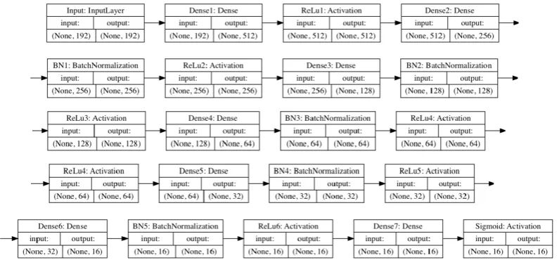
We implement a DNN consisting of one input layer, six hidden layers and one output layer using the deep-learning software toolkit of Keras. The nonlinear activation function at the neurons of the input layer and the hidden layers is the Rectified linear unit (ReLu) function [28]. The input layer is a densely-connected layer. Each hidden layer is a densely-connected layer with batch normalization (BN) operations before the operations by ReLu. The output layer is a densely-connected layer with the sigmoid activation functions. The architecture of the DNN is illustrated in Figure 5. We train our NN over several “epochs”. In each epoch, the gradient of the loss function is computed over the entire training set using Adam, a method for stochastic gradient descent optimization [29]. Our training set contains all different 2Kcodewords,Kis the length of information bits. Setting the number of learning epochs to 105, we train the DNN with datasets of different training SNRs (from 0 dB to 6 dB). After the training is finished, the trained DNN is used to decode the received MIMO signals.
Figure 5.The architecture of the adopted DNN consisting of six hidden layers with 512, 356, 128, 64, 32, and 16 neurons respectively.
For comparison, we treat the following two traditional MIMO receivers as our benchmarks: i) the linear MIMO receiver that employs ZF MIMO detection followed by the MAP polar decoding of [5], ii) the iterative MIMO receiver that iterates between the sphere MIMO detection of [11] and the MAP polar decoding of [5]. We investigate the performance of MIMO receivers with perfect knowledge as well as with imperfect knowledge of the channel matrix. For the latter, we assume LS estimation [27]
0 1 2 3 4 5 6 7 8 9 10
SNR
10-5 10-4 10-3 10-2 10-1 100
BER
2X2 Linear MIMO Rx 2X2 Iterative MIMO Rx 2X2 DNN MIMO Rx 4X4 Linear MIMO Rx 4X4 Iterative MIMO Rx 4X4 DNN MIMO Rx 8X8 Linear MIMO Rx 8X8 Iterative MIMO Rx 8X8 DNN MIMO Rx
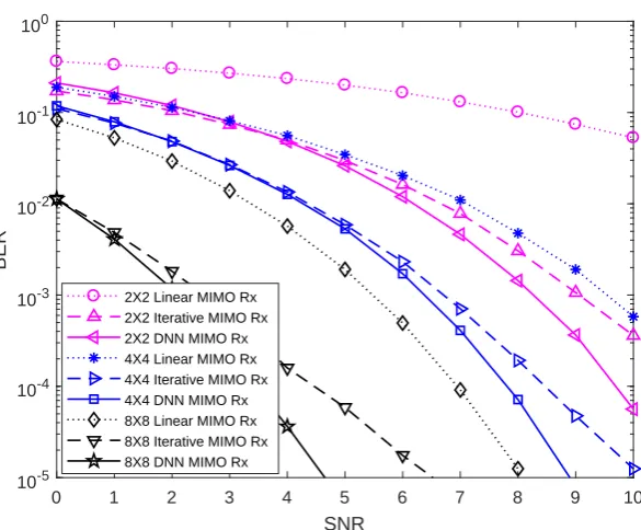
Figure 6.BER of the MIMO receivers with perfect knowledge of the MIMO channel matrix for BPSK.
is used to estimate the channel matrix. For a fixed SNR, we evaluate the average BER results of the MIMO receivers over 100 different MIMO channel realizations.
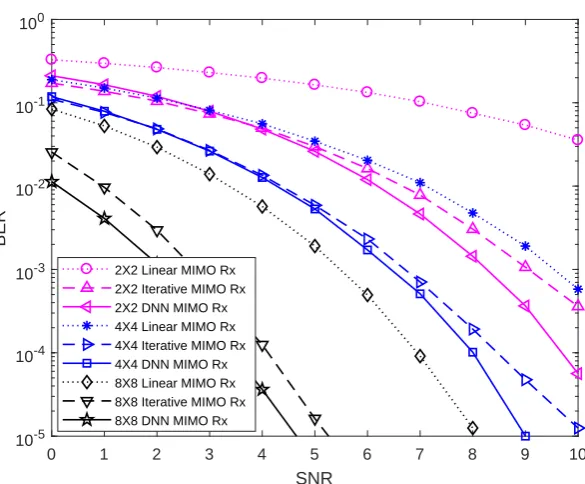
Figure 6 and Figure 7 show the BER of the MIMO receivers with perfect knowledge of the MIMO channel matrix for BPSK and QPSK, respectively. We can observe that our DNN MIMO receiver can indeed outperform the linear and iterative MIMO receivers in terms of BER. For example, the DNN MIMO receiver has around 1 dB and 3.5 dB SNR gain over the linear and iterative MIMO receivers, respectively, at the BER of 10−4for BPSK and 8×8 MIMO channels.
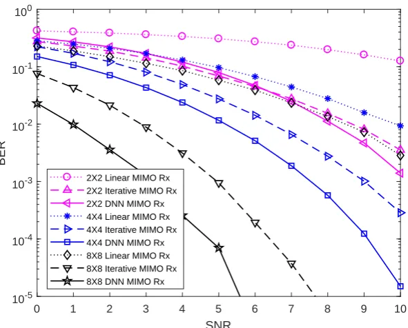
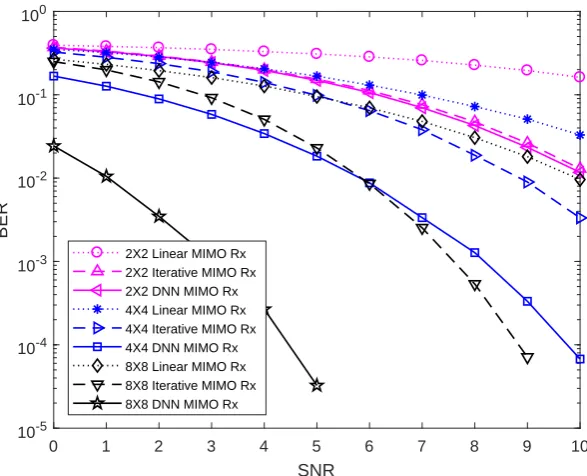
Figure 8 and Figure 9 show the BER of the MIMO receivers with imperfect knowledge of the MIMO channel matrix for BPSK and QPSK, respectively. For the channel matrix estimation, we place a Hadamard matrix at the beginning of the packets as pilots and use the LS estimation based on the received pilots to estimate the channel matrix at the receivers. In general, the performance trend for the cases of perfect and imperfect channel estimates are the same. The only difference between them is that for the cases of imperfect channel estimates, the gain obtained by our DNN MIMO receiver is even larger. For example, the DNN MIMO receiver now has around 2 dB and 10 dB SNR gain over the linear and iterative MIMO receivers at the BER of 10−4for BPSK and 8×8 MIMO channels.
6. Conclusions
0 1 2 3 4 5 6 7 8 9 10
SNR
10-5 10-4 10-3 10-2 10-1 100
BER
2X2 Linear MIMO Rx 2X2 Iterative MIMO Rx 2X2 DNN MIMO Rx 4X4 Linear MIMO Rx 4X4 Iterative MIMO Rx 4X4 DNN MIMO Rx 8X8 Linear MIMO Rx 8X8 Iterative MIMO Rx 8X8 DNN MIMO Rx
Figure 7.BER of MIMO receivers with the perfect knowledge of the MIMO channel matrix for QPSK.
layers to decode MIMO signals. The simulation results demonstrate notable gains obtained by our deep-learning MIMO receiver over the conventional linear and iterative MIMO receivers.
A drawback of the current proposed deep-learning MIMO receiver is that the DNN needs to be trained for each different channel matrix, introducing a large decoding latency. In general, to train the same DNN for MIMO decoding with different channel matrices is challenging, since the space of all possible channel matrices is huge. It is impossible to let the DNN see all the channel realizations. In [20], a scheme to construct one DNN for MIMO detection with different channel matrices is given. However, it is not clear how to extend the associated DNN to solve the problem of joint MIMO detection and channel decoding. A DNN for joint MIMO detection and channel decoding that can handle different channel matrices with one training (i.e., no need to train and readjust the weights in the DNN for each different channel matrix) is an interesting direction for further investigations.
Author Contributions:conceptualization, T.W. and S.L.; methodology, T.W. and S.L.; simulation, L.Z.; validation, L.Z., T.W. and S.L.; formal analysis, T.W., S.L.and L.Z.; writing–original draft preparation, T.W. and S. L.; writing–review and editing, T.W. and S.L.
Funding: The work was supported in part by the National Natural Science Foundation of China under Grant 61701311, and in part by the Natural Science Foundation of Guangdong Province, China, under Grant 2017A030310334, and in part by the Shenzhen NSF project under grant JCYJ20170818095107583.
Conflicts of Interest:The authors declare no conflict of interest.
Abbreviations
0 1 2 3 4 5 6 7 8 9 10
SNR
10-5 10-4 10-3 10-2 10-1 100
BER
2X2 Linear MIMO Rx 2X2 Iterative MIMO Rx 2X2 DNN MIMO Rx 4X4 Linear MIMO Rx 4X4 Iterative MIMO Rx 4X4 DNN MIMO Rx 8X8 Linear MIMO Rx 8X8 Iterative MIMO Rx 8X8 DNN MIMO Rx
Figure 8.BER of MIMO receivers with imperfect knowledge of the MIMO channel matrix for BPSK.
MIMO Multiple-input multiple-output LDPC Low density parity check code DNN Deep neural networks LTE Long term evolution ZF Zero forcing
MMSE Minimum mean square error LS Least square
APP A posteriori probability BPSK Binary phase shift keying QPSK Quadrature phase shift keying
References
1. Bejarano, O.; Knightly, E.; Park, M. IEEE 802.11ac: from channelization to multi-user MIMO. IEEE Communications Magazine,2013,51(10), 84–90.
2. Ghosh, A.; Ratasuk, R. Essentials of LTE and LTE-A.2011.
3. Goldsmith, A.; Jafar, S. A.; Jindal, N. et al. Capacity limits of MIMO channels.IEEE Journal on Selected Areas in Communications,2003,21(5), 684–702.
4. Richardson, T. ; Kudekar, S. Design of Low-Density Parity Check Codes for 5G New Radio. IEEE Communications Magazine,2018,56(3), 28–34.
5. Arikan, E. Channel polarization: A method for constructing capacity achieving codes for symmetric binary-input memoryless channels.IEEE Trans. Inform. Theory,2009,55(7), 3051–3073.
6. Haustein, T.; Helmolt, C. V.; Jorswieck, E. et al. Performance of MIMO systems with channel inversion.IEEE Vehicular Technology Conference,2002.
7. Kumar, K. R. ; Caire, G.; Moustakas, A. L. Asymptotic Performance of Linear Receivers in MIMO Fading Channels.IEEE Transactions on Information Theory,2009,55(10), 4398–4418.
8. Hedayat, A. Nosratinia, A. Outage and Diversity of Linear Receivers in Flat-Fading MIMO Channels.IEEE Transactions on Signal Processing,2007,55(12), 5868–5873.
0 1 2 3 4 5 6 7 8 9 10
SNR
10-5 10-4 10-3 10-2 10-1 100
BER
2X2 Linear MIMO Rx 2X2 Iterative MIMO Rx 2X2 DNN MIMO Rx 4X4 Linear MIMO Rx 4X4 Iterative MIMO Rx 4X4 DNN MIMO Rx 8X8 Linear MIMO Rx 8X8 Iterative MIMO Rx 8X8 DNN MIMO Rx
Figure 9.BER of MIMO receivers with imperfect knowledge of the MIMO channel matrix for QPSK.
10. Witte, E. M.; Borlenghi, F.; Ascheid, G. et al. A Scalable VLSI Architecture for Soft-Input Soft-Output Depth-First Sphere Decoding.IEEE Transactions on Circuits & Systems II Express Briefs,2009,57(9), 706–710. 11. Studer, C. Helmut, B. Soft-Input Soft-Output Single Tree-Search Sphere Decoding. IEEE Transactions on
Information Theory,2010,56(10), 4827–4842.
12. Larsson, E. G. MIMO Detection Methods: How They Work (Lecture Notes).IEEE Signal Processing Magazine,
2009,26(3), 91–95.
13. Viterbo, E.; Boutros, J. A universal lattice code decoder for fading channels.IEEE Transactions on Information Theory,1999,45, 1639—1642.
14. Barbero, L. G.; Thompson, J. S.; Fixing the complexity of the sphere decoder for MIMO detection.IEEE Trans. Wireless Commun.,2008,7, 2131—2142.
15. Agrell, E.; Eriksson, T.; Vardy, A.; Zeger, K. Closest point search in lattices.IEEE Transactions on Information Theory,2002,48, 2201—2214
16. Tan, P.; Rasmussen, L. The application of semidefinite programming for detection in CDMA.IEEE J. Select. Areas Commun.,2001,19, 1442—1449.
17. Steingrimsson, B.; Luo, Z.-Q.; Wong, K. Soft quasi-maximum-likelihood detection for multiple antenna wireless channels.IEEE Trans. Signal Processing,2003,51(11), 2710—2719.
18. Windpassinger, C.; Fischer,R. Low-complexity near-maximum-likelihood detection and precoding for MIMO systems using lattice reduction.IEEE Information Theory Workshop,2003, 345–348.
19. Larsson, E. G.; Jaldén, J. Soft MIMO detection at fixed complexity via partial marginalization.IEEE Trans. Signal Processing,2008,56, 3397-–3407.
20. Samuel, N.; Diskin, T. ; Wiesel, A. Deep MIMO detection. Deep MIMO Detection.IEEE 18th International Workshop on Signal Processing Advances in Wireless Communications (SPAWC),2017.
21. Gruber, T.; Cammerer S. ; Hoydis J. ; Brink, S. On deep learning-based channel decoding.2017 51st Annual Conference on Information Sciences and Systems (CISS),2017.
22. Seo, J.; Lee, J.; Kim K. Decoding of Polar Code by Using Deep Feed-Forward Neural Networks. 2018 International Conference on Computing, Networking and Communications (ICNC),2017.
23. Cammerer, S.; Gruber, T. ; Hoydis, J. ; Brink, S. Scaling Deep Learning-based Decoding of Polar Codes via Partitioning.arXiv:1702.06901,2017.
25. Ye, H. ; Li. G. Y. Initial Results on Deep Learning for Joint Channel Equalization and Decoding.2017 IEEE 86th Vehicular Technology Conference (VTC-Fall),2017.
26. Wang, T.; Wen C.-K. ; Wang, H.; Gao, F. ; Jiang, T.; Jin S. Deep learning for wireless physical layer: Opportunities and challenges.China Communications,2017,14(11), 92–111.
27. Biguesh, M.; Gershman, A. Training-based MIMO channel estimation: A study of estimator tradeoffs and optimal training signals.IEEE Trans. Signal Process.,2006,54(3), 884—893.
28. Goodfellow, Y. B.; Courville, A. Deep Learning.MIT Press,2016.