International Journal of Research (IJR)
e-ISSN: 2348-6848, p- ISSN: 2348-795X Volume 2, Issue 07, July 2015Available at http://internationaljournalofresearch.org
Numerical modeling and analytical estimating of wires
response applied to embedded steel lifting cables
A. Chouairi1; I. Makadir2, A. Hachim2; E. Boudlal2; K. El Had2; M. El Ghorba1
1. Laboratory of Control and Mechanical Characterization of Materials and of Structures, National School of electrical and mechanical, Hassan II University, BP 8118 Oasis, Road El Jadida, Casablanca, Morocco
2. Higher Institute of Maritime Studies, Department of Machinery, 7 km Road El Jadida, Hassan II University, BP 8118 Oasis Casablanca, Morocco
EMAIL: [email protected]
Abstract
In recent years the lifting cables are increasingly used for the construction of complex structures: tall buildings, long-span bridges, platform for oil drilling, nuclear plants, etc.
These structures are complex geometry and subject to numerous loads, environmental and exploitation, which may cause the material to conditions beyond its elastic limit, prompted the need to better understand the behavior of metal-based wires.
Although it is possible to model wire ropes, regardless of the effects that occur at the microscopic level, they are however the determinants of mechanical response of the cable factors. That is why their knowledge will be of great interest for modeling material behavior. We therefore mention with the fundamental relationship that we use for modeling the stress-strain relationship.
In this context, our goal is to develop a model of behavior for the lifting cables, designed for the calculation of structures with numerical methods in trying to incorporate most of factors with their non-response linear.
Key Words:
Lifting cables; loads; wires; modeling; stress-strain; numerical.
1.
Introduction
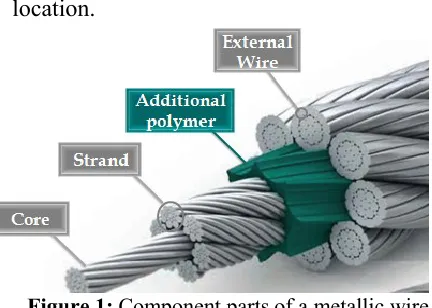
Wire ropes are widely used for mooring floating production systems and mobile units, whether their role is drilling [1], accommodation or the provision of some other support function. These uses separate into two distinct classes (Figure 1):
• Production systems which have permanent moorings where the ropes are only retrieved when due for discard;
• Mobile units which have temporary moorings that is retrieved and redeployed whenever the vessel is moved to a different location.
Figure 1:Component partsof a metallic wire
rope
These distinctions are significant with respect to the dominant degradation
mechanisms and opportunities for
inspection. Furthermore a higher degree of integrity is sought for permanent moorings.
International Journal of Research (IJR)
e-ISSN: 2348-6848, p- ISSN: 2348-795X Volume 2, Issue 07, July 2015Available at http://internationaljournalofresearch.org
aggression of environment (effects of rain, wind) and changes in random loads. When these movements are caused by stress variables, it concerns interfiled friction or friction induced by small displacements. This is exacerbated in areas of stress concentration by phenomena of wear, fatigue or corrosion, which are direct consequences of the modifications strong geometrical and mechanical characteristics of components [2].
Indeed, the detection of damage in broken internal or external wires is of extreme importance. However the situation may be complicated by multiple cuts that occur along the wire, especially in the presence of interfiled friction.
2. Problems related to cables
The geometry of some cables is so complex that the definition of areas interfilaire contact, or bends and twists in the wires before loading, require lengthy mathematical developments. Several authors have tried to solve this purely geometrical problem. Thus, in their study, Karamchett and Yuen [3] were interested in research of interfilaire contact points in a multi-strands cable. They presented many results of numerical applications of their model, which they varied the arrangement of wires in cable section. They also noted that loading of the cable changes the number and distribution of contact areas.
Lee and al. [4] are attached to express
geometric curvature and torsion, before loading in any constituent cables of an optionally complex cable section, when wound around a drum or pulley. The objective is to calculate stresses in the wires.
Out and Vonmorgen [5] treated sliding wound on a cylinder in bending wire. The subject of their model is considered as
flexible tube consisting of several layers which have a helical obvious analogy with cables, although the winding angle is much larger than wires in a cable. The approach chosen by authors is essentially geometric.
When the tube is bent, they define the maximum shift between two successive layers as the difference between the initial distorted helix and the geodesic line on the cylinder down (geodesic is the shortest line between two points remaining on a surface curve). Their theory is designed to calculate the landslide responsible for fatigue phenomena in this category of cables.
2.1. Corrosion protection from zinc
Whilst intact the zinc coating is effective in providing a simple protective barrier to the steel. But with time zinc is slowly dissolved where it is exposed, and its loss may be accelerated by external abrasion or at internal contacts between wires. Once steel is exposed the sacrificial protection begins involving a galvanic cell between the zinc and steel, via a seawater electrolyte.
The sacrificial process leads to further consumption of zinc. So dissolution is an essential part of the protection process bringing the zinc ions to the exposed steel surface, but underwater proceeds whether steel is exposed or not, at a rate depending on local conditions. Steel loss will not commence until all the available zinc within a short range has been dissolved. The snag here is that the zinc must be available which means that the anodic zinc and protected cathodic steel must be exposed to, and connected by, hydrous electrolyte, with a return electrical path through the metals.
International Journal of Research (IJR)
e-ISSN: 2348-6848, p- ISSN: 2348-795X Volume 2, Issue 07, July 2015Available at http://internationaljournalofresearch.org
exposed zinc on those wires has been dissolved. A typical pattern of corrosion which then follows is for the outer wires to corrode, not on the exposed crown, which is typically protected at this stage by zinc carbonate deposits, but along either side of the valley between them.
As a result, in a severe case of corrosion, outer wires become almost rectangular in section, standing on edge with the gaps between them filled with corrosion debris (Figure 2). At first sight, even to the experienced eye, such a rope appears comparatively undamaged as the outer surface looks to be in good condition.
Figure 2: Effects of external corrosion on 90 mm Class B galvanized mooring rope
A dilemma for the rope maker is whether to use a heavy lubricant that will exclude seawater from the interior. Such a policy will obviously protect the interior, but will prevent zinc from within the rope protecting the outer wires (Figure 3). It is of course normal practice to use such a heavy lubricant, and so the critical factor for the onset of steel dissolution is the time taken to dissolve and consume the external zinc (Figure 4).
Figure 3: corrosion and break-up of 76 mm ungalvanized mooring rope after five years
service
Figure 4: corrosion and break-up of 90 mm galvanized mooring rope after 7 years
2.2. Crushing and wear on a winch
The most common form of storage and tension control used for wire rope moorings is a winch onto which rope is wound in multiple layers. The large storage capacity of such winches is essential for mobile units, and can also be a factor in the installation of floating production systems (Figure 5).
International Journal of Research (IJR)
e-ISSN: 2348-6848, p- ISSN: 2348-795X Volume 2, Issue 07, July 2015Available at http://internationaljournalofresearch.org
The fluctuating tension in the rope induces elastic extension and recovery. Where the rope runs onto the winch this
fluctuating tension and associated
deformation is dissipated over an arc of contact extending back around the drum over a distance related to the tension levels.
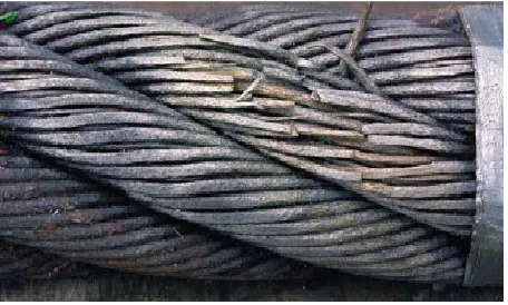
The small amplitude sliding of the rope relative to the supporting layers causes local wear, especially at the crossovers. Such wear can become so severe as to lead to significant numbers of localized wire breaks (Figure 6).
Figure 6: Damage caused where the tangent point was close to a crossover on a 70 mm
mooring line after 8 years of service
3. Numerical modeling of wire
ropes
Helical structures are widely used in
mechanical and civil engineering
applications. These structures are usually subjected to large loads which can lead to material degradations and cracks, associated with corrosion and mechanical fatigue. In this framework, non-destructive testing is a crucial tool for detection, localization and measurement of material discontinuities. The choice of appropriate technique depends on dimensions and accessibility of the structure.
Numerous works have been devoted to the modeling of static behavior of helical structures as springs and multi-wire cables under axial loads. For helical springs, an analytical model was proposed among others in Ancker and Goodier [6] and Wahl [7] considering the spring as an Euler– Bernoulli beam with pitch and curvature
corrections. Numerical approaches
describing the static behavior of helical springs have been also developed.
Among these works, a finite element model of half of a spring slice has been proposed in Jiang and Henshall [8]. The static behavior of seven-wire strands has been widely studied in literature. Various analytical models based on different assumptions have been proposed, such as the model of Costello [9] which is one of the most popular. These models are reviewed compared in Jolicoeur and Cardou [10] and Ghoreishi [11]. Besides, numerical models relying on the finite element method were developed.
Some of them are based on beam elements Durville [12], Paczelt and Beleznai [13], in which superconducting cables composed of a large number of strands are studied.
In order to obtain a good representation
of the geometry as well as the displacement
solution, which may involve bending
phenomena, quadratic elements are
employed. This leads to models which can
be computationally expensive, when the
model axiallength is about the pitch length.
Therefore, as soon as the loading fulfills
helical symmetry, one can take benefit of this property to reduce the model size.
International Journal of Research (IJR)
e-ISSN: 2348-6848, p- ISSN: 2348-795X Volume 2, Issue 07, July 2015Available at http://internationaljournalofresearch.org
can be actually considered more efficiently. Thus the model can be reduced to a 2D one, i.e. a cross-section model. This requires formulating the homogenization theory in a twisted coordinate system.
This technique then allows the computation of the static prestressed state of helical structures (single wire and multi-wire) from the solution of a 2D problem. Let us mention that an advanced analytical 2D model has been proposed in Argatov [15]. This model takes into account Poisson’s effect, contact deformation and allows obtaining the overall strand stiffness as well as local contact stresses. In this reference, plane strain was assumed to formulate the 2D problem while in the present work helical symmetry is used.
4. Description and characterization
of wires geometries
It is well known that solution by
mechanical problems finite element
interactional contact, which generally uses implicit integration schemes, is often affected by numerical problems due to poor convergence.
The deformation of cables is an example of problems with multiple contacts interaction wires, especially if the number of strands in cable is high enough. In this context, several finite element codes were used to solve this problem the majority incorporates temporal integration schemes.
Code with explicit finite element solvers has been applied to problems of cables as ABAQUS / Explicit. One of difficulties in applying the Finite element codes is to find optimal loading speed is slow enough to take into account dynamic effects.
Our numerical simulation is performed using computer code Abaqus. This program aims to provide a computational tool easy to handle for recessed cables for analysis, taking into account the lagged effects of applied force and displacement.
4.1. Geometry-Setting
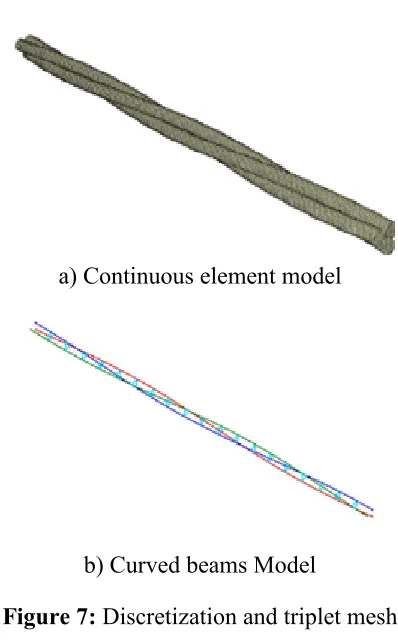
In the first stage of our study, this analysis will focus on a triplet consisting of three cable strands (6 mm diameter) (Figure 7).
a) Continuous element model
b) Curved beams Model
Figure 7: Discretization and triplet mesh
International Journal of Research (IJR)
e-ISSN: 2348-6848, p- ISSN: 2348-795X Volume 2, Issue 07, July 2015Available at http://internationaljournalofresearch.org
Table 1: Geometrical and mechanical characteristics of triplet
Diameter of cable 6 mm Height of torsion 45 mm Young’s modulus 117 GPa Poisson’s ratio 0,3 Wire diameter of strand 1,6 mm Mass per unit length 0,143 kg/m
4.2. Maillageand Boundary Conditions
In order to obtain equations governing motion of triplet, we have developed a numerical approach, using Abaqus software (Figure 8).
If we consider the triplet as a single spiral beam, its mechanical behavior is governed by the system of equations.
Finite element method, adopted in this study, is calibrated by a suitable calculation of mechanical response applied to cables. Mesh elements are finely refined elements including special wires.
For all models, symmetry properties are used when it’s available. Thus, for 3D geometries, we have two planes of symmetry: the plane containing elements of beam and the perpendicular plane passing through axis of revolution.
The strands are discretized with 3D linear triangular elements. The model has 7450 nodes distributed in prismatic elements.
All models developed reflect large deformations, large displacements and contact interaction between strands. Both models of elastic and elastic-plastic materials were considered.
Figure 8: Boundary conditions of force and timing of the triplet
The simulated load is a tensile load along longitudinal axis of the wire, to avoid bending or twisting parasite and to ensure that the tractive force is perfectly aligned.
Figure 9 explains the comparison results of the displacement according to the uniaxial tensile force applied by the continuous model elements and model of the curved beams.
International Journal of Research (IJR)
e-ISSN: 2348-6848, p- ISSN: 2348-795X Volume 2, Issue 07, July 2015Available at http://internationaljournalofresearch.org
Figure 9: Comparison of displacement results based on the force applied between the model of curved beams and model of
continuous elements
From a value of 20 KN of force, the two curves confirm stagnation of travel (Uz), to the breaking force which in this case corresponds to 35 KN.
4.3. Moment-rotation angle
The comparison between the variation angles of rotation values applied to the triplet according to time shows good agreement between the two models (Figure 10).
Analysis of the two curves (Figure 10) shows that the time becomes larger gradually as the angle of rotation increases, until the value 0.03 N.m, where the model of the curved beams is slightly above the continuous model.
Figure 10: Comparison of rotation angle results according to the time between model of curved beams and model of continuous
elements
5. Comparison of experimental and
numerical models
5.1. Load-displacement curve
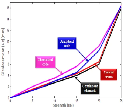
This part aims to establish a comparison between the two models with other from the literature. The results of comparison which describes the evolution of the displacement versus the applied force are shown in figure 11.
The analytical-numerical comparisons show good agreement at the elastic phase, providing a powerful tool for a quick estimate of the axial torsion behavior. Going up the levels, analytical relationships lose accuracy due to the fact that they were made
under restrictive assumptions and
International Journal of Research (IJR)
e-ISSN: 2348-6848, p- ISSN: 2348-795X Volume 2, Issue 07, July 2015Available at http://internationaljournalofresearch.org
Figure 11: Comparison of displacement curves charging for different models
We note that for quick calculations cables with low coefficients of friction and negligible rigidities, the theoretical model may be most appropriate for the gain in time it has (simple mesh and reduced number of nodes). In the case of multi-layer cables with significant rigidities coefficients, the model of continuous elements will be best suited for its precision and refined mesh (figure 11).
5.2. Curve point angle of rotation
The curves shown in figure 12 give the same manners provided for the twist that for traction.
Analytical-numerical comparisons show good agreement at the elastic phase to the three models: analytical continuous elements and curved beams. Therefore in the case of complex cable, model continuous elements will be the right choice for its accuracy.
Figure 12: Comparison of angles of rotation-time curves for different models
6. Conclusion
In order to predict the lifetime of the wire rope, it is necessary to select the appropriate numerical model to describe the lifetimes of samples cables.
Two models are typically used for describing the life of cables which are either the beam distribution curve or pattern of continuous elements. The intended effect of these models is to predict the median life span by using existing experimental data or lab results. We used these models in comparison with others to represent the stiffness and strength of the cables.
The metal lifting cables must be
maintained regularly, the type of
maintenance depends on the class of hoist, its use and the type of cable. It should be noted that regular maintenance considerably increases the lifetime of a metal lifting cable.
References :
[1.]A. CHOUAIRI, M. EL GHORBA,
A. BENALI « Etude du
comportement mécanique des câbles métalliques de levage : Examen,
dépose et rebus » Editions
International Journal of Research (IJR)
e-ISSN: 2348-6848, p- ISSN: 2348-795X Volume 2, Issue 07, July 2015Available at http://internationaljournalofresearch.org
pages, ISBN-13: 978-613-1-51699-3,
ISBN-10: 6131516995, EAN:
9786131516993, (25-12-2012).
[2.] A. CHOUAIRI, M. EL GHORBA,
A. BENALI, E. BOUDLAL
«Analytical approach of availability and maintainability for structural lifting cables using reliability-based optimization » International Journal
of Engineering and Science
(RESEARCH INVENTY), ISSN: 2278-4721, Vol. 1, Issue 1, (August 2012), PP 08-17.
[3.]Karamchett, Y.S.D. and W.Y. Yuen,
1979. Contact problems in wire ropes. Transactions of the ASME, pp: 702-710.
[4.]Lee, W.K., N.F. Casey and T.G.F.
Gray, 1987. Helix geometry in wire rope. Wire Industry, pp: 461-468.
[5.]Out, J.M. and B.J. Vonmorgen,
1997. Slippage of helical reinforcing on a bent cylinder. Engineering Structures, pp: 507-515.
[6.]Ancker, C.J. and J.N. Goodier, 1958.
Pitch and curvature corrections for helical springs. Journal of Applied Mechanics, Vol. 80, pp: 466–470.
[7.]Wahl, A.M., 1963. Mechanical
springs. 2nd Edn., New York: Mc Graw-Hill, Inc, Vol. 7, pp: 92-102.
[8.]Jiang, W.G. and J.L. Henshall, 2000.
A novel finite element model for helical springs. Finite Elements in Analysis and Design, pp: 363–377.
[9.]Costello, G.A., 1977. Theory of wire
rope. Springer book.
[10.]Jolicoeur, C. and A. Cardou, 1991.
A numerical comparison of current mathematical models of twisted wire cables under axisymmetric loads.
Journal of Energy Resources
Technology, pp: 241–249.
[11.]Ghoreishi, S.R., T. Messager, P.
Cartraud and P. Davies, 2007. Validity and limitations of linear analytical models for steel wire strands under axial loading, using a 3d fe model. International Journal of Mechanical Sciences, pp: 1251– 1261.
[12.]Durville, D., 1998. Modélisation du
comportement mécanique de câbles métalliques. Revue Européenne Des Eléments Finis, pp: 9–22.
[13.]Páczelt, I. and R. Beleznai, 2011.
Nonlinear contact-theory for analysis of wire rope strand using high-order approximation, pp: 1004–1025.
[14.]Messager, T. and P. Cartraud, 2008.
Homogenization of helical beam-like structures: Application to
single-walled carbon nanotubes.
Computational Mechanics, pp: 335– 346.
[15.]Argatov, I., 2011. Response of a
wire rope strand to axial and
torsional loads: Asymptotic