Dc Component Minimization By Integral Method With Transformerless
Three-Phase Grid-Connected Pv Systems
1
Yammanur Sai Sunil,
2C. Kiran Kumar
1
M.Tech(EPS) Student, Dept. of EEE, ST. MARK Group Of Educational Institutions, Affiliated to JNTUA , A.P
2
Assistant Professor,Dept. of EEE, ST. MARK Group Of Educational Institutions, Affiliated to JNTUA, A.P
ABSTRACT-
The commercially available solar cells have efficiency between 16-20%, the power electronic interface that connects it to the utility should be extremely efficient and dependable. Based on galvanic isolation, photovoltaic (PV) inverters can be classified as with line frequency transformers and high frequency transformers. Line frequency transformers make the whole system bulky and less efficient. High frequency transformers have more than one power stages and increase the system complexity . Need for a transformer less inverter is imminent in this regard. A transformer less inverter reduces the cost, size, weight and volume and increases the efficiency of the whole system. The dc component can cause line-frequency power ripple, dc-link voltage ripple, and a further Second-order harmonic in the ac current. This paper has proposed an effective solution to minimize the dc component in three-phase ac currents and developed a software-based approach to mimic the blocking capacitors used for the dc component minimization, the so-called virtual capacitor. The “virtual capacitor” is achieved by adding an integral of the dc component in the current feedback path. A method for accurate extraction of the dc component based on double time integral, as a key to achieve the control, has been devised and approved effective even under grid frequency variation and harmonic conditions. A proportional-integral-resonant controller is further designed to regulate the dc and line-frequency component in the current loop to provide precise control of the dc current.
I. LITERATURE REVIEW AND RELATED WORKS
effectiveness of the design procedure both of the LCL-filter and of the controllers. The performance of the overall system is good both in the low and high frequency ranges[3].
II. EXISTING SYSTEM- There are many
problems related to Transformerless structures, like dc element within the electrical converter output (grid) current, ground run current (due to common-mode voltage and parasitic capacitance), and also the voltage-level mate between the electrical device (inverter) and grid. Among them, the dc element will have an effect on the normal system operation and cause safety issues. Standards have so been established in several countries to limit the extent of the dc element.
DISADVANTAGE OF EXISTING
SYSTEM
The dc component can have negative impacts on the power system in the following ways [9], [11]:
1) The dc component can affect the operating point of the transformers in the power system. The transformer cores are driven into unidirectional saturation with consequent larger excitation current. The service lifetime of the trans-former is reduced as a result with further increased hysteresis and eddy current losses and noise.
2) The dc component can circulate between inverter phase legs as well as among inverters in a paralleled configuration. The dc component circulation affects the even current and loss distribution among paralleled inverters.
3) The dc component injected to the grid can affect the nor-mal operation of the loads connected to the grid, for example, causing torque ripple and extra loss in ac motors. 4) The corrosion of grounding wire in
substations is intensified due to the dc component.
III. PROPOSED SYSTEM-
A. Virtual Capacitor Concept of Single-Phase Grid-Connected PV Inverters
One way to block the dc component is to put a capacitor C in series with the ac side of the inverter. However, in order to reduce the capacitive reactance at other frequencies, the capacitor value needs to be large, which increases the size and cost of the system. This series capacitor may also affect the system dynamic response and reduce transmission efficiency. Nevertheless, the physical capacitor can be re-placed by software-based method and advanced control strategy which mimics the operation of the series capacitor in a single-phase PV system
Fig.1: Equivalent transformation of the current control loop with virtual capacitor concept
B. DC Component Minimization in Three-Phase
PV Inverters With DC-Component Feed-Forward and PIR Controllers
Based on the above analysis, this section investigates how to implement the “virtual capacitor” concept for three-phase systems in the stationary frame and to be further integrated to the standard PV inverter current control loop in the dq frame with a PIR controller.
The standard three-phase inverter current loop normally adopts a proportional-integral (PI) controller in the dq frame to regulate the d-axis and q-axis currents. The PI controller in dq frame is equivalent to a proportional-resonant (PR) controller in the stationary abc frame, given the resonant frequency of the R controller is selected as the line frequency (rotational frequency). Therefore, the current
where the variables with the subscript abc denote the vectors of the three-phase voltages and currents. The gain of the pulse width modulator (KPW M ) is assumed to be unity to simplify the derivation. The PR controller is effectively a proportional (P) controller if only the dc component is taken into account, and the diagram for the dc component, where the variables with the subscript abc0 denote the vectors of the three-phase dc components. If the capacitor voltage feedback terminal (1/Cs) is moved to the feedback path, where KP is the proportional gain, the physical blocking capacitor C can then be replaced with an integral and a feed-forward term (algorithm). Thus, the virtual capacitors are achieved in a three-phase PV system in the stationary a-b-c frame. To achieve the zero steady-state error for the dc component, replaces the P controller) with an integral (I) controller. Then, in order to apply the dc component minimization method to the standard dual closed-loop control system in a synchronous frame, is then transformed to a mixed abc and dq frame. The reference current i*abc0 , the grid voltage eabc0 , and the current controller is implemented in synchronous frame (i*abc0 , eabc0, and the I controller are transformed into i∗
dq1 , edq1 , and the R controller, respectively). The “virtual capacitor” in the feedback path is still implemented in the stationary a-b-c frame.
C. DC COMPONENT EXTRACTION
BASED ON SLIDING WINDOW
ITERATION
In the control strategy shown in Fig. 2, an accurate dc component measurement and extraction is the key to implement the virtual capacitor concept and achieve the overall dc component minimization. Compared with the ac component, the dc component is very
small and an accurate dc component extraction is challenging. In PV inverters, the Hall-effect cur-rent sensors are widely used to measure the ac-side currents
(including both ac and dc components) due to their smaller size, isolated output, and wide bandwidth (e.g., from dc to several hundred kilohertz). In this paper, an integral method based on the sliding window iteration algorithm is used to accurately extract the dc component from the ac-side currents.
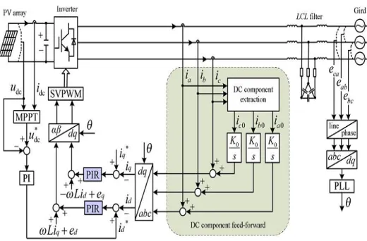
Fig 2: DC component minimization strategy based on dc component feed-forward and PIR controllers.
on the sliding window iteration algorithm is used to accurately extract the dc component from the ac-side currents.
Taking the ac-side Phase A current ia , for
example, ia can be expressed as in (1) if
considering both the dc component and other ac components of different frequencies (e.g., harmonics)
ia = ia0 + ∑ Ih sin(2πhf1 t + ϕh ) ----(1) h = 1,2,3•••
---(2)
When T = T1 = 1/f1 , the second term in the right side of (2) becomes
---(3)
Hence, with (2) and (3), the dc component ia0 can be obtained by
---(4) The next step is to implement the expression in (4) to obtain the dc component ia0 accurately without significant calculation
burden. If assuming the number of sampling times in a fundamental period (T1 ) is N, dt in (4) can be substituted by the sampling interval t and t = T 1/N . If τ is defined as t/N, then Ia (kτ ) is the kth sampling value. Substituting the definite integration in (4) by the accumulation of the integrand, the discrete expression of ia0 is given by
---(5)
To achieve a real-time dc component extraction, (5) should accumulate the sampling values for N–1 times in one fundamental period. The amount of calculation is therefore significant given a high sampling frequency. To decrease the amount of calculation, sliding window iteration is used in (6) to replace (5)
---(6) where Ncur is the sliding pointer which represents the current
sampling point. After completing the summation of one fundamental period for initialization, N–1 additions of (5) is simplified as one addition and one subtraction of (6). As a result, the
amount of calculation is reduced.
C. PIR CONTROLLER DESIGN
As mentioned, when taking the dc component in the ac-side currents into account, the current loop in the dq frame is com-posed of both a dc component and a line-frequency component (negative sequence). The dc component in the rotational frame comes from the line-frequency ac components in the phase cur-rents. The line-frequency component in the rotational frame
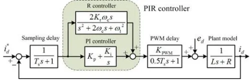
Fig. 3. d-axis current control loop based on the PIR controller
comes from the dc component in the phase currents. To provide an effective control for both dc and line-frequency signals in the dq frame, a proportional-integral-resonant (PIR) controller is used. Taking the d-axis current control loop, for example, considering the sampling delay and the PWM delay, the current control loop based on the PIR controller is shown in Fig.3 where Ts is the
sampling period, Kp is the proportional gain, Ki is
the integral gain, and Kr is the resonant gain. ω1 is the resonant (center) frequency of the R controller, which is the same as the line frequency in this case. ωc is the cutoff frequency
In Fig. 3, the PI controller is used to regulate the dc component transformed from the fundamental currents. The R controller is used to regulate and minimize the line-frequency component transformed from the dc component. The parameters of the PI controller should be set to guarantee a good dynamic and steady-state performance of the current loop. The parameters of the R controller are set for the dc component minimization.
An infinite gain at the resonant frequency of the R controller can eliminate the steady-state error. In the improved R controller with 2ωc added to
the denominator as shown in Fig. 3, the gain at the resonant frequency is limited yet with improved performance under line-frequency fluctuation. Nevertheless, the gain can be adjusted by Kr . Regarding ωc , smaller ωc
provides better frequency selectivity but difficult for digital implementation. Larger ωc leads to a
wider bandwidth around the resonant frequency and a better robustness for the frequency deviation. However, the gain at the resonant frequency will be lower with a subsequent larger steady-state error.
IV. SIMULATION RESULTS
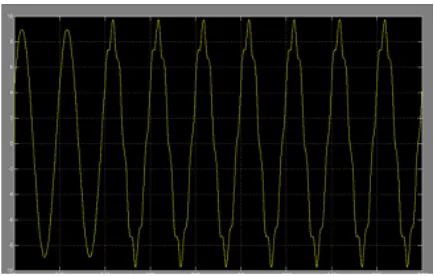
Fig 4: Grid current waveforms with DC component
Fig 5: Minimized dc component of Grid current waveforms by single integral
Fig 6: Minimized dc component of Grid current waveforms by double integral.
EXTENSION WITH FUZZY CONTROLLER
Fig 7: Minimized dc component of Grid
Fig 8: Minimized dc component of Grid
current waveforms by double integral with fuzzy controller
V. CONCLUSION
This project has presented an effective method to minimize the dc component in a three-phase Transformerless grid-connected PV system. The dc component can introduce line-frequency power ripple in the system and further cause dc-link voltage ripple and second-order harmonics in the ac currents. A “virtual capacitor” approach has been implemented to minimize the dc component via a feed-forward of the dc component. The dc component can be accurately obtained using the sliding window iteration and double time integral even under frequency variation and harmonic conditions. A PIR controller has been designed to enable the precise regulation of both the dc and line-frequency components in the d-q frame.
The proposed method can be well adopted in the existing PV systems for dc component minimization using the sliding window iteration and double time integral even under frequency variation and harmonic conditions for component extraction and Minimization of dc-component feed forward term as well as the resonant controller in the current control loops.
REFERENCES
41, no. 5, pp. 1292–1306, Sep./Oct. 2005.
[2] A. Ahfock and A. J. Hewitt, “DC magnetisation of transformers,” IEE Proc.-Electr Power Appl., vol. 153, no. 4, pp. 601–607, Jul. 2006.
[3] M. Armstrong, D. J. Atkinson, C. M. Johnson, and T. D. Abeyasekera, “Auto-calibrating DC link current sensing technique for transformerless, grid connected, H-bridge inverter systems,” IEEE Trans. Power Electron., vol. 21, no. 5, pp. 1385–1393, Sep. 2006.
[4] T.-F. Wu, H.-S. Nien, H.-M. Hsieh, and C.-L. Shen, “PV power injec-tion and active power filtering with amplitude-clamping and amplitude-scaling algorithms,” IEEE Trans. Ind. Appl., vol.
43, no. 3, pp. 731–741, May/Jun. 2007.
[5] V. Salas, E. Ol´ıas, M. Alonso, and F. Chenlo, “Overview of the legislation of DC injection in the network for low voltage small grid-connected PV systems in Spain and other countries,” Renewable Sustainable Energy Rev., vol. 12, no. 2, pp. 575–583, Feb. 2008.
[6] R. Gonzalez, E. Gubia, J. Lopez, and L. Marroyo, “Transformerless single-phase multilevel-based photovoltaic inverter,” IEEE Trans. Ind. Electron., vol. 55, no. 7, pp. 2694–2702, Jul. 2008.
[7] W. M. Blewitt, D. J. Atkinson, J. Kelly, and R. A. Lakin, “Approach to low-cost prevention of DC injection in transformerless grid connected inverters,” IET Power Electron., vol. 3, no. 1, pp. 111–119, Jan. 2010.
[8] O. Lopez, F. D. Freijedo, A. G. Yepes, P. Fernandez-Comesaa, J. Malvar, R. Teodorescu, and J. Doval-Gandoy, “Eliminating ground current in a transformerless photovoltaic application,” IEEE Trans. Energy Convers., vol. 25, no. 1, pp. 140–147, Mar. 2010.
[9] B. Wang, X. Guo, H. Wu, Q. Mei, and W. Wu, “Real-time DC injection measurement technique for transformerless PV systems,” in Proc. IEEE 2nd Int. Symp. Power Electron. Distrib. Generation Syst., Hefei, China, Jun. 2010, pp. 980–983.
three-“Highly efficient single-phase transformerless inverters for grid-connected photovoltaic systems,” IEEE Trans. Ind. Electron., vol. 57, no. 9, pp. 3188– 3128, Sep. 2010.
[12] G. Buticchi, E. Lorenzani, and A. Fratta, “A new proposal to eliminate the DC current component at the point of common coupling for grid connected systems,” in Proc. IEEE 36th Ann. Conf. Ind. Electron. Soc., Glendale, USA, Nov. 2010, pp. 3244– 3249.
13] F. Berba, D. Atkinson, and M. Armstrong, “Minimization of DC current component in transformerless Grid-connected PV inverter application,” in
Proc. 10th Int. Conf. Environ.Elect. Eng., Rome, Italy, May 2011, pp. 1–4.
[14] W. Li, L. Liu, T. Zheng, G. Huang, and S. Hui, “Research on effects of transformer DC Bias on negative sequence protection,” in Proc. Int. Conf. Adv. Power Syst. Automat. Protection, Beijing, China, Oct. 2011, pp. 1458–1463.
[15] F. Berba, D. Atkinson, and M. Armstrong, “A review of minimization of output DC current component methods in single-phase grid-connected inverters PV applications,” in Proc. 2nd Int. Symp. Environ. Friendly Energies Appl., Tyne, U.K., Jun. 2012, pp. 296–301.
[16] E. Koutroulis and F. Blaabjerg, “Design optimization of transformerless grid-connected PV inverters including reliability,” IEEE Trans. Power Electron., vol. 28, no. 1, pp. 325–335, Jan. 2013.
[17] B. Gu, J. Dominic, J. Lai, C. Chen, T. LaBella, and B. Chen, “High reliability and efficiency single-phase transformerless inverter for grid-connected photovoltaic systems,” IEEE Trans. Power Electron., vol. 28, no. 5, pp. 2235–2245, May 2013.
[18] Y. Shi, B. Liu, and S. Duan, “Eliminating DC current injection in current-transformer-sensed STATCOMs,” IEEE Trans. Power Electron., vol. 28, no. 8, pp. 3760–3767, Aug. 2013.
Y.SAISUNIL
MTech (EPS) student, Dept. of EEE, ST. MARK Group Of Educational Institutions, Affiliated to JNTUA, A.P
C.KIRAN KUMAR M.Tech Assistant Professor, Dept. of EEE, ST. MARK Group Of Educational Institutions, Affiliated to JNTUA, A.P