Western University Western University
Scholarship@Western
Scholarship@Western
Electronic Thesis and Dissertation Repository
10-24-2013 12:00 AM
Web-based Simulation and Training Environment for
Web-based Simulation and Training Environment for
Laparoscopic Camera Calibration
Laparoscopic Camera Calibration
Kartik ThakoreThe University of Western Ontario
Supervisor Hanif Ladak
The University of Western Ontario
Graduate Program in Biomedical Engineering
A thesis submitted in partial fulfillment of the requirements for the degree in Master of Engineering Science
© Kartik Thakore 2013
Follow this and additional works at: https://ir.lib.uwo.ca/etd Part of the Bioimaging and Biomedical Optics Commons
Recommended Citation Recommended Citation
Thakore, Kartik, "Web-based Simulation and Training Environment for Laparoscopic Camera Calibration" (2013). Electronic Thesis and Dissertation Repository. 1769.
https://ir.lib.uwo.ca/etd/1769
This Dissertation/Thesis is brought to you for free and open access by Scholarship@Western. It has been accepted for inclusion in Electronic Thesis and Dissertation Repository by an authorized administrator of
i
WEB-BASED SIMULATION AND TRAINING ENVIRONMENT FOR LAPAROSCOPIC CAMERA CALIBRATION
Thesis format: Monograph
by Kartik Thakore
Graduate Program in Biomedical Engineering
A thesis submitted in partial fulfillment of the requirements for the degree of
Master of Engineering Science
The School of Graduate and Postdoctoral Studies The University of Western Ontario
London, Ontario, Canada
ii
Abstract
Endoscopic cameras are increasingly employed in image-guidance procedures, where the video images must be registered to data from other modalities. However, such cameras are susceptible
to distortions, requiring calibration before images can be used for registration, tracking and 3D reconstruction. Camera calibration is learned in a laboratory setting, where configuring and adjusting the physical setup is tedious and not necessarily conducive to learning. A centralized resource that utilizes 3D interactive components needs to be available for training on camera calibration. In this project, a web-based training environment for camera calibration is implemented called SimCAM. SimCAM was developed using the Web Graphics Library (WebGL), Open Computer Vision (OpenCV) library, and custom software components. WebGL and OpenCV were used to simulate camera distortions and the calibration task. The main contributions include the implementation and validation of SimCAM. SimCAM was validated with a content validity study, where it was found to be useful as an introduction to camera calibration. Future work involves improving the supporting material and implementing more features, such as uncertainty propogation.
iii
Acknowledgments
I would like to thank my advisors, Dr. Ladak and Dr. Peters for their continued patience throughout
my program. I would also like to thank both Dr. Ladak and Dr. Peters for their critique of my work
and writing. I have learned an incredible amount, with regards to writing, presenting and analysis
for which I am eternally grateful. Additionally I would like to thank Alireza Rohani, Arefin
Shamsil, Caiwen Huang, Diego Cantor, Dr. Agrawal, Dr. Barron, Dr. Bureau, Dr. Chen, Dr.
Eagleson, Dr. Katchabaw, Dr. Parraga, and Uditha Jayarathne, for their support, advice and
valuable feedback. Also I would like to thank my family for their continued support.
Finally I would like to thank my dear friend Stacy Roberson, without her this thesis would not
iv
Table of Contents
Abstract ... ii
Acknowledgments... iii
Table of Contents ... iv
List of Tables ... vi
List of Figures ... vii
List of Appendices ... xi
List of Abbreviations and Acronyms ... xii
List of Symbols ... xiv
1 Introduction ... 1
1.1 Motivation ... 1
1.2 Cameras... 2
1.2.1 Components of a Camera ... 2
1.2.2 Pinhole Camera Model ... 3
1.2.3 Intrinsic Parameters ... 6
1.2.4 Extrinsic Parameters ... 9
1.3 Camera Calibration ... 10
1.3.1 Calibration Software ... 11
1.4 Available Training for Camera Calibration ... 11
1.5 Objectives ... 11
2 Methodology ... 12
2.1 System Users ... 12
v
2.3 Specifications ... 12
2.3.1 Functional Specifications ... 13
2.3.2 Non-functional Specifications ... 13
2.4 Implementation ... 14
2.4.1 Programming Languages & Libraries ... 15
2.4.2 Architecture & Design ... 19
3 Results ... 49
3.1 Introduction ... 49
3.2 Time Spent on Tutorial ... 49
3.3 Content Validity ... 49
3.3.1 Section A: Specific content validity questions ... 50
3.3.2 Section B: Determining attitudes on design decisions ... 53
3.3.3 Section C: Measuring difficulty of simulator ... 54
3.3.4 Section D: Ensuring all simulation components worked ... 54
3.3.5 Additional Comments ... 55
3.4 Expert Determination ... 56
3.4.1 Quiz Results ... 57
4 Conclusion & Future Work ... 58
Bibliography ... 61
Appendices ... 65
vi
List of Tables
Table 3-1: Mean vs. Median of each question in Section A ... 51
vii
List of Figures
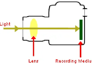
Figure 1-1: Simple Camera Components: Light enters the camera and is focused through a lens system on the recording medium, which stores the image. ... 3
Figure 1-2: Camera image acquisition where a pinhole in a box acts as a lens for the light which is projected on the back of the box – source: Wikimedia commons. ... 3
Figure 1-3: Depiction of a pinhole camera in the perspective projection model [14] that projects 3D world points P to 2D image points p, where f is the focal length. ... 4
Figure 1-4: Example of radial distortion, applied on the left image. The left image is also the ideal correction of the radially distorted image. ... 7
Figure 1-5: The distorted image corrected with coefficients (-10, -100, -1000) for the radial distortion correction equation applied. ... 7
Figure 1-6: Example of tangential distortion, applied on the left image. The left image is also the ideal correction of the tangentially distorted image. ... 8
Figure 1-7: The distorted image corrected with coefficients (-0.1, 0) for the tangential distortion correction equation applied. ... 9
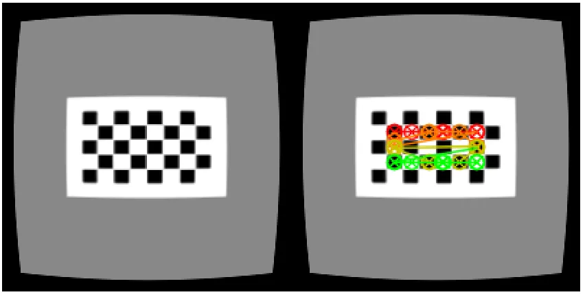
Figure 1-8: Image on the right shows extracted features from the corners of the calibration grid from the left image. ... 10
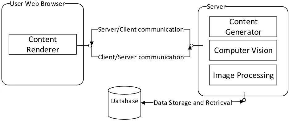
Figure 2-1: System architecture overview of SimCAM, showing the client (code deployed on the user’s Web Browser), server and database component. ... 14
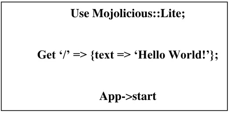
Figure 2-2: Mojolicious descriptive languages for web services. This example shows a simple <<GET>> request to the root URL path that returns the text ‘Hello World!’. ... 17
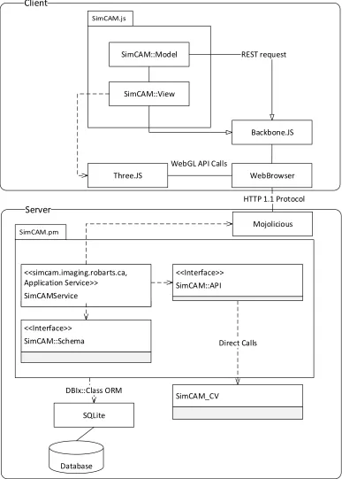
Figure 2-3: SimCAM Architecture that shows specific components responsible for interfaces and communication between the client and the server. ... 22
viii
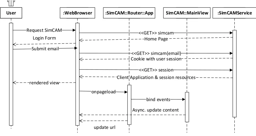
Figure 2-5: Initialization sequence of the client (SimCAM::Router::App) on the WebBrowser. The User triggers the process by requesting the service URL through the WebBrowser. The request triggers the SimCAMService on the server to provide the client application payload, which is then initialized on the WebBrowser when the page is loaded. ... 25
Figure 2-6: Class diagram describing session resource provide by SimCAM::Service. ... 26
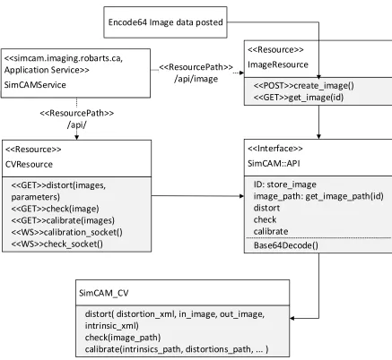
Figure 2-7: Class diagram describing the image and computer vision resource in
SimCAMService. ... 27
Figure 2-8: Class diagram describing the interface between the client and service via REST and
Backbone::Model and its children in the SimCAM::Collection and SimCAM::Model namespace. ... 28
Figure 2-9: Paper prototype of basic user interface template for each milestone. The milestone progress bar shows how far along the user is in the study. The content material is shown in the center with tutorial and interactive content. Finally a quiz is presented at the bottom. ... 30
Figure 2-10: Paper prototyping of GUI Design for 3D interactive components. The camera view shows the current camera’s view. The 3D workspace is where the user interacts with the camera and calibration grid. The side menu provides buttons for camera calibration results and capturing images. The captured images are shown in the additional results area. Finally the
rotation/position manipulator shows the rotation and position of the current select object that can also be edited... 31
Figure 2-11: Class diagram describing the class hierarchy for views in SimCAM. All SimCAM::Views are implementations of Backbone::View and initiated by the
SimCAM::Router::App. ... 32
Figure 2-12: Hierarchy of implemented components of SimCAM: Simulation, Interactive, Feedback, Tutorial Materials and Validation computers ... 34
ix
Figure 2-14: Distortion simulation with controls on the side menu where the user can adjust the parameters for radial and tangential distortions. ... 36
Figure 2-15: User interaction with calibration environment. (Step 1, A) Capture image with camera. Images appear in (Step 2, B). ... 37
Figure 2-16: Camera matrix manipulator widget. Users can change the focal length and principal points of the camera in the 3D environment above. ... 38
Figure 2-17: Camera pose manipulator. The user can adjust the rotation and translation matrix directly to the 3D environment in the same milestone. ... 39
Figure 2-18: Interactive webcam component that allows user to calibrate their web camera. They use their phones or printed paper to display an 8x5 calibration on their web camera. By clicking the capture button similar to the calibration environment in Figure 2-15. The captured images are shown in the bar on the bottom and the calibrated results in the results dialog (Figure 2-19) ... 40
Figure 2-19: Feedback popup dialog which shows the calibration parameters, graphs (Figure 2-20) and efficacy (Figure 2-21) of the current calibration attempts ... 41
Figure 2-20: Example of differencing the corrected and undistorted images. In the simulation environment the undistorted images are simulated camera views before the simulated distortion is applied. The distorted images are with simulated distortions applied, and the corrected images are with the calibration parameters used to correct the distorted image. The final efficacy of the calibration is based on the difference image of corrected and undistorted image. ... 42
Figure 2-21: Example of charted calibration parameters. Clicking on the legend values enables each series ... 43
Figure 3-1: Time spent on study vs. correct answers in the quiz, p=0.73. ... 57
Figure 3-2: Hours participant was awake vs. quiz score, p=0.36 ... 58
x
xi
List of Appendices
xii
List of Abbreviations and Acronyms
<<GET>> - HTTP GET request sent from the client to the server
<<POST>> - HTTP POST request sent from the client to the server
<<WS>> - HTTP WebSocket request that initiates a WebSocket between the client and server
2D – two-dimensional
3D - three-dimensional
API – Application programming interface
Bootstrap – HTML and CSS framework
C programming language – High level programming language with efficient data structures, CPU and memory usage
CPAN - Comprehensive Perl Archive Network
CPU - central processing unit
CRUD - basic create, read, update and delete operations on the database
CT - computed tomography
DBI - Database interface
DBIx::Class – Database interface extension library that marshals database tables into class
GPU - Graphics Processing Unit
GUI - Graphical User Interface
HTML5 – Hyper Text Markup Language 5th edition
xiii
MATLAB - high-level technical computing language and interactive environment
MIS - Minimally invasive surgeries
MRI - magnetic resonance imaging
MVC - model view controller architecture
MVP – model view presenter paradigm
OpenCV – Open Computer Vision library
OpenGL ES - a cross-platform API for full-function 2D and 3D graphics on embedded systems
ORM - object relational mapping
PET - positron emission tomography
RDBMS - Relational data base management system
REST - Representational state transfer
SimCAM – Name of system created and tested, sort for simulation camera
STD – Standard deviation
SQL - Structured Query Language
SQLite – Server less SQL database
Three.JS – JavaScript library that extends WebGL
WebBrowser – Software package that abstracts web browsers used by users
xiv
List of Symbols
𝐴 - Camera matrix that describes the transformation between 𝑃 and 𝑝
𝑎 – Aspect ratio, a ratio between the height and width of the image plane
(𝑐𝑥, 𝑐𝑦 ) - Principal point
𝑓 – Focal Length in camera matrix 𝐴
𝑘1, 𝑘2, 𝑘3− 3 coefficients for radial distortion correction equation
𝑃 - 3D world point (𝑋, 𝑌, 𝑍)
𝑝 – Image point (𝑢, 𝑣) or (𝑥, 𝑦)
𝑝1, 𝑝2– 2 coefficients that describe tangential distortion correction equation
𝑟 - The distance of an image point from the center or principal
[𝑅|𝑡] - Homogenous matrix of the camera’s rotation (𝑅) and translation (𝑡) relative to the origin point of the world
𝑠 - Arbitrary scalar scale factor for perspective camera model
(𝑢, 𝑣) or (𝑥, 𝑦) – 2D position coordinates in image
1
1
Introduction
1.1
Motivation
Minimally invasive surgeries (MIS) help to increase patient recovery and decrease complications, and have, in large measure, been enabled by the decreasing size of instruments and laparoscopic cameras. Images from laparoscopic cameras must be highly accurate and distortion free because they are often registered with images from other sources such as pre-operative computed tomography (CT) or magnetic resonance imaging (MRI) [1] [2]. Laparoscopic cameras can be effectively modeled as an ideal pinhole camera [3]. However, the precision and accuracy of MIS applications are affected by distortions because the optical system associated with a typical endoscope is not ideal [4]. Distortions are especially exacerbated as the camera is made smaller for minimally-invasive procedures, which can directly affect application results [5]. As a consequence, it is necessary to perform a calibration procedure to correct these distortions [6]. In addition to this distortion correction, a further calibration step must be performed to relate the pixels in the image to the three-dimensional space within which the image resides [7]. Most camera calibrations enable the intrinsic (distortion and focal length) and extrinsic (pose) parameters to be performed in a single calibration procedure [8].
The most common method of achieving such a camera calibration is to capture images of a known
grid pattern from multiple viewpoints. These images are then used to estimate the intrinsic parameters of the camera. Additional steps are then performed to estimate the transformation matrix that relates the 3D coordinate of the camera to those of the real world, also known as the extrinsic parameters. These camera parameters are described more in detail in section 1.2 [8].
Currently there are several camera calibration algorithms and software packages. Regardless of the algorithm however, calibration grid images remain a crucial component. Especially in medical imaging the OpenCV software package is used to perform camera calibration. Camera calibration is described in detail in section 1.3.
2
used to teach industrial camera calibration with a course [9]. Web based training for similar techniques have been found to be effective [10]. The motivation for the current work is that no self-directed 3D interactive camera calibration environment is available for graduate students online.
1.2
Cameras
Laparoscopic cameras, and cameras in general, are devices that record light scattered from objects in the real word and capture them to a screen. In medical imaging, laparoscopic cameras provide visual inputs that can be used to drive a variety of applications. Medical imaging tasks such as registration, tracking and visualization are a few of the applications that depend on camera calibration ( [1], [2], [4] ).
For example, medical registration applications involve alignment of features and images captured from cameras and other modalities [1]. Medical imaging modalities used to acquire images of the body include radiography (X-ray, Computer Tomography), magnetic resonance imaging (MRI), and positron emission tomography (PET), with laparoscopic cameras also falling into this category ( [11], [12]).
1.2.1 Components of a Camera
3
Figure 1-1: Simple Camera Components: Light enters the camera and is focused through a lens
system on the recording medium, which stores the image.
Figure 1-2: Camera image acquisition where a pinhole in a box acts as a lens for the light which is projected on the back of the box – source: Wikimedia commons.
1.2.2 Pinhole Camera Model
4
extrinsic parameters describe the external features of the camera such as the orientation and position of the camera [15].
Perspective projection model
In the pinhole camera model, the ideal relationship between the 3D world point 𝑃 = (𝑋, 𝑌, 𝑍) and the camera’s capture point 𝑝 = (𝑢, 𝑣) is modeled as a perspective projection. In the perspective
projection model (Figure 1-3) the optical axis is collinear with the Z axis. The optical centre of the camera is defined to be positioned at the origin of the 3D (world) coordinate system, and where the image plane contains the projection of the 3D word point P onto the 2D image point (𝑝). The focal length of the camera is the distance between the optical centre and the image plane. Finally the centre of the image plane is the principal point that decides the offset of the image captured [16].
5
The model the projection of a 3D world point 𝑃 = (𝑋, 𝑌, 𝑍) to the 2D image point 𝑝 = (𝑢, 𝑣) can
be written as a relationship (1-1).
𝑢 =
𝑋𝑓
𝑍
, 𝑣 =
𝑌𝑓
𝑍
(1-1)This relationship can be reformulated in matrix notation as denoted in (1-2).
[ 𝑢 𝑣 1] = [
𝑓 0 0 0 0 𝑓 0 0 0 0 1 0
] [ 𝑋 𝑌 𝑍 1 ] (1-2)
Equation (1-1) can be amended (Equation 1-3) to account for the principal point (𝑐𝑥, 𝑐𝑦), which is
the offset of the image plane capture.
[ 𝑢 𝑣 1] = [
𝑓 0 𝑐𝑥 0
0 𝑓 𝑐𝑦 0
0 0 1 0
] [ 𝑋 𝑌 𝑍 1
] (1-3)
This principal point is usually at the centre of the image plane. For example if the image plane is 600 pixels in width and 300 pixels in height, the principal point would be (300, 150) pixels. The
transformation matrix ([
𝑓 0 𝑐𝑥 0
0 𝑓 𝑐𝑦 0
0 0 1 0
]) is called the camera matrix (
𝐴
in Equation (1-4) ).𝐴 [
𝑥
𝑦
𝑧
1
] = [
𝑢
𝑣
1
]
(1-4)The camera matrix can also be adapted (1-5) to account for additional parameter such as the
aspect ratio (𝑎, the ratio between the height and width) of the image plane.
[ 𝑢 𝑣 1] = [
𝑎𝑓𝑥 0 𝑐𝑥 0
0 𝑓𝑦 𝑐𝑦 0
0 0 1 0
6
1.2.3 Intrinsic Parameters
Linear Intrinsic Parameters
The components of the camera matrix (
𝐴
in Equation (1-4)) are the linear intrinsic parameters ofthe pinhole camera model. The linear intrinsic parameters are required to perform correction of cameras. However, real cameras are not perfectly modeled by the ideal pinhole model.
An exception to the pinhole camera model in real lens systems is distortion. Two such distortions are radial and tangential, described below. These distortions are corrected in the camera calibration process, but first we need to define the equations that can appropriately characterize these distortion. The coefficients used in the family of equations that correct both radial and tangential distortions make up the non-linear intrinsic parameters. There are 5 coefficients in total, that
describe radial distortions (
𝑘
1, 𝑘
2, 𝑘
3 in Equation (1-6)) (3 parameters) and tangential distortions(
𝑝
1, 𝑝
2 in Equation (1-8)) (2 parameters) as described below. In the camera calibration process analgorithm, usually Zhang’s [8], estimates these parameters to achieve distortion correction.
Radial Distortions
Radial distortions typically exhibit radial symmetry, and are caused by the inability of a typical lens to accurately model the characteristics of a pinhole camera (Figure 1-4). Radial distortions are mathematically modeled and corrected with the following equation:
[xycorrected corrected] = [
x
y] (1 + k1r2+ k2r4+ k3r6) (1-6)
7
Figure 1-4: Example of radial distortion, applied on the left image. The left image is also the ideal
correction of the radially distorted image.
In Equation (1-6), 𝑟 is defined as the distance of an image point from the centre (Equation (1-7)).
𝑟2 = 𝑥2+ 𝑦2 (1-7)
The radial distortion correction equation lends three coefficients (
𝑘
1, 𝑘
2, 𝑘
3 Equation (1-6)) tothe non-linear intrinsic parameters. Figure 1-6 shows an example of tangential distortion that can be corrected with the ideal coefficients values (-10, -100, -1000). The corrected image is shown in Figure 1-5.
8 Tangential Distortions
Tangential distortions (Figure 1-6) occur along the X or Y axis and are caused by misalignment between the camera’s lens and the recording medium (referring back to Figure 1-1) upon which
the image is projected.
Figure 1-6: Example of tangential distortion, applied on the left image. The left image is also the ideal correction of the tangentially distorted image.
Tangential distortions can be mathematically modeled and corrected with the following equation:
[xycorrected corrected] = [
x + (2p1y + p2(r2+ 2x2))
y + p1(r2+ 2y2) + 2p2x ] (1-8)
In Equation (1-8), again 𝑟 is defined as the distance of an image point from the center (Equation
(1-7)). The tangential distortion correction equation lends two coefficients (𝑝1, 𝑝2 in Equation (1-8)) to the non-linear intrinsic parameters. Figure 1-6 shows an example of tangential distortion that can be corrected with the coefficients values (-0.1, 0). Figure 1-7 shows the corrected image,
9
Figure 1-7: The distorted image corrected with coefficients (-0.1, 0) for the tangential distortion
correction equation applied.
1.2.4 Extrinsic Parameters
The final set of parameters that describe a cameras’ pose, are the extrinsic parameters, which is a homogenous matrix of the camera’s rotation and translation relative to the origin point of the world
coordinate system ([𝑅|𝑡] Equation (1-9)).
The pose matrix (Equation (1-10) can then be applied to the perspective camera matrix Equation (1-4), to achieve the expanded camera transformation (Equation (1-10)).
𝑠 ∗ 𝐴 ∗ [𝑅|𝑡] ∗ [ 𝑥 𝑦 𝑧 1
] = [
𝑢
𝑣
1
] (1-10)[𝑅|𝑡] = [
𝑟11 𝑟12 𝑟13 𝑡𝑥 𝑟21 𝑟22 𝑟23 𝑡𝑦
10
1.3
Camera Calibration
Camera calibration involves estimating the intrinsic and extrinsic parameters of the camera as discussed in earlier sections [14]. These parameters are required to determine the camera’s position
and orientation (pose) from which an image is acquired. Specifically, Zhang’s algorithm [8], well established for camera calibration, employ a calibration rig, consisting of a planar checkerboard pattern as shown in Figure 1-8 [17]. By taking many images of the pattern with the camera, a set of feature points can be extracted (Figure 1-8). The feature points and their locations are recorded to create a projected image coordinate equation. Every captured image has a unique set of these equations and a closed form solution can be formed which can be used to estimate further parameters. The extrinsic parameters are estimated based on the camera position relative to an arbitrary origin position for the real world coordinates (P). With respect to correcting lens distortion, there are several algorithms (Zhang [8], R. Tsai [18], etc.) that maybe used to accomplish this, but the practice and process is usually similar. With several image captures, the feature points can be used to create a system of equations relating 2D image positions to 3D world positions. Solving this system of provides the intrinsic parameters (especially the camera matrix Equation (1-4)), discussed earlier, that define the relationship between the world coordinate systems to the image plane.
11
1.3.1 Calibration Software
Several algorithms are available that perform camera calibration which are usually based on Zhang’s calibration algorithm which is used extensively in this thesis [8]. An implementation of
Zhang’s is available with the open-source Open Computer Vision (OpenCV1) software library
[19].
1.4
Available Training for Camera Calibration
Camera calibration is taught in computer vision courses, however it is a minor component and practical application of the technique may not be covered. A simulation software package called Metrovisionlab [9] is available and used for training camera calibration in an industrial computer vision class. Metrovisionlab, available as an offline MATLAB module. Metrovisionlab simulates several aspects of the camera calibration process, but doesn’t provide a 3D environment. The
Metrovisionlab simulator is used in two courses at the Department of Design and Manufacturing Engineering at the Universidad de Zaragoza (Zaragoza, Spain), where it is used to teach students
in 4 year of a manufacturing engineering course and thus requires a higher level of understanding to use. Metrovisionlab focuses on explaining how various parameters affect the image taken by a camera, which makes the user interface complex to use.
1.5
Objectives
The objective of this project is to make a web based 3D interactive environment for training in camera calibration, and to validate the content and efficacy of the created system by having experts and non-experts review it.
1
12
2
Methodology
The prototyping software engineering methodology was used to guide the project initialization, design, implementation and testing. This methodology is notable for reducing development time of small scale interactive software systems ( [20], [21]). Initially information was gathered and was used to specify the implementation that was to be built. The specifications were then used to
create two plans namely, the system architecture and the design. These plans were then used to drive the implementation progress and subsequent testing. An implementation called SimCAM was created based on the system architecture and design defined below.
2.1
System Users
SimCAM is designed for users who are learning camera calibration for medical imaging and who are expected to have prior training in linear algebra, computer vision or computer graphics. Users are also expected to have some experience using 3D environments and rich interactive web pages.
2.2
Gathering Specifications
In interviews, user stories were gathered from end users and subject matter experts. The user stories are simple statements of features and behaviours the users expected from the system. Some early prototypes were generated to gauge the feasibility, user experience and to further clarify the specifications. After several initial prototypes were implemented, a list of specifications was developed for the foundation of SimCAM.
2.3
Specifications
13
2.3.1 Functional Specifications
1. Camera simulation
1.1.User can manipulate cameras’ camera matrix 1.2.User can manipulate cameras’ extrinsic parameters
1.3.User can manipulate cameras’ distortion parameters 2. Camera calibration simulation
2.1.User can select position and orientation of the calibration grid 2.2.User can capture calibration grid placements
2.3.User can get calibration parameters for each calibration grid placement 2.4.User can see difference image of calibrated image vs. undistorted image 2.5.Calibration will be based on OpenCV implementation of Zhang’s algorithm 3. Webcam calibration
3.1.User can acquire images from their web camera
3.2.User can capture calibration grid placements from images
3.3.User can get calibration parameters for each calibration grid placement 3.4.User can see difference image of distorted image vs. calibrated image 4. Training and Validation
4.1.Users will be presented background material and quizzes to review material 4.1.1. A tutorial format will be used with several milestones
4.2.User metrics will be stored
4.2.1. Time spent per milestone of the tutorial 4.2.2. Quiz results
4.2.3. Answers to content validity questionnaires (defined in Appendix A)
2.3.2 Non-functional Specifications
1. Users will interact with the system through a website
14
The plan for implementing the functional specifications is defined in the system design; while the plan for implementing the non-functional specifications is defined in the system architecture.
2.4
Implementation
SimCAM was implemented as a web application that provided milestones that are composed of training tutorials, quizzes and interactive components (as depicted in Figure 2-1). SimCAM’s architecture was designed as a web application due to the constraints and specifications distilled from the user stories. The architecture of the system is divided into two major components: the server and the client. The server (application server) serves content and resources to users over the web to the user’s web browser. The server is responsible for data storage, content generation,
computer vision and image processing. The client will process and render the content generated to the web browser. Additional processing such as calibration and distortions are handled by the computer vision and image processing components in the server.
Server User Web Browser
Database Data Storage and RetrievalData storage and retrieval Client/Server communication
Server/Client communication
Content
Renderer
Content
Generator
Computer Vision
Image Processing
15
2.4.1 Programming Languages & Libraries
SimCAM utilizes several programming languages and libraries for the implementation. The SimCAM database was built on SQLite [22], a software library that implements a self-contained, server less SQL (Structured Query Language [23]) database engine. Perl [24], a scripting language, was used to implement SimCAM’s application server. Computer Vision components were
developed in the C programming language [25], using the OpenCV [26] library. Finally the
JavaScript language [27] and HTML5 (HyperText Markup Language) [28], were used in the client, which is responsible for rendering content (such as the 3D simulation environment, distortions, charts, etc.). HTML5 also provided a communication protocol called WebSockets [29]. WebSockets is a persistent connection between the user’s web browser and the server. WebSockets
was used since there needs to be image data communicated to the server for calibration and image processing. With most broadband Internet connections the communication of image data was near real time.
Database
SQLite [30] was appropriate for SimCAM because only a small amount of data (2 tables) are stored. An alternative to SQLite would be to use another RDBMS (relational database management system), which could handle larger datasets, volume of usage and concurrency. The RDBMS features are currently not required for SimCAM’s data usage or specifications and would add
another system on the server that would need configuration and management. SQLite, however, uses the same interface (SQL) as other RDBMSs, and migration would not be hindered. Additionally SimCAM uses a database interface (DBI [31]) to abstract the database away from the application.
Perl DBI [31] is an interface implemented in the Perl programming language which standardizes database communications for programmers. Perl DBI has been maintained since 1992, and allows for near database independent SQL code. SimCAM uses Perl DBI for communication with SQLite
indirectly via the DBIx::Class, an object relational mapping (ORM) library.
16
formulaic) code for basic create, read, update and delete (CRUD) operations on the database. Usage of DBIx::Class [32] increases development speed, abstraction and portability, which facilitates prototyping and faster iteration. Although, DBIx::Class abstractions may increase in complexity for performing comprehensive queries and operations (which can be easily avoided by stored procedures and views on the database), DBIx::Class was appropriate for SimCAM as the queries and operations needed are not more complex than CRUD operations.
Perl
Perl is notable for its ease of integration with several systems, protocols and interfaces. Perl also
has a rich ecosystem of reusable code (called modules) available on the Comprehensive Perl Archive Network (CPAN) [33]. CPAN currently provides 123,825 modules that are available on over 271 servers worldwide. CPAN modules are well tested and provided several reusable components that SimCAM is built with (for example DBIx::Class which was mentioned earlier). Perl also provides great flexibility of language and paradigms that is excellent for prototyping applications. However, this flexibility at times allows the user to develop complex components (anti-patterns) that are difficult to migrate and extend. Perl anti-patterns can be avoided by following best practices and testing. The Perl language was also selected for the SimCAM project, for the Mojolicious web framework ( [34]) module available on CPAN.
Mojolicious is a real-time Perl web framework with features such as Representational state transfer
17
Figure 2-2: Mojolicious descriptive languages for web services. This example shows a simple <<GET>> request to the root URL path that returns the text ‘Hello World!’.
The declarative language again makes writing complex web services simple and easier to prototype. Mojolicious trades powerful features and abstraction of logic with performance. In SimCAM, Mojolicious’ performance weaknesses are addressed by performing expensive
computation either on the client machine or in a memory/CPU efficient language like C programming language.
C programming language
The C programming language is a low level language (relative to Perl) that is notable for efficiency of data structures. In SimCAM the C language was used to implement computer vision features with the OpenCV library. An alternative to C would have been to use Python another scripting language similar to Perl. Usage of Python OpenCV would increase the memory and CPU overhead unnecessarily.
JavaScript & WebGL
JavaScript is a dynamic scripting language available on modern web browsers, providing features such as WebGL ( [28], [38]). WebGL was appropriate for the frame rate specifications for data
rendering. WebGL allows web browsers access to the Graphics Processing Unit (GPU), a specialized electronic circuit for graphics processing. WebGL is based on OpenGL ES 2.0, a graphics library that is an industry standard. Using WebGL, JavaScript is able to render 3D content on the user’s system without requiring processing from the server.
Use Mojolicious::Lite;
Get ‘/’ => {text => ‘Hello World!’};
18
Because WebGL is based on OpenGL ES 2.0, and is low level, this would increase the development overhead for implementing features. A higher level library called Three.js ( [39], [40]
) was used to meet the user specifications. Three.js created an object oriented interface to WebGL in JavaScript. Three.JS provided classes and several utilities that address the overhead issue, while still being a cross-browser light weight library. An example of a Three.JS class, is the camera class making it easy to create perspective cameras and implement interaction for updating camera parameters. Three.js can also render scene data to several targets, one of which is a HTML5 [41] canvas tag. The advantage of rendering to a HTML5 canvas is that the final 2D rendered scene
from a camera can be extracted and sent to the server for additional processing.
Since the client was responsible for several views, a model view controller (MVC) architecture was selected for the implementation. The Backbone.JS JavaScript library was used as the MVC framework for SimCAM. Backbone.JS [42] is based on the model-view-presenter paradigm [43] (a derivative of MVC), where a presenter is responsible for keeping various views synchronized with the model data on the application. Backbone.JS performs synchronization by utilizing events that are compartmentalized to views, collections, models and routers. Backbone.JS provides much needed structure for SimCAM’s interactive user interface and is light weight and compatible across
several browsers and operation systems. Alternatives to Backbone.JS (such as Ember.js, Angular.js, etc.) provide more features and abstractions but are less stable.
HTML5
Hyper Text Markup Language was specifically used for the availability of the canvas tag. The canvas tag provides a view-port to a variety of content, especially WebGL content. An alternative would be to use Flash, Java or Unity3D platforms to render the content. Both Flash and Java applications would require an extra interface to transmit content back and forth between the client and server. By using WebGL and HTML5 canvas we avoid this interface by using the existing server interface that is used to render the rest of the data. The advantage of having access to additional 3D rendering features has been traded-off by using HTML5, but the 3D content in
SimCAM is fairly simple and does not need those features.
19
However, the additional processing load is negligible and in return the HTML5 content is well structured and rendered, increasing the maintainability and extensibility of the project.
2.4.2 Architecture & Design
The architecture and design describe engineering decisions made prior and during the
construction of SimCAM.
Interfaces
Figure 2-3 shows the various classes, libraries and interfaces that make up SimCAM. On the client side, WebBrowser (the WebBrowser is a software package referring to the users’ installed web browser), runs the JavaScript SimCAM.js component and libraries. SimCAM.js uses SimCAM::Model packages to request objects as REST requests. The SimCAM::View sub-packages renders various views that depend on Three.JS and WebGL to render content. The views are also responsible for managing and responding to events on the web browsers.
The SimCAM server module was written in Perl, and services the client which runs as JavaScript in a web browser. Communication is done using the HTTP 1.1 protocol. The server running the service is available at http://simcam.imaging.robarts.ca. The Perl server module connects to both the database and to a custom package of OpenCV, which handle the data storage and computer vision components, respectively.
More specifically, the SimCAM.pm Perl module serves and services the SimCAM.JS application on the WebBrowser. SimCAM.PM contains the SimCAMService, where the SimCAMService depends on SimCAM::Schema class, which maps the database to class instances, via the DBIx::Class ORM. SimCAMService also provides the SimCAM::API which exposes access to SimCAM_CV. And SimCAM_CV is a package of custom OpenCV compiled resources that
22
Server
Database
Client
<<Interface>> SimCAM::Schema
<<simcam.imaging.robarts.ca, Application Service>>
SimCAMService
<<Interface>> SimCAM::API
SimCAM_CV
WebBrowser Backbone.JS
Three.JS
WebGL API Calls SimCAM::View
SimCAM::Model REST request
HTTP 1.1 Protocol
SQLite DBIx::Class ORM
Direct Calls
Mojolicious
Figure 2-3: SimCAM Architecture that shows specific components responsible for interfaces and
23
The SimCAMService (depicted in Figure 2-4) defines a service that provides a REST API to front end clients. The resources provided by SimCAMService are sessions, images and computer vision algorithms. Resources are available as URL (uniform resource locator) paths that extend the main service domains (called resources):
http://simcam.imaging.robarts.ca/ Service
o /session/ - SessionResource
o /api/image - ImageResource
o /api/ - CVResource
Each resource can be accessed with “verbs” such as:
<<GET>> /api/session/start/1
o Gets the content for the first session
<<POST>> /api/image
o Post new images from the client to the server
<<WS>> /api/calibration
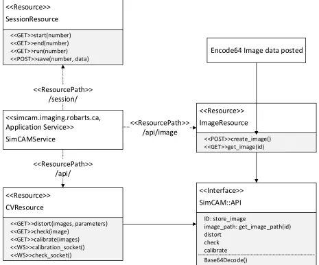
24 <<Interface>> SimCAM::API distort check calibrate <<simcam.imaging.robarts.ca, Application Service>> SimCAMService <<ResourcePath>> /api/ <<Resource>> ImageResource <<POST>>create_image() <<GET>>get_image(id) <<ResourcePath>> /api/image Base64Decode()
Encode64 Image data posted <<Resource>> SessionResource <<ResourcePath>> /session/ <<GET>>start(number) <<GET>>end(number) <<GET>>run(number) <<POST>>save(number, data) ID: store_image image_path: get_image_path(id) <<Resource>> CVResource <<GET>>distort(images, parameters) <<GET>>check(image) <<GET>>calibrate(images) <<WS>>calibration_socket() <<WS>>check_socket()
Figure 2-4: Class diagram describing the REST services implementation for SimCAMService.
Application Initialization
25
the client application are delivered to the WebBrowser, where the session is rendered (triggering the onpageload event). The SimCAM::Router::App JavaScript class is then initialized, which renders appropriate content for the user to see. The SimCAM::Router::App initializes also Views (such as SimCAM::MainView), while binding events from the WebBrowser, that can update the WebBrowser content and URL asynchronously allow for bi-directional interaction with the user.
User :WebBrowser :SimCAMService
Request SimCAM
<<GET>> session
Client Application & session resources rendered view :SimCAM::Router::App onpageload update url SimCAM::MainView bind events
Async. update content <<GET>> simcam(email) Cookie with user session
<<GET>> simcam Home Page Login Form
Submit email
Figure 2-5: Initialization sequence of the client (SimCAM::Router::App) on the WebBrowser. The User triggers the process by requesting the service URL through the WebBrowser. The request triggers the SimCAMService on the server to provide the client application payload, which is then initialized on the WebBrowser when the page is loaded.
Session Resource
26
SessionResource::save requests. The data from the request are store using the SimCAM::Schema as a SimCAM::Schema::Session in the database. Each SimCAM::Schema::User is provided with cookies that are deployed with SessionResource::start responses.
<<Resource>> SessionResource <<GET>>start(number) <<GET>>end(number) <<GET>>run(number) <<POST>>save(number, data) SimCAM::Session start() run() end() <<Interface>> SimCAM::Schema SimCAM::Schema::Usr id email SimCAM::Schema::Session id usr_id start_time end_time milestone json_store
Figure 2-6: Class diagram describing session resource provide by SimCAM::Service.
Image/CV Resource
The image resource (shown in Figure 2-7) is responsible for storing and serving the image and image data resources. The ImageResource accepts a <<POST>> request of base64 [45] (a lossless encoding format) for image data and generates a server version of the image on the file system.The ImageResource then serves the image to <<GET>> requests to the resource URL. The client is
able to construct encode64 image data using the HTML5 canvas tag. The computer vision resource is provided by CVResource on the /api/ URL. The CVResource provides responses to <<GET>>
27
CVResponse also provides sockets for bi-directional data transfer with WebSockets for <<WS>> requests. All computer vision operations are programs that run on the local version of the image (captured from ImageResource). Once these operations are completed the results are stored in a public folder and the paths sent via JSON in responses.
SimCAM_CV
distort( distortion_xml, in_image, out_image, intrinsic_xml)
check(image_path)
calibrate(intrinsics_path, distortions_path, ... )
<<Interface>> SimCAM::API distort check calibrate <<simcam.imaging.robarts.ca, Application Service>> SimCAMService <<ResourcePath>> /api/ <<Resource>> ImageResource <<POST>>create_image() <<GET>>get_image(id) <<ResourcePath>> /api/image Base64Decode() Encode64 Image data posted
ID: store_image image_path: get_image_path(id) <<Resource>> CVResource <<GET>>distort(images, parameters) <<GET>>check(image) <<GET>>calibrate(images) <<WS>>calibration_socket() <<WS>>check_socket()
28
Asynchronous Client/Server data interface
The SimCAM JavaScript application binds directly to resources on the SimCAMService, using
the SimCAM::Model::Generic. SimCAM::Model::Generic is an implementation of
Backbone::Model, where a URL resource can be defined on initialization. Once the client is initialized, the SimCAM::Model::Generic instances can request and update asynchronously with the SimCAMService (via the Backbone::Model shown in Figure 2-8). The advantage of using asynchronous connection is that the frontend client does not have to wait for the response from the
server. Backbone.JS additionally provides a Backbone::Collection class that can be used to implement a collection of models, which are used for the image captures and calibrations taken by the user. <<simcam.imaging.robarts.ca, Application Service>> SimCAMService SimCAM::Model::Generic float: DEG2RAD(degree) float : RAD2DEG(radians)
<<Abstract>> Backbone::Model
fetch()
url : String save()
REST Service connection <<Abstract>> Backbone::Collection SimCAM::Collection::Calibratio ns latest_results() distortions_series_parameter s() SimCAM::Collection::Captures
String url : to_calibrate()
29
Graphical User Interface
SimCAM was designed around a tutorial format, using user stories and feedback to do paper prototyping. Paper prototyping is a technique to quickly design graphical user interfaces [45]. The user logins in with their email address, which allows the system to track and store their results. The user is presented with background materials that guide them through 6 milestones.
1. Determine if the user’s browser supports required technology
2. Teach user about the camera matrix and pose parameters using the pinhole camera model 3. Radial and tangential distortion tutorial and simulator
4. Camera calibration background and simulation environment 5. Web camera calibration simulator
6. Content validity questionnaire
30
31
Another important GUI designed was the 3D workspace environment shown below.
Figure 2-10: Paper prototyping of GUI Design for 3D interactive components. The camera view shows the current camera’s view. The 3D workspace is where the user interacts with the camera and calibration grid. The side menu provides buttons for camera calibration results and capturing images. The captured images are shown in the additional results area. Finally the rotation/position manipulator shows the rotation and position of the current select object that can also be edited.
Since this was a pilot project, most of the design was created during the implementation period. This was accomplished by performing several iterations of implementation periods, where each iteration focused on a feature or specification.
SimCAM::View Classes
The relationship between the SimCAM::View classes, SimCAM::Router and Backbone are shown
32
<<Abstract>> Backbone::View
initialize() render()
SimCAM::Router::App
initialize() events : Hash
<<Abstract>> Backbone::Router SimCAM::View::ObjectRTModal
SimCAM::View::MainWebCamView
SimCAM::View::MainCanvas
SimCAM::View::SideCanvas
SimCAM::View::SideMenu
SimCAM::View::BottomBar
SimCAM::View::ResultsModal
SimCAM::View::MainView
Figure 2-11: Class diagram describing the class hierarchy for views in SimCAM. All
SimCAM::Views are implementations of Backbone::View and initiated by the
SimCAM::Router::App.
SimCAM::View::MainView : The main view is the first view to be initialized by the
33
SimCAM::View::MainCanvas : The 3D workspace and user inputs with the mouse in
those areas are managed by the main canvas view. In the webcam interactive view the main canvas loads the webcam view (SimCAM::View::MainWebCamView).
SimCAM::View::SideCanvas : The camera view element in Figure 2-9is managed by
the SimCAM::View::SideCanvas. This view watches for all changes on the MainCanvas to update the camera view.
SimCAM::View::SideMenu : The side menu view swaps several templates depending on
the parameters passed by SimCAM::Router::App. It shows the various menus for the distortion, calibration and webcam calibration milestones.
SimCAM::View::BottomBar : The bottom bar holds additional results such as the
captured images in the calibration and webcam calibration milestones.
SimCAM::View::ObjectRTModal : The ObjectRTModal shows the position and
rotation of the object currently clicked on in the main canvas.
SimCAM::View::ResultsModal : The results modal shows calibration results, charts and
efficacy.
SimCAM Graphical User Components
SimCAM’s GUI can be broken down by logical sets of features that cover the functional
34
Figure 2-12: Hierarchy of implemented components of SimCAM: Simulation, Interactive,
Feedback, Tutorial Materials and Validation computers
Camera
The camera was implemented using WebGL, which supports perspective cameras that can also be manipulated by users in the interface show in Figure 2-13.
SimCAM Implementation
Simulation
Camera
Distortions
Calibration
Interactive
Camera matrix
Pose
Webcam
Feedback
Efficacy
Calibration parameters
Tutorial Materials
Quizzes
Validation
35
Figure 2-13: 3D interactive camera implementation, with the 3D workspace, camera view and the rotation/translation manipulator.
Controls were implemented in the 3D workspace (blue pyramid) which can be moved and rotated using the mouse. Additional controls are also provided in the bottom right widget where rotation and positions can be typed in. All the manipulations change the camera view in the top right. This is also where distortions are simulated.
Distortions
Distortions were implemented on the server side and powered by the OpenCV library (Figure 2-14). The user would be presented with several controls in the side menu (right) to change the
36
Figure 2-14: Distortion simulation with controls on the side menu where the user can adjust the parameters for radial and tangential distortions.
Image Data Serializing and Communication
Implementation of distortions on SimCAM’s camera required a method to send the 3D data to the
server. Image data were captured from the camera view and serialized (compressed into a text string). The serialized image data were encoded on the client side and sent via WebSockets to the
37
Calibration
In the camera calibration interactive component, the user was provided a random simulated camera with distortions. The camera is presented with a calibration grid (checkerboard pattern). The user is then able to move and position the calibration grid (using either the mouse or the widget), and capturing images by clicking the button labeled A in Figure 2-15. The captured images is validated by checking if the calibration grid is present in them, and shown in the bottom panel (B in Figure 2-15). The valid images are then used to perform a calibration attempt. Once a calibration attempt is done the results button is enabled in the side menu. Clicking this opens the calibration dialog
which provides feedback about the current calibration attempt and compares it to previous calibration attempt. This is described in further detail in the feedback section (Figure 2-19, Figure 2-20, and Figure 2-21).
Figure 2-15: User interaction with calibration environment. (Step 1, A) Capture image with camera. Images appear in (Step 2, B).
Interactive Components
Several embedded components were developed that allowed users to interact and learn about various parameters.
A
B
38
Camera Matrix
The widget shown in Figure 2-16 is embedded in the 2nd milestone of the tutorial and allows users to change the camera matrix in the 3D environment. This widget was implemented by exploiting the OpenGL matrix pipeline. In this pipeline, OpenGL can push matrices that will affect the rendering of the camera view.
Figure 2-16: Camera matrix manipulator widget. Users can change the focal length and principal points of the camera in the 3D environment above.
The widget shown in Figure 2-16 is embedded in the 2nd milestone of the tutorial and allows users to change the camera matrix in the 3D environment. This widget was implemented by exploiting the OpenGL matrix pipeline. In this pipeline, OpenGL can push matrices that will affect the rendering of the camera view.
Camera Pose
With this embedded widget (Figure 2-17) users can see how the camera pose matrix is affect when they move the camera in the environment. Also users can directly change the pose matrix here and
39
Figure 2-17: Camera pose manipulator. The user can adjust the rotation and translation matrix directly to the 3D environment in the same milestone.
Webcam
40
Figure 2-18: Interactive webcam component that allows user to calibrate their web camera. They use their phones or printed paper to display an 8x5 calibration on their web camera. By clicking the capture button similar to the calibration environment in Figure 2-15. The captured images are shown in the bar on the bottom and the calibrated results in the results dialog (Figure 2-19)
Feedback
41
Figure 2-19: Feedback popup dialog which shows the calibration parameters, graphs (Figure 2-20) and efficacy (Figure 2-21) of the current calibration attempts
Efficacy
Difference images of the undistorted image and the corrected image show how well a camera was calibrated. An ideal difference, were the image was perfectly calibrated, would show as a completely black image (no difference). Thus by reviewing the difference image users were provided quick feedback on the efficacy of each of their calibration attempts. These difference
42
Figure 2-20: Example of differencing the corrected and undistorted images. In the simulation environment the undistorted images are simulated camera views before the simulated distortion is applied. The distorted images are with simulated distortions applied, and the corrected images are with the calibration parameters used to correct the distorted image. The final efficacy of the calibration is based on the difference image of corrected and undistorted image.
Charting calibration parameters
The current calibration parameters are available on the first tab of the popup dialog (Figure 2-19) and also as an interactive line graph chart (Figure 2-21). This line graph shows all the calibration parameters for each calibration attempt, and shows how each parameter value eventually
43
Figure 2-21: Example of charted calibration parameters. Clicking on the legend values enables each series
Content Validity
44
Testing & Validation
In SimCAM two types of testing were completed: software testing and content validity. SimCAM’s software was tested with manual integration test cases and automated unit test cases
that tested major views of the system. The user acceptance testing (UAT) was performed in the format of a content validation questionnaire. The content validity study was used to gauge if SimCAM covers the required camera calibration subject, verify design decisions and the explore value of certain features. The questionnaire (Appendix A) has six sections.
The first section captures demographics of the participant
The second section covers questions about specific content in the simulator (discussed in
the implementation section 2.4)
The third section covers yes and no questions that focused on determining if the participant
agreed with the specific direction of SimCAM
The fourth section determines if SimCAM is appropriately difficulty
Finally free form comments are captured
The results of the content validity are discussed in the Results chapter.
Participants
The SimCAM content validity questionnaire targeted both expert and non-expert (who would be
45
Quiz Results
Throughout each milestone users were quizzed with several multiple choice questions reviewing the material just presented. The quizzes were made to be a quick review, to check if the user was able to understand the material. It was expected that the expert users should have a higher score on average than the non-experts, helping to further differentiate the two groups.
Demographics
The content validity study also collected the following demographics, which were used to differentiate the expert user from the non-expert:
1. What is your area of study/program?
2. How many hours have you been awake?
3. What is your experience in number of years with computer vision/graphics?
4. What is your experience in number of years with linear algebra?
5. If you have done camera calibration in the past, about how many different times have you done it?
Questions 1 and 3 to 5 were included to determine the experts in the pool of users. Question 2 was included to exclude unexpectedly bad quiz results, for example, if the user was awake for too long.
Content Validity Questionnaire
On the last milestone, users were given 4 sections (sections A-D) that generated results to validate the content of SimCAM. Section A presented users with 12 questions (Appendix A) and users were asked to respond by circling a number on a 5-point Likert scale where:
1= Strongly Agree
2= Agree
3= Neutral
4= Disagree
46
The Likert scale is a psychometric scale used frequently in studies that are dependent on questionnaires. The scale runs from an extreme to another opposite extreme, with a neutral point in between. This scale is a tool to measure attitudes [47], and used in this study to measure attitudes about the content of SimCAM.
Specific Content Validity Questions
Users were asked the 12 questions to measure the attitudes using the Likert scale:
Questions 1 and 2 covered the motivation of SimCAM. Users were asked if they agreed that having a self-directed and structured tutorial for learning camera calibration is valuable. Question 3 asked
if SimCAM was a good introduction for camera calibration.
Question 4 also asked if SimCAM improved understanding of camera calibration.
Question 5 to question 10 asked participants if the various implemented components listed below were valuable for learning camera calibration.
5. Simulation of pin-hole camera model, camera matrix and pose matrix (Figure 2-13, Figure 2-16, and Figure 2-17)
6. Simulation of the radial and tangential distortions (Figure 2-14)
7. Simulation of the calibration task (Figure 2-15)
8. Feedback provided with the line graphs (Figure 2-21)
9. Feedback provided with difference images (Figure 2-20)
10. Webcam calibration component (Figure 2-18)
Finally, the last two questions asked if participants would continue to use SimCAM and if they would recommend it to beginners.
47
1) Is simulating individual aspects (e.g. rotation matrix, distortion parameters, etc.) of the camera calibration task valuable for training?
2) Is simulation of the overall calibration task in an ideal environment important for camera calibration training?
3) Should software programming using the OpenCV library (used for calibrating images) be included in the tutorial for camera calibration training?
4) Is the amount of simulation you were exposed to in the environment sufficient for an introduction to camera calibration?
The first two questions were included to capture users’ opinions on the motivation behind
SimCAM. Since OpenCV is a commonly used library for camera calibration, question 3 was included to determine if expert users feel a software programming tutorial is needed. Question 4 was presented to determine if user’s felt there was enough fidelity in the simulator.
Section C asked expert users to compare the difficulty of the simulator and a real camera calibration procedure. The difficulty of the simulator should be low enough to allow non-experts an acceptable learning curve, but high enough to represent common challenges in camera calibration.
Section D was used to qualify certain questions in Section A based on if the simulator and web-cam technology worked as expected.
Free form comments were recorded from users, which let them provide additional insight and critique of the content.
Analysis
48
1= Strongly Agree (100%) 2= Agree (75%)
3= Neutral (50%) 4= Disagree (25%)
5= Strongly Disagree (0%)
Once quantified an overall agreement score is generated for the expert and non-expert users. An arbitrary agreement of over 75% was considered as valid content.
Since Section B consisted of Yes/No answers, their statistical mode were used to determine if the experts and non-experts users’ agreed with the question.
49
3
Results
3.1
Introduction
SimCAM was made available online2 and users finished quizzes and the content validity study.
Overall, 13 users who meet the criteria as participants completed the study. The first type of data collected on the participants was the total time spent on the study. Using these data, 2 participants were excluded as they completed the study too quickly, suggesting they did not read the tutorial materials. There were more non-experts (7) than experts (4) in this study. The remaining participants were then separated into groups of experts and non-experts. This determination was made based on the captured demographics information. Results of the remaining content validity questionnaire (See Appendix A) were also recorded. The statistical analysis of results of each section are presented below. Finally the result of each quiz in the milestones of the tutorial was also available.
3.2
Time Spent on Tutorial
The overall time spent was calculated as a sum of the time spent on each milestone in the tutorial. The time spent data indicates the presence of outliers as the mean was 51.4 minutes with a standard deviation of 58 minutes. Reviewing the results was helpful in eliminating 2 participants that had simply skimmed the study as indicated by their extremely low (compared to the mean) time spent (2 and 4 minutes) on the tutorial. The excluded participants also selected the same answer for each multiple choice question and had nonsensical answers for written answers.
3.3
Content Validity
The content validity results were based on Section A of the questionnaire. The experts and non-experts (Figure 3-1) both validated that the content of SimCAM was appropriate and valid for
2
50
teaching camera calibration. Experts had an average of 74.6% (17.5% STD) agreement with Section A questions that the content was valid. Non-experts had an average of 85.7% (9% STD) agreement that the content was valid.
Figure 3-1: Overallcontent validity score between Experts vs. Non-experts. The results indicate that SimCAM has valid content to be a training environment for beginners
3.3.1 Section A: Specific content validity questions
Due to the small number of participants, the possibility of a skewed dataset is high. The outliers in the dataset may result in a misleading standard deviation and standard error of the mean. In a similar study the median and mean were compared to determine an absence or presence of outliers [48].
0.25 0.5 0.75 1
Experts Non-experts
Av
era
ge
Agre
em
en
t
(0
-1)
![Figure 1-3: Depiction of a pinhole camera in the perspective projection model [14] that projects](https://thumb-us.123doks.com/thumbv2/123dok_us/7793934.1292416/19.612.172.441.345.566/figure-depiction-pinhole-camera-perspective-projection-model-projects.webp)