The CMS Event-Builder System for LHC Run 3 (2021-23)
Jean-MarcAndré5, UlfBehrens1,JamesBranson4, PhilippBrummer2,11, SergioCittolin4, Diego Da Silva Gomes2, Georgiana-Lavinia Darlea6, Christian Deldicque2, Zeynep Demiragli6,MarcDobson2,NicolasDoualot5,SamimErhan3,JonathanFulcher2,Dominique Gigi2,MaciejGładki2,FrankGlege2,GuillelmoGomez-Ceballos6,JeroenHegeman2, An-dré Holzner4, Michael Lettrich2, Audrius Meˇcionis5,9, Frans Meijers2, Emilio Meschi2, Remigius K Mommsen5,∗, Sre´cko Morovi´c5, Vivian O’Dell5, Luciano Orsini2, Ioannis Papakrivopoulos7,ChristophPaus6,AndreaPetrucci8,MarcoPieri4,DinyarRabady2,Attila Rácz2,ValdasRapševiˇcius5,9,ThomasReis2,HannesSakulin2,ChristophSchwick2,Dainius Šimeleviˇcius2,9, MantasStankeviˇcius5,9, CristinaVazquez Velez2,Christian Wernet2, and PetrZejdl5,10
1DESY, Hamburg, Germany 2CERN, Geneva, Switzerland
3University of California, Los Angeles, Los Angeles, California, USA 4University of California, San Diego, San Diego, California, USA 5FNAL, Batavia, Illinois, USA
6Massachusetts Institute of Technology, Cambridge, Massachusetts, USA 7Technical University of Athens, Athens, Greece
8Rice University, Houston, Texas, USA 9Also at Vilnius University, Vilnius, Lithuania 10Also at CERN, Geneva, Switzerland
11Also at Karlsruhe Institute of Technology, Karlsruhe, Germany
Abstract.The data acquisition system (DAQ) of the CMS experiment at the CERN Large Hadron Collider (LHC) assembles events of 2 MB at a rate of 100 kHz. The event builder collects event fragments from about 750 sources and assembles them into complete events which are then handed to the High-Level Trigger (HLT) processes running on O(1000) computers. The aging event-building hardware will be replaced during the long shutdown 2 of the LHC taking place in 2019/20. The future data networks will be based on 100 Gb/s
interconnects using Ethernet and Infiniband technologies. More powerful com-puters may allow to combine the currently separate functionality of the readout and builder units into a single I/O processor handling simultaneously 100 Gb/s
of input and output traffic. It might be beneficial to preprocess data
originat-ing from specific detector parts or regions before handloriginat-ing it to generic HLT processors. Therefore, we will investigate how specialized coprocessors, e.g. GPUs, could be integrated into the event builder. We will present the envisioned changes to the event-builder compared to today’s system. Initial measurements of the performance of the data networks under the event-building traffic
pat-tern will be shown. Implications of a folded network architecture for the event building and corresponding changes to the software implementation will be dis-cussed.
1 Introduction
The Compact Muon Solenoid (CMS) experiment at CERN is one of the two general purpose experiments located at the LHC. CMS is designed to study both proton-proton and heavy ion collisions at the TeV scale [1]. The detector comprises about 55 million readout channels. The online event-selection is performed using two trigger levels: a hardware-based first-level (L1) trigger accepting up to 100 kHz of events and a software-based High-Level Trigger (HLT) selectingO(1%) of these events.
The Run-2 event-builder system [2] collects event fragments from about 750 detector backend boards (FEDs) at the L1 trigger rate. It transports the fragments over about 200 m to the surface using a simplified TCP/IP protocol [3] over 10 and 40 Gb/s Ethernet to a
pre-defined Readout Unit (RU) computer. The RU splits the streams into event fragments, checks the consistency and buffers them until it receives the assignment message from the event
manager (EVM). Once the RU knows which Builder Unit (BU) machine has been assigned to handle the event, the RU combines all fragments belonging to the same event into a super-fragment. Each RU waits until it has received the fragments from all FEDs allocated to it before creating the super-fragment. The super-fragment is sent over the event-builder switch to the BUs. The event-builder switch uses Infiniband [4] FDR at 56 Gbit/s. The BU assembles
the super-fragments into complete events and writes them to a local RAMdisk from where they are picked up by the file-base filter farm [5].
2 The DAQ System for LHC Run 3
The LHC undergoes a 2-year maintenance period during 2019/20, followed by another 3
years of running. The conditions for the next running period (Run 3) will be similar to Run 2. There will be a few modifications to the CMS detector which results an a slight increase in the number of readout channels and event size. However, the commercial equipment of the current DAQ system reaches end-of-life after 5 years and needs to be replaced. We will use this opportunity to keep abreast with technological evolution, and explore solutions for the next generation DAQ system [6, 7] needed for the high-luminosity LHC [8] planned for 2025. Novel solutions to be looked at are the combination of the currently separate readout and builder units into a single I/O processor, an architecture known as ‘folded.’ The integration
of co-processors (GPUs and/or FPGAs) into the event building to pre-process events before
handing them to the HLT and partial event acquisition at the bunch-crossing rate of 40 MHz are further topics which will be looked into.
The main enabler for smaller and more efficient DAQ systems are network interconnects.
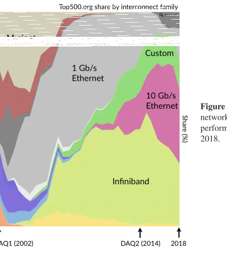
Figure 1 shows the evolution of the market share of network interconnects used in the 500 most performing super-computers. The DAQ system for Run 1 [9, 10] conceived in 2002 used two 2 Gb/s Myrinet links between the backend electronics and the RU, and several 1 Gb/s
Ethernet connections between the RU and BU. It required 640 RUs to handle 1 MB events at 100 kHz trigger rate. The event building was organized into 8 separate readout slices each providing a throughput of about 12.5 GB/s. The events were assigned to the slices in a
round-robin scheme. The Run-2 DAQ system built in 2014 replaced Myrinet with 10 and 40 Gb/s
Ethernet and uses Infiniband FDR (56 Gb/s) as the event-builder network. This allowed to
shrink the size of the system by an order of magnitude, while providing twice the throughput required to handle event sizes of up to 2 MB at 100 kHz trigger rate. The DAQ system for Run 3 continues to use Ethernet and Infiniband, but exploits the faster Ethernet and Infiniband link speeds of 100 Gb/s easily available today. The main change will be the combination of
1 Introduction
The Compact Muon Solenoid (CMS) experiment at CERN is one of the two general purpose experiments located at the LHC. CMS is designed to study both proton-proton and heavy ion collisions at the TeV scale [1]. The detector comprises about 55 million readout channels. The online event-selection is performed using two trigger levels: a hardware-based first-level (L1) trigger accepting up to 100 kHz of events and a software-based High-Level Trigger (HLT) selectingO(1%) of these events.
The Run-2 event-builder system [2] collects event fragments from about 750 detector backend boards (FEDs) at the L1 trigger rate. It transports the fragments over about 200 m to the surface using a simplified TCP/IP protocol [3] over 10 and 40 Gb/s Ethernet to a pre-defined Readout Unit (RU) computer. The RU splits the streams into event fragments, checks the consistency and buffers them until it receives the assignment message from the event manager (EVM). Once the RU knows which Builder Unit (BU) machine has been assigned to handle the event, the RU combines all fragments belonging to the same event into a super-fragment. Each RU waits until it has received the fragments from all FEDs allocated to it before creating the super-fragment. The super-fragment is sent over the event-builder switch to the BUs. The event-builder switch uses Infiniband [4] FDR at 56 Gbit/s. The BU assembles the super-fragments into complete events and writes them to a local RAMdisk from where they are picked up by the file-base filter farm [5].
2 The DAQ System for LHC Run 3
The LHC undergoes a 2-year maintenance period during 2019/20, followed by another 3
years of running. The conditions for the next running period (Run 3) will be similar to Run 2. There will be a few modifications to the CMS detector which results an a slight increase in the number of readout channels and event size. However, the commercial equipment of the current DAQ system reaches end-of-life after 5 years and needs to be replaced. We will use this opportunity to keep abreast with technological evolution, and explore solutions for the next generation DAQ system [6, 7] needed for the high-luminosity LHC [8] planned for 2025. Novel solutions to be looked at are the combination of the currently separate readout and builder units into a single I/O processor, an architecture known as ‘folded.’ The integration of co-processors (GPUs and/or FPGAs) into the event building to pre-process events before handing them to the HLT and partial event acquisition at the bunch-crossing rate of 40 MHz are further topics which will be looked into.
The main enabler for smaller and more efficient DAQ systems are network interconnects. Figure 1 shows the evolution of the market share of network interconnects used in the 500 most performing super-computers. The DAQ system for Run 1 [9, 10] conceived in 2002 used two 2 Gb/s Myrinet links between the backend electronics and the RU, and several 1 Gb/s Ethernet connections between the RU and BU. It required 640 RUs to handle 1 MB events at 100 kHz trigger rate. The event building was organized into 8 separate readout slices each providing a throughput of about 12.5 GB/s. The events were assigned to the slices in a
round-robin scheme. The Run-2 DAQ system built in 2014 replaced Myrinet with 10 and 40 Gb/s
Ethernet and uses Infiniband FDR (56 Gb/s) as the event-builder network. This allowed to shrink the size of the system by an order of magnitude, while providing twice the throughput required to handle event sizes of up to 2 MB at 100 kHz trigger rate. The DAQ system for Run 3 continues to use Ethernet and Infiniband, but exploits the faster Ethernet and Infiniband link speeds of 100 Gb/s easily available today. The main change will be the combination of the functionality of the readout and builder units into a single machine as described in the next section. The DAQ system for Run 3 will be used to gain experience with this architecture
Figure 1.Evolution of market share of network interconnects used in the 500 most performing super-computers from 2000 to 2018.
which is needed for the high-luminosity LHC, where the DAQ system will need to handle 5.5 TB/s using about 500 I/O nodes. The event size at high-luminosity LHC will increase to about 7.4 MB and the trigger rate goes up to 750 kHz.
3 Folded Event-Builder Architecture
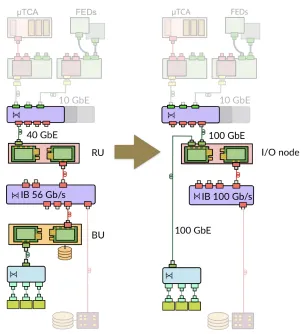
Figure 2 shows a simplified schematic of the current DAQ system and of a possible folded configuration. The readout from the detector backends remains unchanged. It will still be based on the same custom electronics boards sending the data over 10 Gb/s TCP/IP streams. These streams will be concentrated into 100 Gb/s instead of 40 Gb/s Ethernet links to the Readout Units (RUs). The functionality of the fragment buffering on the RUs and the full event building in the Builder Units (BUs) will be collapsed into I/O nodes. These nodes are interconnected by EDR Infiniband at 100 Gb/s. The HLT nodes will share the 100 Gb/s Ethernet network interface cards to access the fully built events. The folded architecture allows to exploit the bi-directional bandwidth of the network links. It requires about half the number of machines and switch ports, which reduces the cost of the system. This is especially important for the DAQ system to be built for the high-luminosity LHC, which will need to handle a 30 times higher throughput. The main challenge of a folded architecture is the demanding I/O and memory performance of the I/O node. It has to process TCP/IP streams at 100 Gb/s, distribute the event fragments to other builder units at 100 kHz, build complete events at 1-2 kHz using fragments received from all other nodes, and make the complete events available to the HLT processors. In addition, it may also need to hand events to co-processors and receive the results of the calculations.
Figure 2. A simplified schematic of the current DAQ system (left) and a possible folded scheme for the DAQ system for Run 3 (right). The main change will be that the Readout Unit (RU) and the Builder Unit (BU) executables will no longer be deployed on separate machines but on a common I/O node.
upon industrial standards, open protocols and libraries. It provides services for data transport, configuration, monitoring, and error reporting. In particular, it also provides a zero-copy architecture for Infiniband [12]. The flexible configuration scheme provided by the XDAQ framework allows to combine the RU and BU functionality without any software change. Only the NUMA settings were re-tuned for the folded configuration to optimize the pinning to CPU cores and memory allocation.
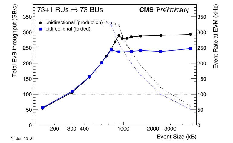
The RU and BU nodes of the Run-2 production system are Dell R620 and R720 dual 8-core sandy bridge @ 2.6 GHz, respectively. They are interconnected with a Clos-network structure with 12 leaf and 6 spine switches (Mellanox SX6036), providing 216 external ports and 12 Tbit/s bi-sectional bandwidth. For this test, event fragments are generated on the read-out unit, i.e. they are not received from TCP/IP streams. Fully built events are discarded on the builder unit instead of being written out. We measured the throughput using a production-like setup where 73 RUs send the data to 73 BUs, and the folded architecture were the BU is running on the same node as the RU. Figure 3 shows that the plateau throughput of the folded architecture is reduced by∼15% compared to the standard unidirectional configuration. The
200 300 400 1000 2000 3000
Event Size (kB)
0 50 100 150 200 250 300 350
Total EvB throughput (GB/s)
21 Jun 2018
0 50 100 150 200 250 300 350
Event Rate at EVM (kHz)
CMS Preliminary
73 BUs
⇒
73+1 RUs 73 BUs
⇒
73+1 RUs
unidirectional (production) bidirectional (folded)
Figure 3. Performance measurement of the event-builder system using the current production system for the standard unidirectional traffic, and for a folded (bidirectional) configuration. The thick lines show the total event-building throughput as function of the event size (left axis). The dashed lines show the equivalent trigger rate in kHz (right axis). The point where they go below the requirement of 100 kHz (dotted line) indicates the maximum event size which can be handled.
folded configuration suffers from the additional I/O requirements and from the large number of threads, which exceed the CPU core count of the legacy hardware. Nevertheless, 2 MB events could still be built at 100 kHz L1 trigger rate.
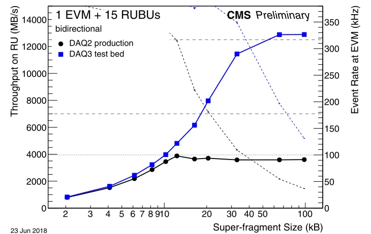
The folded architecture was also tested on a small-scale test system which is based on state-of-the-art hardware with 16 Dell R740 dual 16-cores skylake @ 2.1/2.6 GHz. They are interconnected with a single Mellanox MSB7800 EDR switch (100 Gb/s). Figure 4 shows that an up to 3 times higher throughput is achievable compared to current production hardware using a single leaf switch of the Clos network. Preliminary measurements where the BU writes the data to a RAM-disk show that the disk-writing limits the throughput per BU to 5.5 GB/s. Therefore, the distributions of events to the HLT needs to be improved in order to make use of the higher throughput achievable when building events only.
4 Event Building with MPI
2 3 4 5 6 7 8 910 20 30 40 50 100
Super-fragment Size (kB)
0 2000 4000 6000 8000 10000 12000 14000
Throughput on RU (MB/s)
23 Jun 2018
0 50 100 150 200 250 300 350
Event Rate at EVM (kHz)
CMS Preliminary
1 EVM + 15 RUBUs
bidirectional
1 EVM + 15 RUBUs
bidirectional DAQ2 production DAQ3 test bed
Figure 4. Measurement of a folded event-builder architecture with 15 nodes using the current pro-duction hardware (Run 2), and state-of-the-art hardware installed in a test bed for the next generation DAQ system for Run 3. The thick lines show the throughput on the Readout Unit (RU) as function of the super-fragment size generated on the RU. The dashed lines show the equivalent trigger rate in kHz (right axis).
The API defines communication operations suitable for a large variety of use cases, that can be separated into three groups. Point-to-point communication allows to exchange data between two processes using explicit send and receive operations. Collective communication procedures implement data exchange patterns along a group of processes. One-sided commu-nication also referred to as Remote Memory Access (RMA) allows direct access of memory previously exposed by another process.
In the end only MPI point-to-point communication procedures provided the necessary flexibility and fault tolerance. The collective procedures proved to be inflexible when dealing with non-uniform fragment sizes and error handling. One-sided procedures, which decouple the exchange of data from synchronization, could not be mapped to the problem of event building efficiently.
The performance of MPI and Infiniband Verbs used by XDAQ has been evaluated using a benchmark, that simulates two stage event building traffic without building the actual events.
Highest throughput was reached using a zero-copy queuing algorithm based on MPI point-to-point communication. MPI Runtime parameters enforced data locality between commu-nication processes and Infiniband hardware and network transport was delegated by the MPI API to the vendor tuned UCX [15] framework. Despite our efforts, only a slightly higher
performance than with Infiniband Verbs was achieved (see Figure 5). The marginal perfor-mance gain, combined with limited fault tolerance and large tuning efforts for MPI, leads to
the conclusion that as of now, the MPI API does not map onto the task of event building at the CMS experiment.
2 3 4 5 6 7 8 910 20 30 40 50 100
Super-fragment Size (kB)
0 1000 2000 3000 4000 5000
Throughput on RU (MB/s)
21 Jun 2018
0 50 100 150 200 250 300 350
Event Rate at EVM (kHz)
CMS Preliminary
64 BUs
⇒
64 RUs
unidirectional64 BUs
⇒
64 RUs
unidirectional EvB MPIFigure 5.Comparison of the throughput of the full buidler software (EvB) with a simple event-builder benchmark based on MPI point-to-point communication. The MPI benchmark shows a better performance for small super-fragment sizes, but does not achieve a significant improvement for larger sizes.
5 Integration of Co-Processors
The integration of general-purpose GPUs and/or FPGAs into the reconstruction of events
might be a cost-effective solution to reduce the required CPU power on the High-Level
Trig-ger (HLT). This will become a real issue on the time scale of the high-luminosity LHC. Equipping each HLT node with a GPU could not be cost effective. The GPU cannot be fully
loaded unless the majority of the event reconstruction and selection can be done on the GPU. In addition, the life cycle of the GPU and host computer might be different, which
compli-cates any hardware upgrades.
A solution would be to offload specific parts of the event reconstruction to a farm of
GPU-equipped nodes during the HLT processing. However, this requires a mechanism and network to transfer data to and from a GPU farm. This adds latency for data transport and careful tuning will be needed to avoid that the HLT CPUs stall on network transfers.
Another option would be to pre-process all events at the event-builder level before hand-ing them to the HLT farm. This avoids any latency durhand-ing the HLT processhand-ing and is tech-nically easier to solve. It could be an effective solution for specific tasks on a subset of the
event data, e.g. to reconstruct tracks in the pixel detector. However, such an approach would waste many GPU cycles if the result from the calculation is only used for a small number of events.
6 Summary
The requirements of the DAQ system for the LHC Run 3 in 2021-23 do not change signifi-cantly. However, the commercial components of the current DAQ system reach their end of life after more than 5 years. Therefore, a new DAQ system needs to be built in 2020. It will make use of 100 Gb/s Ethernet and Infiniband networks, as well as more powerful PCs.
The DAQ system for Run 3 will be used to gain experience with techniques needed for the much more performant DAQ system needed for high-luminosity LHC. An interesting option is the use of a folded architecture, which would better exploit the hardware capabilities. Results from initial measurements using the Run-2 production system and a testbed featuring state-of-the-art hardware look promising. However, handling a 100 Gb/s TCP/IP stream on
the PC in addition to the full event-building traffic will be challenging. Special attention is
needed to find an efficient working point in terms of fragment sizes. In addition, the data
distribution to the HLT farm needs to be improved in order to be able to shrink the size of the DAQ system.
We plan to investigate how GPU and/or FPGAs could be integrated into the online event
reconstruction either at the event-builder level or during the HLT processing. Investigations into using MPI for the event building did not show any clear benefit over the current verbs-based implementation. However, MPI could be an option to ease the integration of GPUs into the event building.
Acknowledgments
This work was supported in part by the DOE and NSF (USA).
References
[1] CMS Collaboration, JINST3, S08004 (2008)
[2] R.K. Mommsen et al., J. Phys. Conf. Ser.898, 032020 (2017) [3] P. Zejdl et al., J. Phys. Conf. Ser.513, 012042 (2014)
[4] InfiniBand Trade Association, see http://www.infinibandta.com
[5] E. Meschi et al., J. Phys. Conf. Ser.664, 082033 (2015) [6] E. Meschi et al., J. Phys. Conf. Ser.898, 032019 (2017) [7] J. Hegeman et al. (2018),arXiv 1806.08975
[8] G. Apollinari, I. Béjar Alonso, O. Brüning, P. Fessia, M. Lamont, L. Rossi, L. Tavian, High-Luminosity Large Hadron Collider (HL-LHC): Technical Design Report V. 0.1, CERN Yellow Reports: Monographs (CERN, Geneva, 2017),http://cds.cern.ch/ record/2284929
[9] G. Bauer et al., IEEE Trans. Nucl. Sci.55, 198 (2008) [10] R.K. Mommsen et al., J. Phys. Conf. Ser.219, 022038 (2010) [11] J. Gutleber et al., J. Phys. Conf. Ser.219, 022011 (2010) [12] A. Petrucci et al., IEEE Trans. Nucl. Sci.60, 4595 (2013)
[13] M. Lettrich, Master’s thesis, CERN and Technical University of Munich (2018), https://mediatum.ub.tum.de/1482023
[14] Message Passing Interface Forum,MPI: A Message-Passing Interface Standard, Version 3.1(High Performance Computing Center Stuttgart (HLRS), 2015)