Volume 2008, Article ID 342141,13pages doi:10.1155/2008/342141
Research Article
Power-Efficient Communication Protocol for
Integrated WWAN and WLAN
SuKyoung Lee,1WonSik Chung,1KunHo Hong,1and Nada Golmie2
1Department of Computer Science, Engineering College, Yonsei University, Seoul 120-749, South Korea 2National Institute of Standards and Technology, Gaithersburg, MD 20899, USA
Correspondence should be addressed to SuKyoung Lee,[email protected]
Received 27 February 2007; Revised 27 August 2007; Accepted 31 October 2007 Recommended by Kameswara Rao Namuduri
One of the most impending requirements to support a seamless communication environment in heterogeneous wireless networks comes from the limited power supply of small-size and low-cost mobile terminals as in stand-alone WLANs or cellular networks. Thus, it is a challenge to design new techniques so that mobile terminals are able to not only maintain their active connection as
they move across different types of wireless networks, but also minimize their power consumption. There have been several efforts
aimed at having mobile devices equipped with multiple interfaces connect optimally to the access network that minimizes their power consumption. However, a study of existing schemes for WLAN notes that in the idle state, a device with both a WLAN and a
WWAN interface needs to keep both interfacesonin order to receive periodic beacon messages from the access point (AP: WLAN)
and downlink control information from the base station (WWAN), resulting in significant power consumption. Therefore, in this
paper, we propose a power-efficient communication protocol (PCP) that includes turning offthe WLAN interface after it enters
the idle state and using the paging channel of WWAN in order to wake up the WLAN interface when there is incoming long-lived multimedia data. This scheme is known to limit the power consumption, while at the same time, it makes use of the paging
channel in cellular networks. Further, our proposed scheme is designed to avoid repeatedly turning on and offWLAN interfaces,
that consumes a significant amount of power. We propose turning on the WLAN interface when the number of packets in the
radio network controller (RNC)’s buffer reaches a certain threshold level. The tradeoffs between the power saving and the number
of packets dropped at the buffer are investigated analytically through the study of an on/offtraffic model. Simulation results for
scenarios of interest are also provided.
Copyright © 2008 SuKyoung Lee et al. This is an open access article distributed under the Creative Commons Attribution License, which permits unrestricted use, distribution, and reproduction in any medium, provided the original work is properly cited.
1. INTRODUCTION
The current trends towards achieving a ubiquitous comput-ing environment require the integration of a variety of cur-rent and future wireless networking technologies to support seamless communication for multimedia applications. More specifically, a significant number of telecommunication car-riers are migrating towards heterogeneous wireless networks, where wireless local area networks (WLANs) based on IEEE 802.11 standards and third-generation wireless wide area networks (3G WWANs) such as CDMA2000 and universal mobile telecommunications system (UMTS) are intercon-nected in order to offer Internet access to end users with better quality of service (QoS). These trends are set by the well-known fact that the two technologies have characteris-tics that complement each other perfectly. However, before
a cost-effective and seamless integration of heterogeneous wireless networks is realized, a number of issues have to be resolved. There are several research and standards group ac-tivities including the recently formed IEEE 802.21 Working Group focused on this integration of networks [1].
dual-mode) interfaces, switching their connection to the ac-cess network that provides the best coverage. The authors of [2] introduced several performance metrics that can be used in the handover decision. In [3], the authors propose an end-to-end mobility management system that reduces unneces-sary handover and ping-pong effects by obtaining and ana-lyzing the conditions in different networks. In addition, vari-ous network layer-based inter-network handover techniques are evaluated for a realistic heterogeneous network testbed in [4]. As for a potential integration architecture for WLAN and 3G WWAN, the authors of [5] describe a loosely cou-pled architecture in the form of an IEEE 802.11 gateway and a corresponding service access client software. Most recently, a global-positioning-system- (GPS) based location-aware ver-tical handover scheme is introduced in [6], while in [7], an architecture of a vertical handover scheme based on the pag-ing channel (PCH) of cellular networks is proposed.
Here, it is worth mentioning that a large portion of the power consumption in a wireless interface corresponds to the power consumed while the interface is idle, denoted by idle power. In most existing vertical handover management schemes [2–4], a mobile node must turn on both WLAN and WWAN interfaces even in the idle state with the power save mode, in time to receive the periodic beacon signals from the AP and the signal through the downlink control chan-nels (pilot, sync, or paging channel) from the base station (BS), resulting in significant power consumption.
Therefore, in this paper, we propose a power-efficient communication protocol (PCP) for heterogeneous wireless networks, that is, an extension to the PCH-based vertical handover scheme proposed in [7]. This scheme assumes that if a certain time expires just after the WLAN interface enters the idle state, regardless of whether the power save mode is used, the interface is turned offwithout any periodic wake-up. In the remainder of this paper, this state will be referred to as theinactive state. In addition, we use the PCH in cellu-lar networks in order to turn on the WLAN interface due to incoming data from long-lived multimedia traffic. Our goal is to keep the WLAN interface, which consumes a significant amount of power in the idle mode, offfor a longer period of time. Therefore, we propose using the relatively lower-power PCH in order to wake up the WLAN interface on an as-needed basis. Thus by utilizing the PCH to learn about the presence of incoming data, a mobile device can signifi-cantly reduce its power consumption since it does not have to continuously scan the beacon signals. If the WLAN interface spends considerable amount of time in the idle state, as in the case of Internet access and long multimedia downloads, there are obvious benefits for limiting the power consumption and entering the inactive state [8,9]. In fact, it is reported in [9] that this scenario can result in up to 98% of battery power savings. In addition, we observe that this inactive state fur-ther reduces the power consumed by an AP since it is largely dependent on the power consumed by all the powered-on nodes that it is supporting.
Further, our proposed scheme is designed to avoid re-peatedly turning on and offWLAN interfaces, which con-sumes a significant amount of power. We propose turning on the WLAN interface when the number of packets in the radio
network controller (RNC)’s buffer reaches a certain thresh-old level.
The remainder of this article is structured as follows. Section 2discusses the proposed PCP protocol in greater de-tail.Section 3provides an analysis of the power consumption during the non-communication state for a typical WLAN node, as well as the proposed PCP.Section 4provides sim-ulation results and a discussion of the results. Conclusions are offered inSection 5.
2. POWER-EFFICIENT COMMUNICATION PROTOCOL
In this section, we describe our power-efficient communica-tion protocol (PCP) for heterogeneous wireless networking system. In the following, we first describe the system model assumed before presenting how the PCP works.
2.1. System model
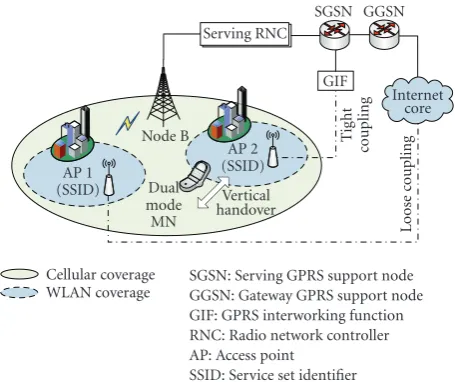
AP 1
SGSN: Serving GPRS support node GGSN: Gateway GPRS support node GIF: GPRS interworking function RNC: Radio network controller AP: Access point
SSID: Service set identifier
Figure 1: Architecture of an integrated heterogeneous network consisting of WWAN and WLAN.
Table1: Typical power consumption for WLAN and WWAN inter-faces.
Interface Power consumption (watt)
Idle Uplink Downlink
WWAN (CDMA: GTRAN) 0.082 2.8 0.495
WLAN 1.04 (PS on) 6.96 7.28
(Cisco Aironet 5 GHz) 1.59 (PS off) — —
detailed standards about how to establish a roaming agree-ment and transfer the information among multiple operators for seamless handover [12,13].
Our system model is based on the generic architecture for integration of WWAN and WLAN defined in [4,14]. In this architecture, the WLAN is connected to the SGSN via the GPRS interworking function (GIF), which provides a stan-dardized interface to the GPRS core network and virtually hides the WLAN peculiarities. The primary function of the GIF is to make the SGSN consider the WLAN as a typical GPRS access system. In the system, the mobile node utilizes packet data protocol (PDP) to manage its ongoing sessions. When the mobile node is just turned on or enters the hetero-geneous wireless networking system, a PDP address (usually an IP address) is allocated to the mobile node by a dynamic host configuration protocol (DHCP) server for IP connec-tion. The PDP context can be maintained in the tightly cou-pled case as shown inFigure 1when the mobile node changes an access technology. Thus when a vertical handover occurs, the packets destined to the mobile node can be rerouted at the SGSN by using the intra/inter SGSN routing area update (RAU) procedure defined in [14] without going through the reauthentication process.
2.2. The proposed PCP scheme
When connected to the WLAN, a WLAN interface card is usually in the idle mode for around 70% of the overall time
including the time during which the interface is turned off [15]. Typically, as long as the WLAN interface is turned on (even in the idle state with power save mode), it will wake up periodically in time to receive beacon signals from the AP regarding any traffic activity on the link.Table 1shows the power consumption for typical WWAN and WLAN inter-face cards [16–19]. It is noteworthy to point out that in the idle state, the power consumption level of a WLAN interface can be significant. Moreover, the power consumption level for a WLAN interface is about 13 and 19 times greater than a WWAN interface, with and without power saving (PS), re-spectively (shown inTable 1).
Each cell in a WWAN may contain more than one WLAN hot spot because the service area of a BS is generally larger than that of a WLAN hot spot. Thus in the idle state, the WWAN interface is assumed to listen continuously to the PCH to detect messages directed to APs in its cell in addi-tion to the messages addressed to it. This assumpaddi-tion is valid since the WWAN interface has to support the operation of frequent traffic (e.g., MMS: multimedia messaging service) compared with data traffic in WLAN.
Our proposed PCP scheme aims at limiting the WLAN power consumption, where the WLAN interface is made to consume power only when transmitting or receiving data. This is accomplished by turning off the WLAN interface without any periodic wake-up during the idle period, which we call inactive state in this paper as shown in Figure 2. Herein, the PCP scheme modifies the WLAN interface state machine as follows:
(i) Communication state: A WLAN interface sends or/ and receives data.
(ii) Non-communication state: A WLAN interface goes to this state when the data session is completed. (Typical WLAN: idle state; PCP: inactive state).
Figure 2gives the detailed procedures that are executed by the WLAN interface in both states described above. Note that we only show the procedures that need to be imple-mented in support of PCP. These procedures are as follows.
(1) Registration of AP in WWAN
AP 1 APM
Node IF Node IF Node IF WLAN IF is turned offwithout periodic wake up
∗Paging: on behalf of beacon signal
(a) Inactive state of WLAN interface under PCP
Data traffic Control message
AP 1 APM
Node IF Node IF Node IF Turn on WLAN IF
Incoming WLAN IF is turned on
via paging from BS Download data via WLAN IF Download data
via WWAN IF
∗Paging: notify than WLAN interface should be turned on
(b) Communication state of WLAN interface under PCP Figure2: Overall architecture of PCP without periodic wake-up beacons (a) when the WLAN interface is in the inactive state, with the APs registered with the GIF, and (b) when the WLAN interface is in the communication state and is ready to receive incoming data from AP 1.
to itself and correctly route the data to the correct mobile nodes.
(2) Interface selection procedure for uplink traffic in inactive state
Once the transmission queue on the wireless link is filled with data packets, the WLAN interface enters the communi-cation state and starts transmitting data. This procedure can be further divided into three substeps as follows.
Step 1. When the WLAN transmission queue contains a
packet, the WLAN interface enters the communication state.
Step 2. The mobile node searches for all APs in its area. It associates with the AP that has the highest received signal strength (RSS). If no APs are found, data transmission is per-formed through the WWAN interface.
Step 3. The mobile node transmits the buffered data to the AP it is associated with during Step2.
(3) Interface selection procedure for downlink traffic in inactive state
In a 3GPP system, the RNC is responsible for controlling user traffic between a user and the core network with buffers for different users. In other words, it is responsible for manag-ing the resources of one or more radio base stations [20,21]. Our PCP scheme uses a similar approach. Thus for down-link transmission, the BS notifies the mobile node when the number of packets in a per-user-buffer at the RNC [20–23] reaches a certain thresholdn(usually less than the maximum buffer size) so that the mobile node does not consume its power due to frequent turn-on and offactions. The steps of our mechanism for signaling the presence of downlink data are illustrated inFigure 3and include the following steps.
Step 1. For downlink transmission, data traffic comes into a per-user-buffer at the RNC when mobile node WLAN inter-face is in the inactive state. Once the number of packets in the buffer reaches a thresholdn, the BS notifies the mobile node about the existence of downlink data by its periodic paging message including PAGING DT=true via its PCH.
Step 2. Upon receiving the notification, the WLAN inter-face is turned on and an available AP is found. If no APs are found, the data transmission is performed through the WWAN interface.
Step 3. Once the mobile node associates with the AP that has the highest RSS, it sends an RAU request message to the related GIF while receiving the incoming data through the WWAN interface.
Step 4. Upon receiving the RAU request message, the GIF forwards the RAU request message which contains the SSID and MAC address of the AP selected for the mobile node to the corresponding SGSN.
Step 5. Once the SGSN receives the RAU request message, it responds to the mobile node by sending an RAU accept mes-sage and switches the route for the data, destined to the mo-bile node, to the corresponding GIF. Then, the SGSN sends the incoming data to the GIF. However, the remaining pack-ets in the RNC buffer are transmitted to the mobile node through the WWAN interface, if there still remain any.
Step 6. The GIF transmits the data received from the SGSN to the mobile node.
Get beacon (RSS, SSID, MAC addr.) from APs
Registration (SSID, MAC addr.) of APs
Forward the incoming data to AP through GIF RSS of target AP> s?
Yes Yes
No
RAU request RAU request
RAU accept
RAU accept Data incoming
PAGING DT=false
PAGING DT=true No. of packets
in buffer> n?
Send the incoming data Inactive state of WLAN interface
Active state of WLAN interface Download data
via WWAN while buffering
data at RNC
Download data via WLAN
WLAN interface is turned on
SGSN/PCF RNC/BS MN AP GIF
-DT: Downlink traffic; s: Threshold of received signal strength (RSS)
Figure3: Signaling procedure when WLAN interface goes from the inactive to communication state to receive downlink traffic.
Activate PDP context
If (n≤no. of packets in buffer), PAGING DT=true (WLAN on) Node IF
Routing area update (RAU) from the MN for
re-routing at the SGSN
RNC
BS SGSN GGSN
GIF
1
2 3
PDP context PDP
context
4
Threshold valuen
is set based on the QoS profile Mobile node
WWAN IF WLAN IF
Figure4: Schematic procedure of setting the threshold,nin our PCP system.
TV and interactive services, the occupancy of the buffer may reachnquickly while it may not for the best effort services like web browsing, e-mail, and MMS. Thus the threshold value should be set lower for the multimedia or real time ser-vices than for best effort and nonreal time services. Note that every network operator does not need to go by the same value for a certain application while its own traffic statistics should be considered. Then, the RNC is notified of the threshold value on which the RNC is able to decide whether or not the WLAN interface is turned on in the above Step1.
In fact, UMTS has its own QoS classes which are specified in [22].Table 2shows the UMTS QoS classes and the repre-sentative application for each class. In particular, conversa-tional and streaming classes are mainly used to carry real-time mulreal-timedia traffic flows such as voice over IP (VoIP) and video telephony, and there have been many studies for
Table2: UMTS Qos classes and representative applications [22, 24].
Traffic type Application Application level
traffic model
Conversational Voice EXP On/Off
Streaming Video streaming EXP On/Off
Interactive Web Pareto On/Off
Background FTP Constant BitRate (CBR)
Traffic 1 · · ·
· · ·
TrafficM
Packets Packets
LLC RLC MAC Link level
On/offtraffic (WWW/email)
LLC: Logical link control RLC: Radio link control MAC: Medium access control
(a) Downlink traffic at RNC/BS
No traffic at a mobile node 1−α α 1−β
β toff ton
Traffic is active at a mobile node (b) Downlink On/Offtraffic Figure5: A simplified schematic view of RNC/BS where downlink
traffics from different users are scheduled into the buffers which
are located higher up in the RLC layer in the RNC. (b) Application
downlink traffic sessions have an On/Offbehavior.
applications such as multimedia conferencing, multicast lec-tures, distant learning, and IP telephony can be modeled as an on-offtraffic with the different probability distribution of the on and offperiod. As can be seen inTable 2, voice data and video streaming fit into an on/offtraffic model as in [26,27]. Besides, each QoS class (more specifically, each mul-timedia application) should be characterized by the length and the probability distribution of on and offperiods. Thus we propose to set the value of threshold,n, depending on the QoS class requested by the application. As shown inFigure 4, GGSN is in charge of setting the value of the threshold,n, in the integrated WLAN and cellular networking system.
Our PCP system aims to prevent the WLAN interface from being turned on for transient traffic. Accordingly, the RNC keeps forwarding the data while the WLAN interface is being turned on. While a mobile node is turning on its WLAN interface, it can stay connected to the BS because it is not moving out of the coverage of the BS. Thus packets can still be read through the WWAN interface even after a han-dover to WLAN, ensuring that inflight packets in WWAN are not lost as described in Step5[4,28].
3. AN ANALYTICAL MODEL OF THE PCP SCHEME AND NUMERICAL RESULTS
Typically, users’ packets are separated into buffers at the RNC [20–23] since the BS simultaneously serves a number of users. A scheduler, implemented at the BS, selects the op-timal user to transmit to at every transmission opportunity [29,30], as can be shown in Figure 5(a). Different buff er-ing schemes can be used in the BS’s. Even though one buffer memory can be shared for all users, different buffer thresh-olds can be set per user, for example, threshthresh-olds can be based on percentages of the buffer memory size for a scheduling purpose.
To investigate the performance of our proposed PCP sys-tem, we now develop an analytical model treating the
per-1−α α
N−1 (1−β)λ (1−β)λ (1−β)λ (1−β)λ
β (1−β)μ (1−β)μ (1−β)μ (1−β)μ
WLAN interface is turned on (active state): forti, data traffic comes into RNC buffer
· · ·
0 1 2 N
i i
WLAN interface is turned off Turned on
Figure 6: State transition diagram for PCP withn = N, where WLAN interface is turned on from inactive state once the number
of packets becomesNin the buffer of RNC.
user-buffer at the RNC as a queueing system while also con-sidering the power on/offstate of the WLAN interface. We focus on downlink traffic since it is envisioned that in the fourth generation, wireless system traffic patterns will be highly asymmetrical, with 50/1 ratio or more favoring the downlink.
As far as traffic patterns are concerned, the WLAN system can be characterized by an on/offbehavior as can be seen inFigure 5(b)[30,31]. For example, for a web page trans-fer, a mobile node alternates between on period, ton, dur-ing which a set of web pages is downloaded as part of an application session, and offperiod,toff, during which there is no traffic due to the thinking time it takes user to inves-tigate the downloaded web pages or doing other jobs (e.g., editing) on the mobile node. From Figure 5, the probabili-ties of a mobile node being intonand of a mobile node being intoff are given by pton = α/(α+β) and ptoff = β/(α+β),
respectively. Let both on and offperiods have an exponen-tial distribution with meansβ−1andα−1, respectively. Dur-ing thetonperiod, we assume that traffic arrives with a Pois-son distribution of meanλ. It is also assumed that each mo-bile user has only one TCP session active at a time using WWAN.
Now, we investigate the buffer size along with the power consumption rate of the WLAN interface. LetNbe the max-imum number of packets allowed in a per-user-buffer at the RNC (i.e., buffer size). If we set the thresholdnto the burst size,N, inFigure 5(b), the arrival process to each buffer at the RNC can be modeled as an interrupted Bernoulli process (IBP). First, to analyze the buffer under our proposed PCP withn=N, we note that duringtoffperiod, the buffer con-tents must be zero. When the state of the buffer at the RNC first makes a transition to theton state, for each subsequent transition to the sametonstate, a packet arrives in the buffer with meanλ. At the same time, the contents of the buffer are transmitted to the mobile node through the WWAN inter-face with mean rateμuntil the BS wakes up the correspond-ing WLAN interface.
containsipackets, then it is easy to show that the steady-state probabilities are given by
p0=ptoff,
αp0=βp1,
αp0+ (1−β)μp2=(1−β)λp1+βp1,
λpi−1+μpi+1=(λ+μ)pi, 2≤i≤N−2.
(1)
Letxandtidenote the time elapsed from the moment when
the WLAN interface is turned on and the time taken to ini-tialize the WLAN, respectively. Since p0 = β/(α+β), from (1), the rate at which the WLAN interface is turned on from the inactive state is given by
p(N)
n=N that the rate at which the WLAN interface is turned on with n = k, becomes pon(k) = (1−β)λpk−1(1−(1− β)μpk)u(x)= {α(1−β)λρk−2/(α+β)}{1−α(1−β)λρk−2/(α+
β)}u(x).
While the WLAN interface is being initialized, the SGSN sends data packets through the WWAN interface. As soon as the SGSN receives the message from the mobile node that the WLAN interface is ready, the data traffic is transferred to the WLAN interface from the SGSN. Although this is a form of soft handover, packet drop can still be when the RNC buffer becomes full. That depends on the data rate from SGSN and the size of the buffer at the RNC. When the buffer size isN, for PCP withn=N, the number of packets dropped
d(N)=(1−β)λp
Here, we note that the RNC layer controls the data rate from SGSN, and the buffer size can be set to be greater than the TCP window size, [20,23], in order to prevent data packets from being dropped at the RNC buffer. For PCP withn = k(k < N), once the buffer haskpackets, a vertical handover to the WLAN is initiated so that it is less likely that a packet is dropped than whenn=N.
For PCP withn=1 (seeFigure 7), where the WLAN in-terface is turned on from the inactive state upon the receipt of the first packet arriving at the RNC, the rate at which the
1−α α
N−1 (1−β)λ (1−β)λ (1−β)λ (1−β)λ
β (1−β)μ (1−β)μ (1−β)μ (1−β)μ
WLAN interface is turned on: forti, traffic comes into the RNC buffer
· · ·
0 1 2 N
i i
WLAN interface is turned off Turned on
Figure7: State transition diagram for PCP withn=1 when WLAN interface is turned on from inactive state once the first packet comes.
WLAN interface is turned on from the inactive state is ex-pressed as
p(1)
on =αp0= αβ
α+β. (6)
With regard to the packet drop probability, if the initializa-tion of the WLAN interface is over before the buffer at the RNC hasNpackets, there will be no packets dropped at the RNC (in this study, the possibility for packet dropping due to the WLAN status after a vertical handover to the WLAN is not considered). That meansd(1)=0 under the condition thatρ×tiN.
Here, we compute the expected number of packets at the RNC buffer as Suppose that there is a traffic flow with the characteristic of
E[i]N, that means the traffic is not heavy and the traffic lasts for a short period of time (e.g., MMS, voice-email, and etc.), then it is better to send it to the WWAN since the power will be consumed more due to the frequent turn-on and -off actions under PCP withn=1 than under PCP withn=N. However, for the case thatE[i] is closer toN, PCP withn=1 achieves better performance than PCP withn=Nin terms of reducing the number of packets dropped.
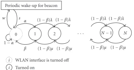
Actually, during the so-called idle-with-power-saving
1−α α
N−1 (1−β)λ (1−β)λ (1−β)λ (1−β)λ
β (1−β)μ (1−β)μ (1−β)μ (1−β)μ
Periodic wake-up for beacon
· · ·
0 1 2 N
i i
WLAN interface is turned off Turned on
w s
Figure 8: State transition diagram for WLAN interface and AP
buffer when PCP is not applied.
Letwandsdenote the wake-up rate during the idle state to receive a beacon signal from AP and the sleep rate during the idle state after receiving the beacon signals from the AP, respectively, both of which are fixed (seeFigure 8). Then, for theidle with power saving mode, the rate, at which WLAN interface is turned on, can be characterized as follows:
pw/oPCP same as the RNC buffer, the amount of packets dropped is also the same as the case of PCP withn=1.
Now, we can compute the average power consumed for a non-communication state during unit timet. Let Ci and
Cd be the power consumed for receiving beacon/data and
the baseline power consumption for the idle period, respec-tively. LetCiabe the power consumption due to the waking
up from the inactive state to receive the incoming data which is vertically handed offfrom the WWAN. For PCP, there is no baseline power consumption since the mobile node goes to inactive state when not transmitting data. Then, for this non-communication state, the average power-consumption during timetis
PWnc=
where in general,Cia is known to be greater thanCiso that
CiandCiaare set to 0.68 W and 1 W, respectively, whileCdis
assumed to have the value of 0.06 W. These values were taken from [19].
To obtain some simulation results (refer toSection 4) as well as numerical results, we have assumed that during the on period, the downlink transmission rate to the mobile node is 80 Kbps, which is an upper bound on the rate achievable by a 4-downlink slot GPRS mobile node that is capable of coding schemes up to CS-4, andtonis set to either 120 or 360 seconds. It is also assumed that the initialization time for the WLAN interface,ti, is one second and the buffer size,Lb, is
set to 20 KB.
For a typical WLAN interface with power saving mode, beacons are only sent at fixed intervals and a typical value
is in the order of 100 milliseconds (e.g., Lucent Orinoco 802.11b AP sends beacons at an interval of 102.4 millisec-onds). Thus, the beacon period,s−1, can be set to 100 mil-liseconds. We assume that the WLAN interface does not have to stay awake after the beacon reception. LetLBEACONbe the length of the beacon management frame assumed to be about fifty bytes long. Then, the processing time for beacon signal, 1/w, is expressed asLbeacon/B+ processing time at interface, whereBis the channel bit rate.
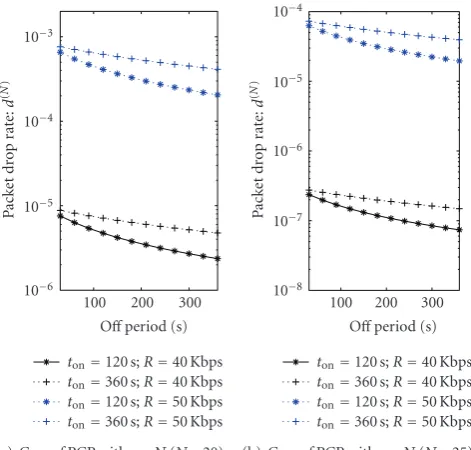
In Figures 9(a), 9(b), 9(c), and 9(d), the average power consumed by the WLAN interface for the non-communication state, PWnc, is plotted as a function of the offperiod ranging from 30 to 360 seconds forR = 40 and 50 Kbps, whereRdenotes the data rate to the BS durington with a packet size equal to 1000 bytes.
Comparing Figures 9(a) and 9(b) with Figures 9(c) and 9(d), the average power consumption for the non-communication state obtained with a typical WLAN sys-tem is higher than the proposed PCP syssys-tem, where the power consumption for PCP withn=Nis lower than PCP with n = 1 over all the ranges of off period considered forR = 40 Kbps and 50 Kbps. The performance improve-ment brought by PCP withn =Nover PCP withn =1 is around 16% and 46% greater whenR=40 Kbps than when
R=50 Kbps, forton=120 and 360 s, respectively. Thus un-der the same active period, the higher the data rate gets, the higher the power consumed for a non-communication state of PCP withn=Nbecomes because the data packets from the traffic with a higher data rate fill the buffer faster. From Figures9(a)and9(d), it is noted that in terms of power con-sumption, the above observed performance improvement is still valid, irrespective of the active period length (either 120 or 360 seconds). The graphs inFigure 9also indicate that as the offperiod increases, the power consumed by the PCP sys-tem decreases.
Figures10(a),10(b),10(c), and10(d)show the average number of packets in the RNC buffer during a vertical han-dover to WLAN. The numerical results inFigure 10are ob-tained from (7). We observe from Figures 10(a)and10(b) that as the offperiod increases, the average number of pack-ets in the buffer decreases. For a smaller offperiod, the dif-ference between the average number of packets in the buffer is also smaller for both cases ofton =120 and 360 seconds. The curves in Figures 10(c)and10(d)indicate that as the number of packets in the buffer increases, the power-on rate of WLAN interface increases as well. It is expected that the increasing number of packets in the buffer means that a pre-defined value of the thresholdnis reached faster with our PCP.
100 200 300 Figure9: Average power consumption for non-communication state versus varying offperiod.
30 100 200 300 360 Figure10: The average number of packets in the buffer at RNC for varying offperiod and power-on rate whenton=120 and 360 seconds.
100 200 300 Figure11: Packet-drop rate at the RNC buffer for varying off
pe-riod when thresholdn=N(i.e., the worst case of packet dropping
for PCP).
Figure 11(a), we know that the packet-drop rate of PCP with n = N decreases as the buffer size is increased (if the buffer size is larger than TCP window size, no packet
drop occurs). That means that setting the threshold n to
k < N makes the proposed PCP achieve lower packet-drop rate and higher power consumption than PCP withn=N. Thus the value of threshold, n(1 ≤ n ≤ N), will have an impact on the performance of both the power consump-tion for the non-communicaconsump-tion state and the packet-drop rate.
4. PERFORMANCE EVALUATION THROUGH SIMULATION
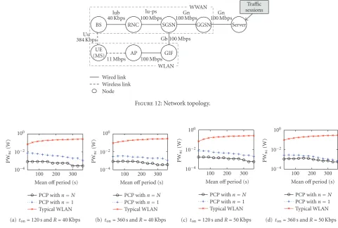
BS RNC SGSN GGSN
WWAN sessionsTraffic
Uu
11 Mbps 100 Mbps
Figure12: Network topology.
100 200 300 Figure13: Power consumption for non-communication state versus varying mean offperiod.
network (UTRAN) support modules [34] and the mobility package from [35].
Our simulation focuses on conversational and streaming classes inTable 2, and hence the downlink traffic source is simulated with the on-offmodel explained inSection 3. Not-ing that current multimedia applications use user decagram protocol (UDP) as the underlying transport protocol, UDP is used as the transport layer in our simulation.
The system and traffic source parameter values for the simulation model are the same as those used in Section 3. According to the traffic model inSection 3, the channel stays in each on and offstate according to an exponentially dis-tributed duration and the traffic arriving at the per-user buffer follows a Poisson process. The tests were carried out using the network topology shown inFigure 12 where the transmission rate of each wireless link is indicated. We set the data rate between the mobile node and the AP to 11 Mbps assuming an IEEE 802.11b WLAN. The data rate per con-nection between the RNC and the BS is set to 40 Kbps, sup-posing that the maximum transmission rate of the UMTS system is 384 Kbps, but the scheduler in the RNC provides 40 Kbps data rate for a connection. Our simulation results are obtained with a 95% confidence interval. The simulations can be extended to a system with more APs but we wanted to capture the key performance comparisons between our PCP and a typical WLAN system using a simple network with a
smaller capacity in order to keep the simulation time man-ageable.
In our simulation, we found that in the simulation tests, WLAN interface may not be turned on at the exact moment when the buffer at RNC reaches a thresholdn. This can be caused by the link delay and a time difference between the moment when the buffer at RNC reaches a thresholdn, and the moment when the paging signal to wake up the WLAN interface is sent to the mobile node. Discrete-event genera-tion characteristics of the NS2 simulator also have an impact on the time difference. Thus the values of the simulation sults do not exactly match with those of the numerical re-sults, whereas the power consumption behavior observed in the simulation results is aligned with the numerical results.
Figure 13plots the power consumed by the WLAN in-terface for a non-communication state versus the off pe-riod ranging from 30 to 360 seconds for different values of
Table3: Performance improvement (%) of PCP over POD in terms of power consumption.
R Performance improvement of PCP over POD
toff n=1 n=10 n=N(=20)
ton=12 s
40 Kbps
10 s 62.86% 91.20% 91.20%
20 s 39.76% 83.22% 83.22%
30 s 73.15% 79.97% 79.97%
50 Kbps
10 s 33.35% 58.69% 71.82%
20 s 10.36% 45.24% 68.00%
30 s 8.27% 42.11% 74.80%
ton=36 s
40 Kbps
10 s 41.77% 89.15% 89.15%
20 s 46.32% 87.87% 87.87%
30 s 33.03% 83.78% 83.78%
50 Kbps Figure14: Average packet-drop rate at the RNC buffer for varying
mean offperiod.
PCP withn=1 is 12% and 38% greater than when the data rate is 50 Kbps, forton =120 and 360 seconds, respectively. The same phenomenon is observed for a smaller active pe-riod,ton = 120 seconds (about the same, and 26% greater for 40 and 50 Kbps, resp.) compared with ton = 360 sec-onds. Hence it can be known from these results that PCP with n = N works better with regard to the power con-sumed for a non-communication state, compared to PCP withn=1 when the data rate is lower and/or the active pe-riod is smaller. However, considering that mobile users do not always download the traffic with a low data rate and/or small active period, it is desirable to make the threshold
n less than the maximum buffer size. This is clearly
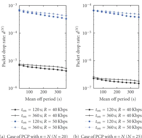
indi-cated from the packet-loss rate shown in Figure 14as well asFigure 9.
Figure 14shows the packet-drop rate during the vertical handover to WLAN for PCP withn=N. On the other hand, there was no packet dropping for PCP with n = 1. From Figure 14as well as Figure 11in the numerical results sec-tion, we observe that there is a tradeoffbetween the power consumption and the data loss in the proposed PCP system with a larger threshold,n. That is, the PCP system with larger thresholdnwill incur a lower power consumption at the cost of a greater data loss so that the thresholdnshould be set to a value smaller than the RNC buffer size (e.g., 1) if the network manager places more importance on the data-loss performance.
Figure 15plots the total power-on duration during the overall simulation time as a function of the off period in the simulation network. In Figure 15, PCP achieves a bet-ter performance than a typical WLAN in bet-terms of the total power-on duration. Accordingly, we know that the reduction of power consumption as seen inFigure 13results from the reduction of the total power-on duration because the mobile node is able to stay in a non-communication state without a periodic waking up under our PCP.
100 200 300 Figure15: Total power-on duration of WLAN interface for varying mean offperiod.
per-user buffer reaches the given threshold. This trend, with respect to the threshold, is the same for both on periods and both data rates.
From these results inTable 3, it can also be observed that though the absolute performance of PCP is better than that of POD as a whole, its margin of performance improvement is less forR = 50 Kbps than forR = 40 Kbps. We ascribe this observation to the fact that the occupancy of the buffer reachesnmore quickly for higher data rate. Thus for long-lived/real-time multimedia traffic, the threshold should be set lower than that for short/best-effort traffic.
5. CONCLUSION
In this paper, we propose a power-efficient communication protocol (PCP) for heterogeneous wireless networks, that utilizes the paging channel of cellular networks in order to turn offthe WLAN interface completely during the idle time. In other words, we aim to save the power consumption re-sulting from periodic wake-ups during the idle time. The de-tailed signaling for the PCP system is presented. Further, our proposed PCP is designed to avoid repetitive turn-on/-off ac-tions which consume a great amount of power by turning on the WLAN interface when the number of packets in the buffer at RNC reaches a certain thresholdn.
Performance results for the proposed PCP system are de-rived from an analytical model as well as simulations in terms of power consumption and data loss due to RNC buffer over-flow during a vertical handover to WLAN. The numerical and simulation results show that the power consumed in a non-communication state for our PCP system is lower than a typical WLAN system because for the idle time, the power consumption resulting from the periodic wake-up is elimi-nated, whereas the PCP system with a larger thresholdnwill incur a lower power consumption at a cost of greater data loss.
Finally, we expect to expand on this work in the future by developing a loose-coupling-architecture-based signaling system which will be able to wake up the WLAN interface, in the place of the WWAN paging and further investigate the impact of the developed signaling on the PCP system.
ACKNOWLEDGMENT
This work was supported by Grant no. R01-2006-000-10614-0 from the Basic Research Program of the Korean Science and Engineering Foundation.
REFERENCES
[1] IEEE Standard 802.21 Working Group, “Draft IEEE standard for local and metropolitan area networks: media independent handover services,” March 2006.
[2] J. McNair and F. Zhu, “Vertical handoffs in fourth-generation
multinetwork environments,”IEEE Wireless Communications,
vol. 11, no. 3, pp. 8–15, 2004.
[3] C. Guo, Z. Guo, Q. Zhang, and W. Zhu, “A seamless and proac-tive end-to-end mobility solution for roaming across
hetero-geneous wireless networks,”IEEE Journal on Selected Areas in
Communications, vol. 22, no. 5, pp. 834–848, 2004.
[4] R. Chakravorty, P. Vidales, K. Subramanian, I. Pratt, and J. Crowcroft, “Performance issues with vertical handovers— experiences from GPRS cellular and WLAN hot-spots
inte-gration,” inProceedings of the 2nd IEEE Annual Conference on
Pervasive Computing and Communications (PerCom ’04), pp. 155–164, Orlando, Fla, USA, March 2004.
[5] A. K. Salkintzis, C. Fors, and R. Pazhyannur, “WlAN-GPRS
integration for next-generation mobile data networks,”IEEE
Wireless Communications, vol. 9, no. 5, pp. 112–124, 2002.
[6] M. Ylianttila, J. M¨akel¨a, and K. Pahlavan, “Analysis of handoff
in a location-aware vertical multi-access network,”Computer
Networks, vol. 47, no. 2, pp. 185–201, 2005.
[7] S. K. Lee, S. H. Seo, and N. Golmie, “An efficient power-saving
mechanism for integration of WLAN and cellular networks,”
IEEE Communications Letters, vol. 9, no. 12, pp. 1052–1054, 2005.
[8] T. Rappaport, “Convergence of cellular and wireless LAN:
hotspot traffic statistics and user trends,” http://users.ece
.utexas.edu/∼wireless/Montage%20Meeting%20Minutes/ CTIATalk March04.pdf.
[9] G. Anastasi, M. Conti, and W. Lapenna, “A power-saving net-work architecture for accessing the internet from mobile
com-puters: design, implementation and measurements,”
Com-puter Journal, vol. 46, no. 1, pp. 3–15, 2003.
[11] V. K. Varma, S. Ramesh, K. D. Wong, M. Barton, G.
Hay-ward, and J. A. Friedhoffer, “Mobility management in
inte-grated UMTS/WLAN networks,” inProceedings of the IEEE
In-ternational Conference on Communications (ICC ’03), vol. 2, no. 1, pp. 1048–1053, Anchorage, Alaska, USA, May 2003. [12] 3GPP, “Architecture enhancements for non-3GPP accesses
(Release 8),” Technical Specification TS 23.402, v1.3.0, 3GPP, September 2007.
[13] 3GPP, “Feasibility study of mobility between 3GPP-WLAN interworking and 3GPP systems (Release 8),” Tech. Rep. TR 23.827, v0.4.0, 3GPP, September 2007.
[14] 3GPP, “General packet radio service(GPRS); service descrip-tion stage 2 (Release 7),” Technical Specificadescrip-tion TS 23.060 v7.4.0, 3GPP, March 2007.
[15] R. Chary, et al., “Power management technologies for WLAN enabled handheld devices,” Intel Developer Forum, 2003. [16] M. Nam, N. Choi, Y. Seok, and Y. Choi, “WISE:
energy-efficient interface selection on vertical handoffbetween 3G
networks and WLANs,” in Proceedings of the 15th IEEE
In-ternational Symposium on PIMRC ’04, vol. 1, pp. 692–698, Barcelona, Spain, September 2004.
[17] Option Wireless Technology, “Specifications of globetrotter,” http://www.option.be/products/2 1 1 specifications.shtml. [18] Atheros Communications, “Power consumption and energy
efficiency comparisons of WLAN products,” http://www
.atheros.com/pt/whitepapers/atheros power whitepaper.pdf, 2003.
[19] K. Mahmud, M. Inoue, H. Murakami, M. Hasegawa, and H. Morikawa, “Energy consumption measurement of wireless interfaces in multi-service user terminals for heterogeneous
wireless networks,”IEICE Transactions on Communications,
vol. E88-B, no. 3, pp. 1097–1109, 2005.
[20] 3GPP, “UTRAN overall description,” Technical Specification TS 25.401, v6.5, 3GPP, December 2004.
[21] 3GPP, “Radio link control (RLC) protocol specification,” Tech-nical Specification TS 25.322, v6.2, 3GPP, December 2004. [22] 3GPP, “Quality of service (QoS) concept and architecture
(Re-lease 7),” Technical Specification TS 23.107, v7.0.0, 3GPP, June 2007.
[23] M. C. Chan and R. Ramjee, “Improving TCP/IP performance
over third generation wireless networks,” inProceedings of the
23rd Annual Joint Conference of the IEEE Computer and Com-munications Societies (INFOCOM ’04), vol. 3, pp. 1893–1904, Hong Kong, March 2004.
[24] H. Wang, D. Prasad, O. Teyeb, and H. Schwefel, “Pefor-mance enhancements of UMTS networks using end-to-end
QoS provisioning,” in Proceedings of the 8th International
Symposium on Wireless Personal Multimedia Communications (WPMC ’05), Aalborg, Denmark, September 2005.
[25] P. T. Brady, “A model for generating on-offspeech patterns in
two-way conversation,”Bell System Technical Journal, vol. 48,
pp. 2445–2472, 1969.
[26] C.-N. Chuah and R. H. Katz, “Characterizing packet audio
streams from Internet multimedia applications,” in
Proceed-ings of the IEEE International Conference on Communications (ICC ’02), vol. 2, pp. 1199–1203, New York, NY, USA, April-May 2002.
[27] R. B. Ali, S. Pierre, and Y. Lemieux, “UMTS-to-IP QoS
map-ping for voice and video telephony services,”IEEE Network,
vol. 19, no. 2, pp. 26–32, 2005.
[28] M. Stemm and R. H. Katz, “Vertical handoffs in wireless
over-lay networks,”Mobile Networks and Applications, vol. 3, no. 4,
pp. 335–350, 1998.
[29] R. G. Mukhtar, S. V. Hanly, and L. H. Andrew, “Efficient
inter-net traffic delivery over wireless networks,”IEEE
Communica-tions Magazine, vol. 41, no. 12, pp. 46–53, 2003.
[30] A. Gurtov, “Efficient data transport in wireless overlay
net-works,” Academic dissertation, University of Helsinki, Fac-ulty of Science, Department of Computer Science and Inter-national Computer Science Institute, Helsinki, Finland, April 2004.
[31] V. D. Park and M. S. Corson, “User data models for
an IP-based cellular network,” http://www.ieee802.org/20/
Contribs/C802.20-03-13r1.pdf, 2003.
[32] E. Shih, P. Bahl, and M. J. Sinclair, “Wake on wireless: an event driven energy saving strategy for battery operated devices,” in
Proceedings of the Annual International Conference on Mobile Computing and Networking (MobiCom ’02), pp. 160–171, At-lanta, Ga, USA, September 2002.
[33] “UCB/LBNL/VINT Network Simulator ns-2,”http://www.isi
.edu/nsnam/ns/.
[34] “Enhanced UMTS radio access network extensions for ns-2
(EURANE),”http://www.ti-wmc.nl/eurane/.
[35] “NIST Seamless and Secure Mobility Project,” http://www