IJEDR1603004
International Journal of Engineering Development and Research (www.ijedr.org)19
An optimized PHASeR Routing protocol based upon
AACO
1Manpreet Kaur, 2Jyoti Saxsena
1Giani Zail Singh Campus College of Engineering, 2 Giani Zail Singh Campus College of Engineering
________________________________________________________________________________________________________
Abstract - This paper presents a optimized routing protocol named PHASeR(proactive highly ambulatory sensing routing) for mobile wireless sensor networks (MWSN). This protocol uses a simple hop count metric to enable the dynamic and robust routing of data towards sink. It is motivated by the application of radiation mapping. PHASeR maintains gradient metric in mobile network using a global TDMA MAC layer. It also uses the technique of blind forwarding to pass messages through the network in multipath manner. Fading problem occurs in PHASeR protocol due to long time transmission and due to any environmental change that affects the energy consumption of signal. AACO is the optimization technique used in this research paper to cop up with the signal fading in PHASeR.
Keywords - Mobile Wireless Sensor Networks, Routing Protocols, PHASeR , ACO, AACO
________________________________________________________________________________________________________
I. INTRODUCTION
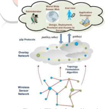
A wireless sensor network [1] is a network formed by large no. of sensor nodes where each node is equipped with sensor to detect physical phenomenon such as light, heat, pressure the acquired data is transmitted to the gateway, which can operate independently of the host system where the data is processed and analyzed. Sensor nodes monitor the collected data to transmit along to other sensor nodes by hopping. During this process of transmission the monitored data may be handled by multiple nodes to get to gateway nodes after multihop routing and finally reach the management nodes through the internet or satellite.
However in some situations the sensor nodes maybe required to be dynamic, creating mobile wireless sensor network (MWSN). MWSNs have no fixed topology which makes routing difficult due to frequent link breaks, but the main advantage is increased coverage area. Mobile nodes maybe required for moveable objects in smart environments, people who require constant health monitoring [2], research on wildlife [3] or surveillance performed by drones [4]. Protocols designed for these types of emerging applications require high packet delivery reliability and low overhead to decrease latency even in highly mobile environments. Routing in mobile wireless sensor networks differs from conventional routing in fixed networks in various ways. Many routing algorithms were developed for wireless networks in general. The next sections will include the routing protocols used in MWSN. Section 2 will outline the description of PHASeR protocol that how the protocol works and its drawbacks. Section 3 then presents the optimization technique used to overcome that drawback and describes the performance metrics. Section 5 includes the simulation results and discussion before the paper is concluded in section 6.
Figure 1: Wireless Sensor Network II. ROUTING PROTOCOLS IN WSN
IJEDR1603004
International Journal of Engineering Development and Research (www.ijedr.org)20
(LEACH) which is highly energy efficient and provides less latency and high throughput. The main drawback of LEACH is that it assumes all nodes to be homogeneous which is practically not usual as heterogeneity in energy is the most common case. Improved algorithm of LEACH is provided in Power-Efficient Gathering in Sensor Information Systems (PEGASIS). Unlike LEACH it avoids cluster formation and selection of one node is done to transmit data to sink rather than doing it by multiple nodes. So a chain is formed and only one node performs the task of transmission to the sink. PEGASIS uses a greedy approach and incase if there is any node failure then it bypass that node. So in each round node selection is done randomly thus reducing the per round energy consumption compared to LEACH [5]. With this improved protocol lifetime of the network is increased and clustering overhead is avoided. Similarly TEEN[6] is the another hierarchical protocol which is suitable for critical applications by adjusting the value of hard and soft threshold. Drawbacks of TEEN is removed in APTEEN[7].Another category of MWSN protocols is flat protocols which is further categorized as Reactive (on demand) protocol and the Proactive (table driven) protocols. Reactive protocol searches for the route in an on-demand manner and set the link in order to send out and accept the packet from a source node to destination node. Route discovery process is used in on demand routing by flooding the route request (RREQ) packets throughout the network [8]. Examples of reactive routing protocols are the dynamic source Routing (DSR), ad hoc on-demand distance vector routing (AODV). The proactive protocols are the protocols in which
each node in the network has routing table for the broadcast of the data packets and want to establish connection to other nodes in the network. These nodes keeps the record for all the destinations, number of hops required to arrive at each destination in the routing table. The routing entry is tagged with a sequence number which is created by the destination node
As such, the objective of Proactive Highly Ambulatory Sensor Routing (PHASeR) is to provide robust and timely data routing in the challenging mobile environment of radiation mapping. It is assumed that all of the nodes will be generating data periodically with fixed time intervals, which can be taken advantage of by letting each node periodically transmit in predefined slots. Given that there are a relatively small number of nodes, each one may be assigned a unique identification number, which will indicate the time slot in which the node should transmit.
III. PHASER
In PHASeR, each transmission is received by all of the transmitting nodes neighbors, this allows nodes to gather local topology information; namely the hop-counts of the nodes neighbors. Using this information a node will determine its own hop-count as one more than the lowest hop-count of its neighbors. So, if a node had three neighbors, with the hop-counts two, four and five, the node would set its own hop-count to three.[1] Since a deterministic global TDMA scheme is in use, a node will hear a single transmission from each of its neighbors in every cycle. This means that the node can update its hop-count every cycle, which will enable the gradient metric to be maintained across the whole network without flooding. This greatly reduces the protocols overhead and is one of its main advantages.[1] PHASeR uses the hop-count gradient to implement blind forwarding; so a transmission from a node is heard by all of its neighbors and it is the receiving nodes who independently decide whether they should forward any of the received data. In other words, when a node overhears a transmission it compares the hop-count of the transmitting nodes with its own. If the received hop-count is lower than its own, then the transmitting node is closer to the sink and the packet can be ignored. If the received hop-count is higher than its own, then the transmitting node is further from the sink, so the data is extracted from the packet and stored. If the received hop-count is equal to its own, then the transmitting node is the same distance from the sink, so the data is extracted from the packet, evaluated and either stored or dropped. [1]
The main drawback of PHASeR protocol is fading. Fading may either be due to multipath propagation, referred to as multipath induced fading, or due to shadowing from obstacles affecting the wave propagation, sometimes referred to as shadow fading. Fading can cause poor performance in a communication system because it can result in a loss of signal power without reducing the power of the noise. This signal loss can be over some or all of the signal bandwidth.[1]
IV. FADING
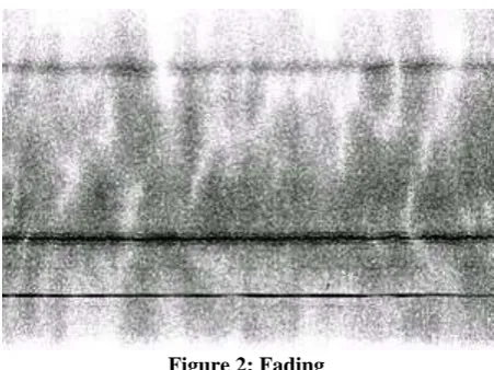
In wireless communications, fading is deviation of the attenuation affecting a signal over certain propagation media. The fading may vary with time, geographical position or radio frequency, and is often modeled as a random process. A fading channel is a communication channel that experiences fading. In wireless systems, fading may either be due to multipath propagation, referred to as multipath induced fading, or due to shadowing from obstacles affecting the wave propagation, sometimes referred to as shadow fading.
The terms slow and fast fading refer to the rate at which the magnitude and phase change imposed by the channel on the signal changes. The coherence time is a measure of the minimum time required for the magnitude change or phase change of the channel to become uncorrelated from its previous value.
Slow fading arises when the coherence time of the channel is large relative to the delay requirement of the application.[1] In this regime, the amplitude and phase change imposed by the channel can be considered roughly constant over the period of use. Slow fading can be caused by events such as shadowing, where a large obstruction such as a hill or large building obscures the main signal path between the transmitter and the receiver. The received power change caused by shadowing is often modeled using a log-normal distribution with a standard deviation according to the log-distance path loss model.
IJEDR1603004
International Journal of Engineering Development and Research (www.ijedr.org)21
Figure 2: FadingV. DEFINITION OF ENERGY EFFICIENCY
For a wireless networks, the devices operating on battery try to pursue the energy efficiency heuristically by reducing the energy they consumed, while maintaining acceptable performance of certain tasks. Using the power consumption is not only a single criterion for deciding energy efficiency. Actually, energy efficiency can be measured by the duration of the time over which the network can maintain a certain performance level, which is usually called as the network lifetime. Hence routing to maximize the lifetime of the network is different from minimum energy routing.
Minimum energy routes[1][6] sometimes attract more flows, and the nodes in these routes exhaust their energy very soon; hence the whole network cannot perform any task due to the failure on these nodes. In other words, the energy consumed is balanced consumed among nodes in the networks. Routing with maximum lifetime balances all the routes and nodes globally so that the network maintains certain performance level for a longer time. Hence, energy efficiency is not only measured by the power consumption but in more general it can be measured by the duration of time over which the network can maintain a certain performance level. There are lots of ways to categorize routing algorithms One is flooding and broadcast routing, which is often necessary during the operation of the wireless network, such as to discover node failure and broadcast some information. The second kind is multicast routing, which is very common in wireless networks, to communicate in a one-to-group fashion. The last is unicast, which is always in an end-to-end fashion and the most common kind of routing in networks. It goes without saying that node failure is very possible in the wireless network. Hence, saving energy when broadcasting in order to recover from the node failure or to re-routing around the failed nodes is essential. By the same token, multicast has the same challenge to achieve the energy efficiency [11][19]. For unicast, it is highly related to the node and link status, which require a wise way to do routing as well. Sometimes, shortest
path routing is possibly not the best choice from the energy efficiency point of view. Energy is a limiting factor in case of Ad-hoc networks[12]. Routing in ad-hoc networks has some unique characteristics. First-energy of nodes is crucial and depends upon battery which has limited power supply. Second-nodes can move in an uncontrolled manner so frequent route failures are possible. Third-wireless channels have lower and more variable bandwidth compare to wired network. Energy efficient routing protocols are the only solution to above situation. Most of the work of making protocols energy efficient has been done on “on demand routing protocols” because these protocols are more energy efficient rather than proactive protocols but still these have some drawbacks which have been discussed in the next section. Energy efficiency can also be achieved by sensible flooding at the route discovery process in reactive protocols. And energy efficiency can also be achieved by using efficient metric for route selection such as cost function, node energy, battery level etc. Here energy efficiency doesn’t mean only the less power consumption here energy efficiency means increasing the time duration in which any network maintains certain performance level.
VI. ANTCOLONYOPTIMIZATION (ACO) ANDADAPTIVEANTCOLONYOPTIMIZATION(AACO)
Ant colony optimization is a part of the larger field of swarm intelligence in which scientists study the behaviour patterns of bees, termites, ants and other social insects in order to simulate processes.
IJEDR1603004
International Journal of Engineering Development and Research (www.ijedr.org)22
However, the continued random selection of paths by individual ants helps the colony discover alternate routes and insures successful navigation around obstacles that interrupt a route. Trail selection by ants is a pseudo-random proportional process and is a key element of the simulation algorithm of ant colony optimization.Adaptive ACO: In this proposed method, Ant colony optimization algorithm with uniform mutation operator using self-adaptive approach is used. Here mutation operator is used for enhancing the algorithm escape from local optima. In this method, an additional operator, mutation operator, is used and the new mutation rate is generated by the self-adaptive approach using equation (1). Here ACO algorithm generates the current solution (w). By using mutation operator, random position is changed by new mutation rate in current solution(w). After changing random position, new solution (w’) is generated. Then the cost of this new solution (w’) is compared by the current solution (w), if the cost of new solution is less than ( or greater than) current solution, according to combinational problem, then new solution is replaced by current solution. This process is repeated until maximum iteration is not reached. The value of the current path and its reciprocal path is stored in table.
VII. PROBLEM FORMULATION
Existing technique presented an original routing protocol designed for MWSNs. It specifically targets the application of radiation mapping using UAVs. However, it should be noted that the protocol could be used in other similar scenarios and for different applications. PHASeR uses a novel, low overhead, method of maintaining a gradient metric, even in high speed scenarios, through the use of a global TDMA MAC layer. PHASeR is also particularly robust from its use of the blind forwarding technique, which allows data to simultaneously take multiple paths through the network. Extensive analysis and simulations, modelled on the radiation mapping application, have shown the protocol to be effective in a wide array of situations, over varying mobility, scalability and traffic levels. MACRO, AODV and OLSR results have also been given to illustrate the performance level of the routing protocols currently used in sensor network implementations.
Extensive analysis and simulations, modelled on the radiation mapping application, have shown the protocol to be effective in a wide array of situations, over varying mobility, scalability and traffic levels. MACRO, AODV and OLSR results have also been given to illustrate the performance level of the routing protocols currently used in sensor network implementations.
A fading channel is a communication channel that experiences fading. In wireless systems, fading may either be due to multipath propagation, referred to as multipath induced fading, or due to shadowing from obstacles affecting the wave propagation, sometimes referred to as shadow fading.
Fading can cause poor performance in a communication system because it can result in a loss of signal power without reducing the power of the noise. This signal loss can be over some or all of the signal bandwidth.
Fading can also be a problem as it changes over time: communication systems are often designed to adapt to such impairments, but the fading can change faster than the adaptations can be made. In such cases, the probability of experiencing a fade (and associated bit errors as the signal-to-noise ratio drops) on the channel becomes the limiting factor in the link's performance. The effects of fading can be combated by using diversity to transmit the signal over multiple channels that experience independent fading and coherently combining them at the receiver. The probability of experiencing a fade in this composite channel is then proportional to the probability that all the component channels simultaneously experience a fade, a much more unlikely event.
IJEDR1603004
International Journal of Engineering Development and Research (www.ijedr.org)23
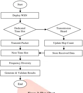
Figure 3: Flow ChartFigure 3 shows the flow chart for a single node’s operation at each timeslot. The node begins by determining if the current time slot is its own dedicated time slot, then it should compile a packet from the queued frames. Priority data is stored first and then any remaining room is filled with diversity data. The packet is then broadcast to any nodes within the transmission area.
IX. RESULTS AND DISCUSSION
In this research paper the effect on various QoS parameters such as Packet Delivery Ratio, Overheads, Average End-to-End Delay, Throughput, Average Energy Consumption have been seen by varying the no. of nodes i.e. 20,40,60.80 and 100 nodes at the constant speed of 100m/s.
Performance Metrics
1. Packet Delivery Ratio: The first metric is PDR, which is the number of packets successfully received Prx, per number of packets transmitted Ptx.
Given as PDR =Prx/Ptx
where Prx is packets received and Ptx is packets transmitted
As the TDMA MAC scheme is contention free there will be no loss from collisions. However, nodes being disconnected from the network and path breaks may cause packet losses.PDR ratio should be as high as so the network could give best results.
2. Average End-to-end Delay: The second metric is average end-to-end delay, it is the average between a packet being created and being delivered to the sink. The average delay in a TDMA multihop based protocol depends greatly on the order of the allocated time slots of the forwarding nodes. The best case scenario is that the forwarding nodes are in sequence.
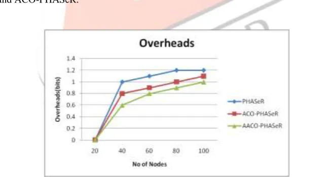
3. Overhead: Overhead is a major factor in designing routing protocols for mobile sensor networks since more no. of packets can cause congestion, which will limit the throughput of data. There are generally two types of overhead; packet overhead and control overhead. Packet overhead is the ratio of non-data bits to data bits in a data packet. Control overhead is the ratio of bits in control packets to bits in data packets. Control packets are often used to negotiate channel access, discover routes or share topology information.
4. Throughput: Throughput, is defined as the number of data bits successfully delivered to the sink, per second, over the entire simulation time.
5. Average Energy Consumption: Energy consumed in transmitting and receiving the message packets in a mobile wireless sensor network.
•Packet Delivery Ratio
Figure 4 shows the PDR in existing PHASeR, ACO and AACO. AACO-PHASeR shows the better results as compared to the ACO-PHASeR and PHASeR because if there is link breakage or there is a dead node in a network due to the more energy dissipation then we use the resiprocal path generated by AACO,as a result of which
Start
Deploy WSN
Dedicated Time Slot
Transmit Packet
Transmission Heard
Update Hop Count
Store Received Data Next Time Slot
Frequency Diversity
Generate & Validate Results
IJEDR1603004
International Journal of Engineering Development and Research (www.ijedr.org)24
Figure 4: Comparison of PDR in PHASeR, ACO-PHASeR, AACO-PHASeRlosses are reduced thus the packet drop is reduced as the result of which the packet delivery ratio is improved in AACO-PHASeR.
Average End-to-End Delay
Figure5. Comparison of Average End-to-end delay in PHASeR, ACO-PHASeR, AACO-PHASeR
Figure 5 shows the better results of average end- to-end delay in AACO-PHASeR. As the path is deviated load is less so the packets will reach to destination in time without any delay as the result of which end to end delay in the AACO-PHASeR is less as compare to PHASeR and ACO-PHASeR.
Overhead
Figure 6: Comparison of Overhead in PHASeR, ACO-PHASeR, AACO-PHASeR
Figure 6 shows low overhead result shown by AACO-PHASeR as compare to PHASeR. As the packet drop is reduced the packet delivery ratio is improved so all the packets are delivered in time so overhead is reduced in AACO-PHASeR.
IJEDR1603004
International Journal of Engineering Development and Research (www.ijedr.org)25
Figure 7 ThroughputFigure 7 shows that AACO-PHASeR shows better results as shown in graph. As the packets will take the reciprocal path more no. of packets will reach to the destination without any loss so as a result of which throughput of AACO-PHASeR is improved.
Average energy consumption
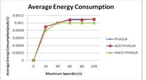
Figure 8. Average Energy Consumption in PHASeR, ACO-PHASeR, AACO-PHASeR
Figure 8 shows that there is less energy consumption in AACO-PHASeR than PHASeR. As the packet drop is less so the retransmission attempts for sending the message to receiver is decreased, so as the retransmission attempts is less so there is less energy dissipation due to which the average consumption of energy in optimized technique is less as compared to the existing protocol.
X. CONCLUSION
A wireless sensor network consists of three main components: nodes, gateways, and software. The spatially distributed measurement nodes interface with sensors to monitor assets or their environment. In the research proposal the optimized PHASeR protocol is implemented on the basis of AACO optimization scheme. AACO is used to provide a reciprocal path for every link in case of its failure. The proposed approach helps to reduce the load and drops in the network, so using the proposed methodology the QOS parameters are quite improved as shown in the result section.
XI. REFERENCES
[1]. T. Hayes, F.H. Ali, “Proactive Highly Ambulatory Sensor Routing (PHASeR) protocol for mobile wireless sensor networks”, Pervasive and Mobile Computing, Vol: 21, 2015, pp: 47-61
[2]. Satvir Singh, Meenaxi, “A Survey on Energy Efficient Routing in Wireless Sensor Networks”, International Journal of Advanced Research in Computer Science and Software Engineering, Volume 3, Issue 7, July 2013
[3]. K. Arun prabha, K. Hemapriya, “Energy Saving In Wireless Sensor Network Using Optimal Selective Forwarding Protocol”, International Journal of Advancements in Research & Technology, Volume 2, Issue1, January 2013
[4]. Neeraj Kumar, Manoj Kumar, and R. B. Patel, “A Secure and Energy Efficient Data Dissemination Protocol for Wireless Sensor Networks”, International Journal of Network Security, Volume 15, No.6, PP.490-500, November 2012
[5]. N. Akilandeswari, B. Santhi and B. Baranidharan, “A Survey on Energy Conservation Techniques in Wireless Sensor Networks”, ARPN Journal of Engineering and Applied Sciences, Volume 8, No. 4, April 2013
[6]. Eugene Shih, Seonghwan Cho, Nathan Ickes, Rex Min, Amit Sinha, Alice Wang, Anantha Chandrakasan, “Physical Layer Driven Protocol and Algorithm Design for energyefficient Wireless Sensor Networks” ,Department of Electrical Engineering and Computer Science, Massachusetts Institute of Technology, Cambridge, MA, USA
[7]. Shashidhar Rao Gandham, Milind Dawande, Ravi Prakash, S. Venkatesan, “Energy Efficient Schemes for Wireless Sensor Networks with Multiple Mobile Base Stations.”, Department of Computer Science, School of Management, University of Texas at Dallas ,Richardson
[8]. Mark Adam Perillo, “Role Assignment in Wireless Sensor Networks: Energy-Efficient Strategies and Algorithms” ,Department of Electrical and Computer Engineering , University of Rochester, New York,2007
IJEDR1603004
International Journal of Engineering Development and Research (www.ijedr.org)26
[10]. Wei Ye, John Heidemann, Deborah Estrin, “An Energy-Efficient MAC Protocol for Wireless Sensor Networks” [11]. Stefanos A. Nikolidakis, Dionisis Kandris, Dimitrios D. Vergados, Christos Douligeris, “Energy Efficient Routing inWireless Sensor Networks Through Balanced Clustering” , Department of Informatics, University of Piraeus, Greece [12]. Gyanendra Prasad Joshi, Seung Yeob Nam and Sung Won Kim, “Cognitive Radio Wireless Sensor Networks:
Applications, Challenges and Research Trends”, Department of Informatics, University of Piraeus, Greece,18 January 2013
[13]. Xun Li, Geoff V Merrett, Neil M White, “Energy-efficient Data Acquisition for Accurate Signal Estimation in Wireless Sensor Networks”, Journal on wireless Communications and Networking 2013
[14]. Karim Seada, Marco Zuniga, Ahmed Helmy, Bhaskar Krishnamachari, “Energy Efficient Forwarding Strategies for Geographic Routing in Lossy Wireless Sensor Networks” ,Department of Electrical Engineering, University of Southern California