Available Online atwww.ijcsmc.com
International Journal of Computer Science and Mobile Computing
A Monthly Journal of Computer Science and Information Technology
ISSN 2320–088X
IJCSMC, Vol. 4, Issue. 6, June 2015, pg.954 – 961
RESEARCH ARTICLE
A Hybrid Lossy Image Compression based on Wavelet
Transform, Polynomial Approximation Model, Bit
Plane Slicing and Absolute Moment Block Truncation
Dr. Ghadah Al-Khafaji
*, Dr. Salah Al-iesawi
&
Maha Abd Rajab
Dept. of Computer Science, Baghdad University, Dept. of Computer Science, Al-anbar University & Dept. of Computer Science Al-anbar University, Iraq
[email protected] salah_[email protected] [email protected]
Abstract
In this paper, a simple hybrid lossy image compression system is proposed, it is based on combining effective techniques, starts by wavelet transform that decompose the image signal followed by polynomial approximation model of linear based to compressed approximation image band. The error caused by applying polynonial approximation is coded using bit plane slice coding, on the other hand the absolute moment block truncation coding exploited to coded the detail sub bands. Then, the compressed information encoded using LZW, run length coding and Huffman coding techniques. The test results indicate that the proposed system can produce a balance between the compression performance and preserving the image quality.
1. Introduction
Image compression addresses the problem of reducing the amount of information required to represent a digital image [1-2]. Redundancy is a basic issue in digital image compression [3]. Image compression techniques are categorized into two main types depending on the redundancy removal way, namely Lossless and lossy [4]. Lossless image compression also called information preserving or error free techniques, as their name implicitly indicates, no loss of information, in which the data have been losslessly compressed, in other words, the original data can be reconstructed exactly from the compressed data based on the utilization of statistical redundancy alone (i.e. inter pixel redundancy and/or coding redundancy) with low compression rate, such as Huffman coding, Arithmetic coding, Run Length coding and Lempel-Ziv algorithm [5-8]. In lossy image compression that characterized by degrade image quality, in which the data have been lossly compressed, in other words, the original data can not be reconstructed exactly from the compressed data there is some degradation on image quality based on utilization of psycho-visual redundancy, either alone or combined with statistical redundancy with higher compression rate, such as Vector Quantization, Fractal, JPEG and Block Truncation coding [9-10]. Review on various lossless and lossy techniques can be found in [6-22].
coding, where many researchers have exploited to compress images, using a mathematical model that implicitly requires the form of the dependency (causal/ acausal), the order of the model (number of neighbours expolited) and the structure (1-D/2-D). Different modelling structures discussed in [7-18]. The predictive coding of polynomial based represents an alternative effective way to overcome traditional predictive coding restrictions mentioned above [19-11]. On the other hand, there is traditional simple fast techniques like bit-plane slicing image that sliced the image onto layers [20-21, 27] and block truncation coding (BTC) that ultized the first and second moments intelgently [13-15,19] with it is improved version that refereed as absolute moment block truncation coding(AMBTC) [16-17]. All the efficient standard techniques of hybrid base to increase the efficiency of performance, such as JPEG that exploited the discrete cosine transform (DCT) with predictive coding, review of hybrid techniques can be found in [24,25,26].
In this paper, a simple hybrid lossy techniques suggested for compressing gray images, based on utilizing the wavelet transform, polynomial representation of linear based along with the bit-plane slicing and AMBTC that exploted in an efficient way to improve the compression rate while preserving the image quality. The rest of the paper is organized as follows, section 2 contains comprehensive clarification of the proposed system; the result of the proposed system is given in section 3.
2. The Proposed System
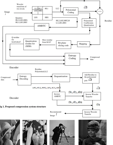
In order to implement the proposed hybrid lossy image compression system, following steps are applied and Figure (1) clearly illustrated the system:
Step1: Load the input uncompressed image I of size N×N.
Step 2: Apply two-layered wavelet transform of multiresolution based, by decomposing the image I into first layered wavelet of approximation (LL1) and detail sub bands (LH1,HL1,HH1), then subsequently the LL1 decomposed into approximation subband (LL2) and detail sub bands (LH2,HL2,HH2)
Step 3: Perform the polynomial prediction of linear based for the second approximation subband (LL2) using the steps below:
1- Partition the LL2 sub band into non-overlapped blocks of fixed size n×n, and performs the polynomial representation to the LL2 band blocks according to equations (1,2,3) [12]:
1
0 2 1
0
0 ( , ) (1)
1 n
j n
i
j i LL n
n
a
) 2 ( )
(
) ( ) , (
1
0 1
0
2 1
0 1
0 2
1
n
i n
j
c n
i n
j
c
x j
x j j i LL a
) 3 ( )
(
) ( ) , (
1
0 1
0
2 1
0 1
0 2
2
n
i n
j
c n
i n
j
c
y i
y i j i LL a
Where
LL
2(i,j)is the second approximation subband of the original image block of size (n×n) and) 4 ( 2
1
yc n
xc
2-Apply uniform scalar quantization to quantize the polynomial approximation coefficients, where each coefficient is quantized using different quantization step.
) 5 ( )
(
0 0
0 0
0
0
a a a a
a D Q SQ
SQ a round
Q
) 6 ( )
(
1 1 1 1
1
1
a a a a
a D Q SQ
SQ a round
Q
) 7 ( )
( 2 2 2
2 2
2
a a
a a
a D Q SQ
SQ a round
Where
0
a
Q ,
1
a
Q ,
2
a
Q are the polynomial quantized values
0 a SQ ,
1 a
SQ
2 a
SQ are the quantization steps of the polynomial coefficients. The quantization step values affected the image quality and the compression ratio, and
0
a
D
,
1
a
D ,Da2 are polynomial dequantized values.
3- Construct the predicted image value
I
~
using the dequantized polynomial coefficients for each encoded block representation:) 8 ( ) ( ) ( ~
2 1
0 a c a c
a D j x D i y
D
I
4- Find the residual or prediction error as difference between the original I and the predicted one
I
~
. )9 ( )
, ( ~ ) , ( )
,
(i j LL2 i j I i j
R
5- Mapping the residual image to positive values (i.e., all negative values are mapped to be odd while the positive values will be even) as in equation (10) to avoid coding complexity due to existence of positive and negative values.
) 10 ( 0
1 2
0 2
i i
i i
X if X
X if X
X
Where
X
iis thei
thelement residual value.6- Apply the bit plane slicing techniques of the resultant mapped residual image, the technique basically based on slice the image onto layers, range from layer0 corresponds to the Least Significant Layer (LSB) to layer7 corresponds to the
Most Significant Layer (MSB), only the high order layers from layer4 to layer7 are normally used, where the significant
details preserved.
7- Perform the scalar uniform quantizer to quantize the slice residual mapped image of high order layers, in other words the sliced residual image from layer4 to layer7 quantized with different quantization step as in equations (11,12,13,14).
)
11
(
)
(
4 4 44 4
4
Db
Qb
SQb
SQb
b
round
Qb
) 12 ( )
( 5 5 5
5 5
5 Db Qb SQb
SQb b round
Qb
)
13
(
)
(
6 6 66 6
6
Db
Qb
SQb
SQb
b
round
Qb
)
14
(
)
(
7 7 77 7
7
Db
Qb
SQb
SQb
b
round
Qb
8- Create the quantized residual mapped image
R
~
(
i
,
j
)
from the dequantized high layers above.Step 4: For the other detail sub-bands of the first and second layer (LH2,HL2,HH2,LH1,HL1andHH1) the absolute moment block truncation coding (AMBTC) exploited, the following steps are applied for each subband: 1- Partition the subband into non-overlapped blocks of fixed size m×m where m<=n (use 2×2 or 4×4).
2- Compute the mean of the partitioned block as equation (15).
) 15 ( ... ... ... ... ... 1
1
m
i i
x m x
Where
x
irepresent thei
th pixel value of the image block and m is the total number of pixels of block.3- Pixels in the image block are then divided into two ranges of values. The upper range is those gray levels which are greater than the block average gray level
(
x
)
and the remaining brought into the lower range. The mean of higherXHand the lower range XLare computed as equation (16 and 17).
)
16
...(
...
...
...
...
1
mx x
i H
i
x
K
x
) 17 ....( 1
m
x x
i L
i
x K block in pixel of number x
Where K is the number of pixels whose gray level is greater than
x
.Step 5: Use encoder to code the compress information that composed of binary image if detail subbands layers and the coefficients and quantized residual image, the encoder use LZW, Run Length Coding, which is passed through Huffman Coding.
Step 6: The decoder or reconstruction unit, starts by reconstruction the compressed values then applying the inverse process that reconstruct or rebuild the detail sub bands by replacing the 1 with XH and 0 with XLas equation(19)
) 19 .( ... ... ... 1
0
B X
B X
X
H L
Also the coefficients with the residual utilized to reconstruct the approximation subband of the second layer as equation(20)
)
20
....(
...
)...
,
(
~
)
,
(
~
)
,
(
ˆ
2
i
j
R
i
j
I
i
j
L
L
Lastly by applying the inverse wavelet transform to reconstruct the compressed imageIˆas equation(21).
)
21
...(
...
0
2
/
)
1
(
0
2
/
i i i
x
if
x
x
if
x
x
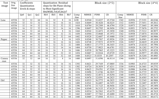
3. Experiments and Results
For testing the proposed system performance; four standard images are selected, the images of 256 gray levels(8 bits/pixel) of size 256×256( see Figure 2 for an overview). To evaluate the compression efficiency and image quality based on the compression ratio(CR), which is the ratio of the original image size to the compressed size, peak signal to noise ratio(PSNR) a large value implicitly means high image quality and close to the original image and vice versa with normalizes mean square error (NRMSE) where the range of the values between 0 and 1, if the value is close to zero refers to high image quality and vice versa as equations(22,23).
(ˆ( , ) ( , )
...(22)1
255 log
.
10 1
0 1
0
2 2
10
N
x N
y
y x I y x I N
N PSNR
) 23 ....( ... )
, (
)] , ( ) , ( ˆ [ )
ˆ , (
1
0 1
0
2 1
0
2 1
0
N
x N
y N
y N
x
y x I
y x I y x I I
I NRMSE
The result of the proposed system illustrates that the high compression rate is achieved because of utilization of effective multiresolution along with the efficient linear polynomial model of quantize three
coefficients(
a
0,
a
1,
a
2) and quantize the high order layer of residual image in which no need to extra information to be used. Implicitly meaning that the compression rate is directly affected by coefficients size compared to residual size, also the other detail subbands consumption of bytes compared to the linear polynomial part.Certainly, the quality of the compressed image is improves the number of quantization levels of both the approximation representation coefficients and for the high order layer of residual image increase. The higher the quality required the larger the number of quantization level that must be used.
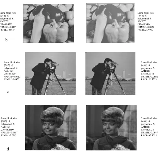
The result are shown in Table 1 lists the results for different values of the quantization step for the polynomial coefficients and for the high order layer of residual image, were selected to be between 16 to 64 levels for block size (2×2) and (4×4) to polynomial coefficients and absolute moment block truncation coding (AMBTC), also block size play an essential role in the process, the block size of (2×2) gives high image quality, while increase the block size to (4×4) the image quality become less( see Figure 3). Where compression ratio becomes higher and produce the trade-off between the quality desired and compression ratio. In other words , increase the block size gets bigger the higher compression ratio with higher error and vice versa. The quality of the compressed image is directly uninfluenced by using different quantization levels of the polynomial coefficients because of dominating the quantize high order layer of residual image, and also the other detail subbands are quantized based on two levels. Also the result demonstrates that the compression rates is directly affected by the size of polynomial approximation coefficients not the size of residual.
Image I
Polynomial Coding Wavelet
transform of
two levels LL2
Mapping
Residue
Bit plane slicing code Quantization
residue for (MSB)
Slice residue from b0-b7
Entropy Coding
Polynomial Coefficients Quantization n
AMBTC LL2 HL2 HL1 LH2 HH2
LH1 HH1
HL2,LH2,HH2,H
L1,LH1,HH1 Quantize
HL2,LH2,HH2, HL1,LH1,HH1
Compressed data Q residue
for b4,b5,b6,b7
Compressed data
Entropy Decoding
Dequantization Add Residue to the polynomial part
Inverse Wavelet Transfor
Inverse Wavelet Transfor Inverse
AMBTC
Reconstructed Image Residue,
Polynomial,LL2
Encoder
Decoder
Table (1) lists the results for different values of the quantization step for the polynomial
coefficients and for the high order layer of residual image, were selected to be between 16 to
64 level.
Block size {4*4} Block size {2*2}
Quantization Residual steps for Bit Plane slicing to Most Significant Bit(MSB), b4,b5,b6,b7 Coefficients
Quantization levels & steps
Orig. Size image Test image CR PSNR NRMSE Comp . Size CR PSNR NRMSE Comp . Size Rb7 Rb6 Rb5 Rb4 Qa2 Qa1 Qa0 8838.84 1935272 939754 2.81 8535988 .138119 939588 1438 24 8 .1 24 48 .1 .1 455.4 Lena 8731921 1935852 93975. 2..1 8439115 .93.419 939487 2818 24 24 24 24 .1 .1 .1 455.4 873.878 193.485 93979. 2.18 8438978 1731.87 939988 2829 .1 .1 .1 .1 .1 24 .1 455.4 8731951 1935494 939752 2..9 8437854 .931995 939479 2.74 24 24 .1 24 .1 .1 24 455.4 8837995 1935121 939754 2.89 853.859 .138891 939581 2888 24 8 24 24 48 .1 48 455.4 8838.84 1934898 9397.8 2.81 8532791 ..39888 939598 2859 .1 .1 .1 .1 48 48 48 455.4 8837894 1934757 9397.9 2..8 8538889 .134489 939518 2881 48 .1 24 48 .1 48 48 455.4 873.878 1438782 939881 2.18 85387.4 .939549 939589 2818 24 8 .1 24 48 .1 .1 455.4 Pepper 87381.8 14394.7 939719 2.14 8537597 1937191 939988 2814 24 24 24 24 .1 .1 .1 455.4 8739778 1534.29 939798 2.24 8435855 1932995 939825 2898 .1 .1 .1 .1 .1 24 .1 455.4 87359.8 1432181 939719 2.11 8434982 193791. 939959 2898 24 24 .1 24 .1 .1 24 455.4 87381.8 1435999 939882 2.14 853.11. .939845 9395.8 2884 24 8 24 24 48 .1 48 455.4 873.878 1437799 9398.1 2.18 8539917 .139248 939849 2858 .1 .1 .1 .1 48 48 48 455.4 8738785 1435188 939897 2.18 45.2597 31.0335 93951. 2888 48 .1 24 48 .1 48 48 455.4 8834875 1435827 939872 2.84 8438228 .234574 939879 2899 24 8 .1 24 48 .1 .1 455.4 Camera - man 87395.7 143891. 93979. 2..4 8939895 1739247 939412 2.71 24 24 24 24 .1 .1 .1 455.4 8731951 143.882 939724 2..9 8938122 183.8.7 939918 2.81 .1 .1 .1 .1 .1 24 .1 455.4 8837894 1438.44 939794 2..8 8935588 1734992 939415 2.98 24 24 .1 24 .1 .1 24 455.4 8835851 14359.5 939871 2.59 8431815 .234984 939874 2824 24 8 24 24 48 .1 48 455.4 8834291 14359.. 939871 2.88 8538178 .138891 939851 28.9 .1 .1 .1 .1 48 48 48 455.4 8839427 1438585 939798 2.88 8431815 .139.72 939894 2824 48 .1 24 48 .1 48 48 455.4 8837894 .135.85 939887 2..8 8431815 .435995 9395.. 2824 24 8 .1 24 48 .1 .1 455.4 Girl 8837995 .131899 939898 2.89 8435855 .438889 939582 2898 24 24 24 24 .1 .1 .1 455.4 873.878 .131429 939894 2.18 8437854 ..39215 939982 2.74 .1 .1 .1 .1 .1 24 .1 455.4 873.878 .1311.4 939889 2.18 8939217 .43.2.5 939587 2.78 24 24 .1 24 .1 .1 24 455.4 8839427 .135.51 939887 2.88 8534.97 .43554. 9395.8 28.4 24 8 24 24 48 .1 48 455.4 88389.8 .1355.5 939889 2.51 8538889 .93914. 939849 2881 .1 .1 .1 .1 48 48 48 455.4 8834291 .13...9 939847 2.88 8535222 .934788 939847 2889 48 .1 24 48 .1 48 48 455.4
Same block size {2×2} of polynomial & AMBTC CR=8532791 NRMSE=939598 PSNR=..39888
Fig 3. Compressed test images with different block size and different quality (a) Lena image,
(b)Pepper image,(c) Camera-man image and (d) Girl image respectively.
4.References
[1] G. Vijayvargiya, S. Silakari, and R. Pandey, “A Survey:Various Techniques of Image Compression”, (IJCSIS) International Journal of Computer Science and Information Security, Vol. 11, No. 10,October 2013.
[2] Y. S.AL–Mousawy, and S. S. Mahdi, “ImageCompression Using Wavelet Methods”, INCAS BULLETIN, ISSN: 2066 – 8201, Vol. 5, Issue: 1, pp. 13 – 18, 2013.
b
c
d
Same block size {2×2} of polynomial & AMBTC CR=8539917 NRMSE=939849 PSNR=.139248
Same block size {4×4} of polynomial & AMBTC CR=873.878 NRMSE=9398.1 PSNR=1437799
b
Same block size {2×2} of polynomial & AMBTC CR=8538178 NRMSE=939851 PSNR=.138891
Same block size {4×4} of polynomial & AMBTC CR=8834291 NRMSE=939871 PSNR=14359..
c
Same block size {2×2} of polynomial & AMBTC CR=8538889 NRMSE=939849 PSNR=.93914.
Same block size {4×4} of polynomial & AMBTC CR=88389.8 NRMSE=939889 PSNR=.1355.5
[4] S. K. Kapde, and S. V. Patil, “Image Compression Method”,International Journal of Engineering and Advanced Technology (IJEAT), ISSN: 2249 – 8958, Vol.2,Issue: 3, pp.426-429,February 2013.
[5] G. Al-Khafaji, “Image Compression Based on Quadtree and Polynomial” , International Journal of Computer Applications ., Vol. 76, No.3, pp. 31-37,August 2013.
[6] K.Sayood,“Introduction to Data Compression”, Third Edition,Elsevier Inc., San FranciscoUnited States of America, 2006.
[7] G. Al-Khafaji,and H. Al-Mahmood, “Lossless Compression of Medical Images using Multiresolution Polynomial Approximation Model”,International Journal of Computer Applications.,Vol. 76, No.3, pp. 38-42,August2013.
[8] Y. Q. Shi, and H. Sun, “Image and Video Compression for Multimedia Engineering : Fundamentals, Algorithms, and Standards”, Second Edition,CRC Press,Taylor & Francis Group, Broken Sound Parkway NW, 2008. [9] V.Dubey, N.K.Mittal, and S.G.kerhalkar, “A Review on Wavelet-Based Image Compression
Techniques”,International Journal of Scientific Engineering and Technology (IJSET),ISSN: 2277-158, Vol. 2, Issue:8, pp: 783-788, August2013.
[10] G. K. Al-Khafaji, “Intra and inter frame compression for video streaming”, Ph.D. Thesis, Dept. Computer Science.,University of Exeter,Exeter United Kingdom.,February 2012.
[11] P. Arockia, J. Rani and V. Sadasivam, “Codevector Modeling Using Local Polynomial Regression for Vector Quantization Based Image Compression”, ICTACT Journal on Image and Video Processing, Vol.1, Issue: 1, pp.37-42,August 2010.
[12] L. E.George, and B. A. Sultan, “Image Compression Based On Wavelet, Polynomial and Quadtree”,Journal of Applied Computer Science & Mathematics,Vol.11, No.5, pp.15-20,2011.
[13] H. Almara'beh, K. Barhoum, and M. Ahed, “Grayscale Image Compression Based on Min Max Block Truncating Coding”, International Journal of Computer Science Issues(IJCSI),ISSN: 1694-0814,Vol. 8, Issue: 6, No. 1, pp.109-112, November 2011.
[14] A. Kumar, and P. Singh, “Enhanced Block Truncation Coding for Gray ScaleImage”,Int. J. Comp. Tech. Appl.,ISSN:2229-6093, Vol. 2, Issue:3, pp.525-529,2011.
[15] D. Mohammed, and F. Abou-Chadi,“Image Compression Using Block Truncation Coding”,Journal of Selected Areas in Telecommunications (JSAT), pp.9-13,February2011.
[16] A. N. Mohammed-Ali, “Image Compression Using Maximum Minimum BTC (MMBTC)”,Journal of Basrah Researches ((Sciences)).,ISSN: 1817-2695,Vol. 35, No.3, pp.27-47,June2009.
[17] D. Santosh, U. Varma, K.Varma, M. Jami, and V. Dileep, “Absolute Moment Block Truncation Coding for Color Image Compression”,International Journal of Innovative Technology and Exploring Engineering (IJITEE),ISSN: 2278-3075, Vol.2, Issue:6, pp. 53-59, May 2013.
[18] G. Al-Khafaji,and L. E. George, “Fast Lossless Compression of Medical Images based on Polynomial”,International Journal of Computer Applications., Vol. 70, No.15, pp. 28-32,May2013.
[19] G. Al-Khafaji, “Hybrid Image Compression Based on Polynomial and Block Truncation Coding”, International Conference on Electrical, Communication, Computer, Power, and Control Engineering (ICECCPCE13), Mosul Iraq, Dec. 2013.
[20] S. Halder, D. Bhattacharjee, M. Nasipuri, and D. K. Basu, “A Low Space Bit-Plane Slicing Based Image Storage Method using Extended JPEG Format”, International Journal of Emerging Technology and Advanced Engineering, ISSN: 2250-2459, Vol. 2, Issue: 4, pp.694-699, April2012.
[21] M.M. Sathik, and N. S. Parveen,“Feature Extraction On Colored X-Ray Images By Bitplane Slicing Technique”,International Journal of Engineering Science and Technology, ISSN: 0975-5462, Vol.2, No.7, pp.2820-2824, 2010.
[22] Amruta, S.G. and Sanjay L.N. 2013. A Review on Lossy to Lossless Image Coding. International Journal of Computer Applications (IJCA), 67(17), 9-16.
[23] M. M. Chowdhury, and A. Khatun, “Image Compression Using Discrete Wavelet Transform”, International Journal of Computer Science Issues(IJCSI), ISSN: 1694-0814, Vol. 9, Issue:4, No. 1, pp. 327-330, July 2012. [24] Mukherjee, A., Sarkar, M. and Halder, A. 2012. Predictive Lossless Color Image Compression using Arithmetic Operation. International Journal of Computer Applications, 43(5), 43-46.
[25] S.B and T.S, “ Hybrid transformation technique for image compression”, Journal of Theoretical and Applied Information Technology, Vol. 41, No. 2, July 2012.
[26] M.Singh, and A.Goswami, “ Image compression technique using hybrid discrete cosine transform(DCT) and discrete wavelet transform(DWT) method ”, International Journal of Advanced Research in Computer Science and Software Engineering, Vol.2, Issue :10, pp. 217-223, October, 2012.