Lei Xie1, 2, *, Yong-Chang Jiao1, Biao Du2, Ze-Yu Meng2, and Yan Shi1
Abstract—A novel wide-flare-angle corrugated horn covering the full Ku/Ka satellite communication frequency bands is designed and optimized. In order to satisfy the rigorous bandwidth requirements, a spline-profiled smooth section and a corrugated section with ring-loaded slots are introduced into the wide-flare-angle horn design. Instead of the “trial-and-error” method, the Differential Evolution (DE) algorithm is employed to obtain the optimum dimensions of the proposed horn. A prototype of the optimized horn is constructed and measured. Both simulated and measured results show that the proposed horn has good radiation and impedance performance. The performance of the horn is also demonstrated as a feed in a typical dual-reflector antenna. Simulation results show that the overall antenna system meets the usual performance requirements.
1. INTRODUCTION
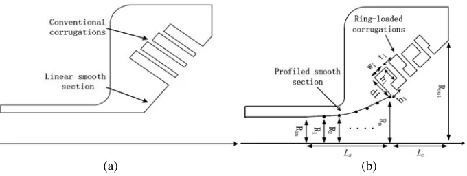
The wide-flare-angle corrugated horn originally proposed by Kay in 1966 [1] has found wide applications in reflector antenna systems. As shown in Figure 1(a), the horn structure proposed by Kay consists of a linear smooth section and a conventional corrugated section. Both experiment and simulation results show that such a feed can achieve satisfactory performance in a frequency range of 1.6 : 1. Some improved versions of the wide-flare-angle horn for dual-band or wide-band operations are also available in the literature, e.g., [2–6]. Among these designs, the ratio of the maximum to the minimum operation frequencies is no more than 1.9 : 1.
To meet the general specifications provided by a potential client, we investigate the possibility of designing a wide-flare-angle corrugated horn covering the full Ku/Ka satellite communication frequency bands [7, 8]:
• Ku receive frequency band: 10.70–12.75 GHz.
• Ku transmit frequency band: 13.75–14.50 GHz.
• Ka receive frequency band: 20.20–21.20 GHz (military); 19.20–20.20 GHz (commercial).
• Ka transmit frequency band: 30.00–31.00 GHz (military); 29.00–30.00 GHz (commercial).
Using the relative bandwidth concept, the full Ku/Ka bands represent a nearly 2.9 : 1 bandwidth ratio. It is a significant bandwidth for traditional corrugated horns hard to achieve. Most of the Ku/Ka-band feed horns presented in the literature have a coaxial configuration, and none of them can cover the full Ku/Ka bands [7, 8]. To satisfy the bandwidth requirements, some improvements are made on the conventional wide-flare-angle horn structure and the newly proposed horn structure is shown in Figure 1(b). This structure evolves from two horn design principles, i.e., adopting a spline profiled smooth section and a corrugated section with ring-loaded slots. The spline-profiled section provides a smooth transition from the circular waveguide to the corrugated section in a much wider bandwidth
Received 25 January 2016, Accepted 1 March 2016, Scheduled 8 March 2016
* Corresponding author: Lei Xie ([email protected]).
(a) (b)
Figure 1. Geometries of (a) the wide-flare-angle horn structure proposed by Kay and (b) the newly proposed horn structure.
than a linear smooth section. The corrugated section employs ring-loaded slots instead of conventional slots to obtain wider operation bandwidth. It is worth noting that although these two techniques have already been used in narrow-flare-angle horn designs their application in wide-flare-angle horn designs has rarely been investigated.
While the proposed horn structure is expected to have much better wideband performance, preliminary investigations show that it is not an easy task to obtain satisfactory performance by using the traditional “trial-and-error” method due to the complexity of the horn structure and the rigorous bandwidth requirements. Fortunately, with the advent of computer technology, accurate analysis methods and efficient optimization algorithms, it is now possible to design horns by an automatic optimization process [9–11].
This paper presents the design and optimization of a wide-flare-angle horn covering the full Ku/Ka bands by using the DE algorithm [12]. The optimized horn has satisfactory radiation and impedance performance over the operating bands, which validates the effectiveness of the design method and the superiority of the proposed horn structure. It should be mentioned that, to the best of our knowledge, the optimized horn is the first wide-flare-angle corrugated horn covering the full Ku/Ka satellite communication bands (representing a nearly 2.9 : 1 bandwidth ratio) reported in the literature and this is the first time the DE algorithm is applied to a corrugated horn optimization problem.
2. CORRUGATED HORN OPTIMIZATION
In performing the horn design, we proceed with the following targets in mind: 1) Ku/Ka-band frequency coverage;
2) The horn would be used as a feed for a ring-focus reflector antenna where the half-subtended angle from the focus to the edge of the sub-reflector is 37◦;
3) A Gaussian-like radiation pattern with the edge taper at 37◦ within the range of 9–16 dB.
In the optimization, the dimensions of the proposed horn are mathematically represented as the following vector
X = [Ls, Ri, tj, wj, bj, hj, dj], i= 1,2,3 and j= 1,2,3,4 (1)
g3(X) = max
1≤n≤Nf{ET(X, fn)} −ETmax≤0
g4(X) = ETmin− min
1≤n≤Nf{ET(X, fn)} ≤0. (2)
In Eq. (2), PE(X, fn, θ) and PH(X, fn, θ) are respectively the E- and H-plane patterns at the frequency pointfn. Nθis the number of angles sampled in the interval [0, θmax] within which we require a near circularly symmetric pattern. XP(X, fn), RL(X, fn) and ET(X, fn) are the maximum cross-polarization level, reflection coefficient and edge taper at the frequency pointfn, respectively. XPmax and RLmax are the allowed maximum cross-polarization level and reflection coefficient specified by the designer. ETmax and ETmin are the required maximum and minimum edge tapers over the operating bands.
To efficiently manage the constraints during the optimization, the constraint handling technique described in [14] is used. When two solutions Xi and Xj are compared, Xi is regarded as superior to Xj under the following conditions:
1) Xi is feasible andXj is infeasible.
2) BothXi andXj are feasible andXihas a smaller objective value (in a minimization problem) than Xj.
3) Both Xi and Xj are infeasible, but Xi has a smaller overall constraint violation V(Xi) computed by using
V (X) = m
i=1
wigi(X)
m
i=1
wi
(3)
wherewi= 1/Giis the weight parameter,Githe maximum violation of constraintgi(X) in the combined population, andmthe number of constraints. For the DE algorithm, the following parameters are used: scaling factor F = 0.5, crossover rate CR = 0.9, population size N P = 40, and the maximum number of generations is set to be 150. In the objective and constraint functionsXPmax,RLmax,ETmin,ETmax and θmax are set to be −25 dB, −25 dB, 9 dB, 17 dB and 37◦, respectively. The optimization process is executed automatically until the maximum generation is reached, and an optimum solution with satisfactory performance has been obtained. Each simulation run of CHAMP takes approximately 25 seconds on a dual core 2 GB RAM computer. The total execution time of the optimization process is about 41 hours. The optimized values of Ls, Lc, and Rout are 20.0 mm, 13.7 mm, and 27.0 mm, respectively.
3. SIMULATED AND MEASURED RESULTS
(a) (b)
Figure 2. A fabricated prototype of the optimized horn. (a) Top view. (b) Side View.
The simulated and measured VSWR results for the optimized horn are shown in Figure 4. In the operating bands, the simulated and measured VSWRs are lower than 1.13 and 1.16, respectively. The measured VSWR results are obtained by three independent measurements in the Ku band, the Ka receive band, and the Ka transmit band, respectively. Although there are some distortions between the simulated and measured VSWRs in the Ku band and the Ka receive band, they are within the reasonable range. Moreover, the measured VSWR results can fully meet our system requirements. Figure 5 shows the measured and simulated on-axis gains of the optimized horn. It can be seen that the measured gains of the horn agree well with the simulations and are within the range of 12.8 dBi to 15.5 dBi over the operating bands.
The simulated and measured maximum cross-polarization levels in the 45◦ plane versus frequency are plotted in Figure 6. The measured maximum cross-polarization levels are more than 30.1 dB and
(b)
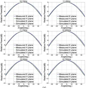
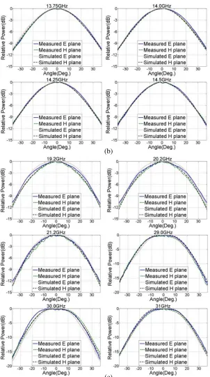
(c)
Figure 3. Simulated and measured radiation patterns of the optimized horn, (a) Ku receive band, (b) Ku transmit band, (c) Ka receive and transmit bands.
22.3 dB below the main beam level in the Ku and Ka band, respectively. In satellite communications, the frequency reuse using polarization diversity is mainly affected by the cross-polarization levels within the 1-dB beam width of the reflector antenna. As the 1-dB beam width of the reflector antenna is narrow, the relative higher off-axis cross-polarization levels of the horn will not affect the frequency reuse using polarization diversity.
Figure 4. Simulated and measured VSWRs of the optimized horn.
Figure 5. Simulated and measured on-axis gains of the optimized horn.
Figure 6. Simulated and measured maximum cross-polarization levels in the 45◦ plane.
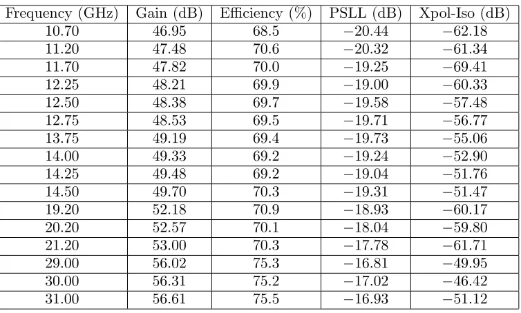
Table 1. Performance of the 2.4-m ring-focus dual-reflector antenna.
Frequency (GHz) Gain (dB) Efficiency (%) PSLL (dB) Xpol-Iso (dB)
10.70 46.95 68.5 −20.44 −62.18
11.20 47.48 70.6 −20.32 −61.34
11.70 47.82 70.0 −19.25 −69.41
12.25 48.21 69.9 −19.00 −60.33
12.50 48.38 69.7 −19.58 −57.48
12.75 48.53 69.5 −19.71 −56.77
13.75 49.19 69.4 −19.73 −55.06
14.00 49.33 69.2 −19.24 −52.90
14.25 49.48 69.2 −19.04 −51.76
14.50 49.70 70.3 −19.31 −51.47
19.20 52.18 70.9 −18.93 −60.17
20.20 52.57 70.1 −18.04 −59.80
21.20 53.00 70.3 −17.78 −61.71
29.00 56.02 75.3 −16.81 −49.95
30.00 56.31 75.2 −17.02 −46.42
31.00 56.61 75.5 −16.93 −51.12
antenna systems. The design results demonstrate the superiority of the proposed horn structure and the effectiveness of the DE-based design method. In addition, the simulated results indicate that the proposed wide-flare-angle horn structure is also prospective to continuously operate over a nearly 2.9 : 1 bandwidth, which is very attractive in radio astronomy and electronic warfare systems and will be investigated in our future work.
REFERENCES
1. Kay, A. F., “Wide-angle horn feed closely spaced to main reflector,” U.S. Patent 3 274 603, granted Sep. 20, 1966 (filed Apr. 3, 1963).
2. Thomas, B. M., K. J. Greene, and G. L. James, “A wide-band prime-focus horn for low-noise receiver applications,” IEEE Antennas Propag. Mag., Vol. 38, No. 11, 1898–1900, Nov. 1990. 3. Geen, D. and D. Smith, “Wide flare-angle horn antenna with means for radiating low levels of
cross polarisation in two widely separated frequency bands,” Antennas and Propagation Society International Symposium, 1996 AP-S Digest, Vol. 3, 2026–2029, 1996.
4. Granet, C., “Optimisation of a spline-profile corrugated horn for prime-focus operations,”Electron. Lett., Vol. 40, No. 9, 522–523, 2004.
5. Granet, C. and R. Gough, “Design of three prime-focus 12-mm-wavelength horns for the Parkes radio telescope,” Microw. Opt. Tech. Lett., Vol. 50, No. 10, 2537–2543, 2008.
6. Lehmensiek, R. and I. P. Theron, “L-band feed horn and orthogonal mode transducer for the KAT-7 radio telescope,” IEEE Trans. Antennas Propag., Vol. 59, No. 6, 1894–1901, Jun. 2011.
7. Granet, C., I. M. Davis, J. S. Kot, and G. Pope, “Theoretical design of a simultaneous Ku/Ka-band feed system,” Proceedings of the Fourth European Conference on Antennas and Propagation, 1–4, Barcelona, Spain, Apr. 2010.
8. Chang, Y.-C. and J. Hanlin, “Commercial Ka and Ku bands reflector antennas,” Antennas and Propagation Society International Symposium, 5175–5178, Honolulu, Jun. 2007.
9. Jamnejad, V. and A. Hoorfar, “Design of corrugated horn antennas by evolutionary optimization techniques,” IEEE Antennas and Wireless Propag. Lett., Vol. 3, 276–279, 2004.
10. Lucci, L., R. Nesti, G. Pelosi, and S. Selleri, “Phase center optimization in profiled corrugated circular horns with parallel genetic algorithms,” Progress In Electromagnetics Research, Vol. 46, 127–142, 2004.
11. Agastra, E., G. Bellaveglia, L. Lucci, R. Nesti, G. Pelosi, G. Ruggerini, and S. Selleri, “Genetic algorithm optimization of high-efficiency wide-band multimodal square horns for discrete lens,”
Progress In Electromagnetics Research, Vol. 83, 335–352, 2008.
12. Storn, R. and K. Price, “Differential evolution: A simple and efficient heuristic for global optimization over continuous spaces,”J. Global Optim., Vol. 11, 341–359, 1997.
13. TICRA, CHAMP, Version 2.1, Denmark. [Online]. Available: http://www.ticra.com.
14. Deb, K., “An efficient constraint handling method for genetic algorithms,” Comp. Methods Appl. Mech. Eng., Vol. 186, No. 2–4, 311–338, Jun. 2000.
![Improvement of Power System Performance Using Fuzzy Logic Based Interline Power Flow Controller [IPFC]](data:image/gif;base64,R0lGODlhAQABAIAAAP///wAAACH5BAEAAAAALAAAAAABAAEAAAICRAEAOw==)