Single-Feed Single-Patch Triple-Band Single-Beam/Dual-Beam
U-Slotted Patch Antenna
Huaxiao Lu*, Yuan’an Liu, Fang Liu, and Weimin Wang
Abstract—A novel single probe-fed, single-layer, and single-patch triple-band microstrip antenna is presented. By incorporating two identical U-slots in the patch whose length isλd instead of 1/2λd in a conventional patch, three operating bands are achieved. Dual-beam radiation pattern is obtained at the upper band, and a single broadside beam radiation pattern is obtained at each of the lower and middle bands. The antenna’s structure is simple. Only by using a single probe-fed point, the impedance matches well at all the three resonant frequencies. The measured and simulated results are in good agreement. The measured lower, middle, and upper bands are centered at 2.442 GHz, 3.505 GHz, and 5.787 GHz, respectively. The measured gains are 6.2 dBi at 2.442 GHz and 5.5 dBi at 3.505 GHz, respectively. At 5.787 GHz, the measured gains for the dual radiation beams are 8.4 dBi directed at 26◦ and 8.2 dBi directed at −38◦, respectively. The proposed antenna can be a candidate for WLAN 2.4 GHz, WLAN 5.8 GHz, and 3.5 GHz of 5G (the fifth-generation mobile communication) operation.
1. INTRODUCTION
The rapid development of modern wireless communication requires multiband antennas. There have been many techniques to design dual-band or triple-band antennas in the published literature. However, for triple-band antennas, most of them are monopole antennas [1–3] or dipole antennas [4, 5]. These antennas generally have wideband characteristics, but their radiation beams are omnidirectional or bidirectional. This reduces the antenna directivity and gain [6], and their back radiations bring interference to circuits which are assembled below the ground plane [7]. Microstrip antenna is a popular candidate in modern wireless communication because it has the advantages of low cost, low profile, lightweight, compactness, and easy integration with other circuits. There are many reports on microstrip antennas with dual-band [8–11] in published literature, and these dual-band antennas are either single layer [8–10] or stacked structure [11]. However, there are not many reports on microstrip antennas with triple-band [12–14] in published literatures. In [12], two pairs of different arc slots and eight stubs are cut in a rectangular patch to realize triple-band characteristic. In [13], a rectangular patch loaded with two different slots and a ground plane loaded with two identical L-shaped slots, two identical asymmetrical U-slots, and two identical rectangular ring-slots are used to realize the triple-band characteristic. Meanwhile, the antenna is fed by a microstrip line. In [14], two different stub-loaded concentric annular-rings and an inside small circular patch are used to realize the triple-band characteristic, and a cross-slot embedded in the ground plane is used to reduce the antenna size, but this cross-slot increases the back radiation. These triple-band antennas maintain the advantage of single layer, but their radiating elements are relatively complicated. Meanwhile, the gains of these antennas are not high enough. For instance, the gains for the triple-band antenna in [12] at the three resonant frequencies are 3.1 dBi, 4.4 dBi, and 2 dBi, respectively. The gains for the triple-band antenna
Received 1 September 2018, Accepted 23 October 2018, Scheduled 13 December 2018 * Corresponding author: Huaxiao Lu ([email protected]).
in [13] are 0.32 dBi, 1.2 dBi, and 1.5 dBi, respectively, and that for the triple-band antenna in [14] are 0.5 dBi, −0.5 dBi, and 2.1 dBi, respectively. Compared to aperture coupled feed or stacked structures which need relatively complex feeds or more than one layer or more than one patch, single feed single layer single patch antennas have attracted much attention due to the simple structure.
Dual/multi-beam antennas are antennas which have more than one directional beam from a single aperture, and they have the ability of covering multiple areas, which is useful for wireless communication or radar systems because the number of the required antennas is reduced, and the link quality is improved [15]. A wideband E-shaped patch antenna with dual-beam across the operating bandwidth is reported in [16]. A wideband dual-beam patch antenna with a cross-shaped probe is reported in [17]. To the best of the authors’ knowledge, in the published literature for realizing triple-band antennas, there is no published report on at least one band operating with dual radiation beams.
In this work, a triple-band microstrip antenna with two U-slots is presented and investigated. The antenna has only one feed, only one layer, and only one rectangular patch with two identical U-slots. The proposed antenna exhibits a single beam at the lower and middle bands, respectively, and exhibits a dual-beam at the upper band. The proposed antenna has the following advantages: (1) Its structure is simple, simpler than many other antennas designed for realizing triple-band characteristic. (2) One of the three bands, that is the upper band, is operating with dual-beam. (3) The feed is simple, and only by a single probe feed point, the proposed antenna matches well at all the three resonant frequencies. The current distributions on the surface of the U-slots loaded patch are presented to analyze the proposed antenna. Parametric studies on several parameters are presented. Furthermore, the parametric study on the arm length of the U-slots is carried out to demonstrate that the three resonant frequencies can be adjusted by tuning the arm length, which is more convenient than that reported in [18], where the two resonant frequencies can be adjusted through the shorting walls. The proposed antenna can switch from a triple-band one to a dual-band one by tuning the arm length of the U-slots as well. The measured and simulated results are in good agreement, and satisfactorily low cross-polarization levels are achieved due to the symmetric structure. The radiating element volume of the proposed antenna is 0.37λg ×0.16λg ×0.02λg (λg is the wavelength in the substrate at the lower resonant frequency), which is much smaller than that in [9, 10, 12]; meanwhile, the antenna’s gain is high enough. The design guidelines in this work provide guidance for the antenna’s design in theory, which is useful to reduce the cost time for design optimization.
2. ANTENNA CONFIGURATION AND DESIGN
2.1. Antenna Geometry
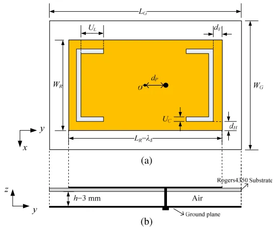
The configuration of the proposed antenna is shown in Fig. 1. The rectangular patch’s length LR is λd instead of λd/2 in a conventional microstrip antenna (λd is the wavelength in the substrate). For the sake of easy fabrication with printing technology, this rectangular patch is printed over a Rogers 4350 dielectric substrate with thin thickness of 0.762 mm, relative permittivity of 3.48, and loss tangent tanσ = 0.004. Two identical U-slots were symmetrically cut close to both the radiating edges and the nonradiating edges of the rectangular patch, respectively. Air, with thickness h = 3 mm and relative permittivityεr= 1, is used as the substrate. The patch is supported on the ground plane by plastic bolts. The dimension of the ground plane isLG×WG= 68 mm×43 mm. The overall antenna is geometrically symmetric along either the x-axis or the y-axis, which can maintain a low cross-polarization. An SMA connecter is used to feed the antenna, and the diameter of the coaxial probe is 1.3 mm. The final dimensions of the proposed antenna are given in Table 1.
Table 1. The dimensions of the proposed antenna.
Parameters LR WR dV dH UC UL dP
(b) (a)
Figure 1. The configuration of the proposed antenna: (a) top view; (b) side view.
(b)
(a) (c)
Figure 2. The simulated current distributions at: (a) fL (2.444 GHz); (b) fM (3.509 GHz); (c) fU (5.823 GHz).
2.2. Antenna Analysis and Design Guidance
respectively, and dual beams across the upper band. The design guidance for the proposed antenna is as follows.
First Step: The design of the proposed antenna begins with the design of a conventional microstrip
antenna operating at the upper band, and the initial dimensions of this conventional microstrip antenna can be calculated by formulas (1)–(5) given in [21].
WR = c0 2fr
2 εr+ 1
(1)
εeff = εr + 1
2 +
εr−1 2
1 +12h WR
−1 2
(2)
LR = c0 2fr√εeff −
2ΔLR (3)
ΔLR = 0.412h
(εeff + 0.3)·(WR/h+ 0.264) (εeff −0.258)·(WR/h+ 0.8)
(4)
LG = LR+ 6h, WG=WR+ 6h (5)
Considering that the upper band was conceived to operate in the range of 5 to 6 GHz, 5.5 GHz was selected as the initial value of fr. Meanwhile, the thickness of the used air substrate h = 3 mm and its relative permittivityεr= 1 should be taken into consideration. Thereafter, the electromagnetic software HFSS was used to fine-tune the initial dimensions of this conventional microstrip antenna with the objective that its impedance matches well at 5.5 GHz.
Second Step: Extend the patch length to two times of that in the fine-tuned conventional microstrip
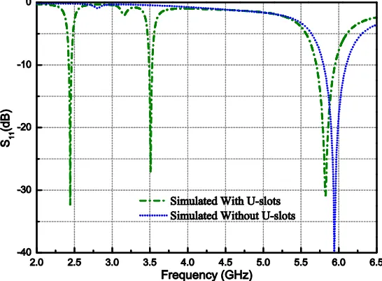
antenna in the first step, and the patch width in the first step is kept unchanged. Thus a rectangular patch with its lengthLR ofλdis obtained, and its simulated reflection coefficient is shown in Fig. 3. A patch antenna with its length of λd can have a dual-beam radiation pattern [20]. Thus, a rectangular patch antenna operating with a dual-beam radiation pattern is achieved in this step.
Figure 3. Simulated reflection coefficients of the proposed antenna without/with the U-slots.
Third Step: Two identical U-slots, which are used to create the lower and middle bands, were cut
symmetrically on the surface of the rectangular patch with its lengthLRofλd. For simplicity, the width UC of the U-slot is fixed at 1 mm in the design process.
Fourth Step: By following the above three steps, the initial dimensions of the proposed antenna
of the parameters including the feed position. The objective in this optimization was to ensure the impedance match well at the three resonant frequencies fL, fM, and fU, and the simulated reflection coefficient of the proposed antenna with the U-slots is shown in Fig. 3.
From the above-mentioned design guidance, the proposed antenna’s patch size (defined by both the patch length LR and width WR) is determined by the upper resonant frequency and not by the lower resonant frequency as most other multi-band antennas do. Specifically speaking, for the proposed antenna, the patch size was firstly achieved by the upper resonant frequency, that is to say, the patch length LR is calculated by formula (3) at the upper resonant frequency and is λd instead of λd/2. The patch width WR is calculated by formula (1) at the upper resonant frequency. Then create lower operating bands by cutting slots in the patch of the proposed antenna without increasing the antenna’s overall area. For most other multi-band antennas, such as antennas in [8–10, 12–14], where their patch sizes were firstly achieved by the lower resonant frequency, create higher operating bands by cutting slots in the patch.
2.3. Parametric Study
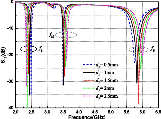
Figure 4 shows the simulated reflection coefficients (S11) for the proposed antenna with the variation of dV. Observe that with the increase ofdV, the lower resonant frequency fL of the lower band shifts moderately to lower frequency; the middle resonant frequencyfM of the middle band shifts moderately to higher frequency; and the upper resonant frequencyfU of the upper band shifts moderately to higher frequency.
Figure 4. The simulated reflection coefficients (S11) with the variation of dV.
Figure 5 shows the simulated reflection coefficients for the proposed antenna with the variation of dH. Observe that with the increase ofdH, the lower resonant frequencyfL shifts moderately to higher frequency; the middle resonant frequency fM shifts considerably to higher frequency; and the upper resonant frequencyfU is almost kept unchanged.
Figure 5. The simulated reflection coefficients (S11) with the variation of dH.
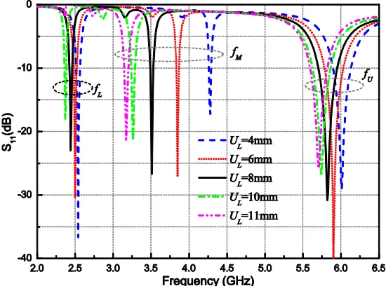
Figure 6. The simulated reflection coefficients (S11) with the variation of UL.
frequency decrease offM is faster than that offLandfU. WhenULis greater than 10 mm, the proposed antenna exhibits a dual-band characteristic. In this case, the two operating frequencies arefM andfU. From the above-mentioned analysis, the three resonant frequencies can be adjusted by the tuning ofUL, which is more convenient than that reported in [18], where the two resonant frequencies can be adjusted through the shorting walls connected between the square ring patch and the ground plane. Indeed, also by tuning UL, the proposed antenna can switch from a triple-band one to a dual-band one.
3. RESULTS AND DISCUSSIONS
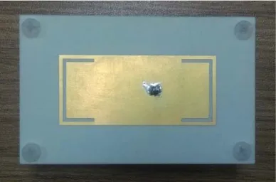
Figure 7. Photograph of the proposed antenna.
Figure 8. The measured and simulated reflection coefficients (S11) of the proposed antenna.
they are in good agreement. The measured impedance bandwidths with S11≤ −10 dB of the lower, middle, and upper operating bands are 1.39% (34 MHz) from 2.424 to 2.458 GHz, 1.71% (60 MHz) from 3.479 to 3.539 GHz, and 3.28% (190 MHz) from 5.692 to 5.882 GHz, respectively. Those simulated ones are 1.47% (36 MHz) from 2.426 to 2.462 GHz, 1.14% (40 MHz) from 3.489 to 3.529 GHz, and 4.24% (247 MHz) from 5.702 to 5.949 GHz), respectively. The measured three resonant frequencies are 2.442 GHz, 3.505 GHz, and 5.787 GHz, respectively, and those simulated ones are 2.444 GHz, 3.509 GHz, and 5.823 GHz, respectively. The three operating bands and resonant frequencies are frequently used in WLAN 2.4 GHz, 3.5 GHz of 5G (the fifth-generation mobile communication) operation, and WLAN 5.8 GHz [22]. The measured frequency ratios are: fU/fL= 2.37 andfM/fL= 1.44. Both the measured and simulated reflection coefficient S11results demonstrate that the proposed antenna has a promising aspect that its impedance matches well at the three resonant frequencies with only one single feed point. The discrepancy between the measured and simulated reflection coefficients S11 is due to the fabrication tolerance and assemble errors. The bandwidths of the three operating bands can be further expanded by increasing the thickness of the air substrate and accompanied with aperture coupled feed or a cross-shaped probe feed; however, this introduces a complicated antenna structure.
(b) (a)
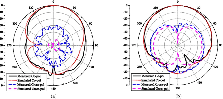
Figure 9. Measured and simulated normalized radiation patterns of the proposed triple-band antenna at 2.442 GHz: (a) yz plane; (b)xz plane.
(b) (a)
Figure 10. Measured and simulated normalized radiation patterns of the proposed triple-band antenna at 3.505 GHz: (a) yz plane; (b)xz plane.
(b) (a)
(d) (c)
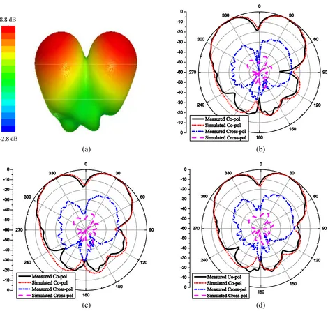
Figure 11. Measured and simulated normalized radiation patterns of the proposed triple-band antenna: (a) Simulated three-dimensional radiation pattern at 5.787 GHz; (b) 5.737 GHz (yz-plane); (c) 5.787 GHz (yz-plane); (d) 5.837 GHz (yz-plane).
From Fig. 9 and Fig. 10, observe that stable unidirectional single beam radiation pattern is achieved at the lower and middle bands, respectively. The measured and simulated gains in the broadside direction at 2.442 GHz are 6.2 dBi and 5.8 dBi, respectively, and those at 3.505 GHz are 5.5 dBi and 7.1 dBi, respectively. From Figs. 11(a)–(d), observe that dual-beam radiation pattern is achieved at the upper band, and the measured and simulated gains in the frequencies of the upper band are tabulated in Table 2. At 5.787 GHz, the measured gains of the left and right beams in the yz-plane are 8.2 dBi directed at−38◦ and 8.4 dBi directed at 26◦, respectively. Both the squints of the two beams are within 2◦ across the antenna operating band; meanwhile, the maximum difference between the maxima of the two beams is 0.3 dBi across the antenna operating band. The maximum difference between the beams’ maxima is a crucial criterion to evaluate the performance of a multi-beam antenna.
Table 2. The measured and simulated directions and gains for the left and right beams of the proposed antenna in theyz-plane at 5.737 GHz, 5.787 GHz, and 5.837 GHz.
Frequency (GHz)
Left Beam Right Beam Direction (θ◦m) Gain (dBi) Direction (θ◦m) Gain (dBi)
S M S M S M S M 5.737 −32 −40 8.9 8.1 29 26 8.8 8.5 5.787 −31 −38 8.8 8.2 29 26 8.8 8.4 5.837 −31 −38 8.7 7.9 28 26 8.6 8.4
Simulated,S; measured,M.
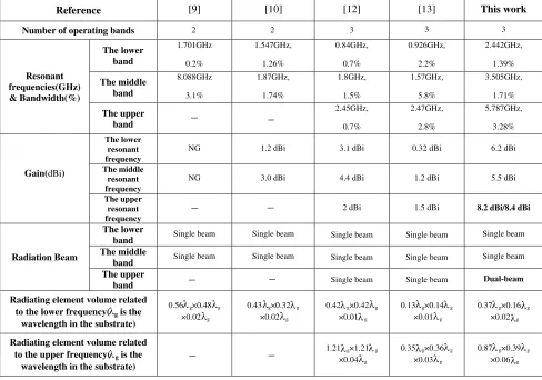
Table 3. Comparison with previous works.
Reference [9] [10] [12] [13] This work
Number of operating bands 3 3
Resonant frequencies(GHz) & Bandwidth(%) The lower band 1.701GHz 0.2% 1.547GHz, 1.26% 0.84GHz, 0.7% 0.926GHz, 2.2% 2.442GHz, 1.39% The middle band 8.088GHz 3.1% 1.87GHz, 1.74% 1.8GHz, 1.5% 1.57GHz, 5.8% 3.505GHz, 1.71% The upper
band −
2.45GHz, 0.7% 2.47GHz, 2.8% 5.787GHz, 3.28%
Gain(dBi)
The lower resonant frequency
NG 1.2 dBi 3.1 dBi 0.32 dBi 6.2 dBi
The middle resonant frequency
NG 3.0 dBi 4.4 dBi 1.2 dBi 5.5 dBi
The upper resonant frequency
2 dBi 1.5 dBi 8.2 dBi/8.4 dBi
Radiation Beam
The lower
band Single beam Single beam Single beam Single beam Single beam The middle
band Single beam Single beam Single beam Single beam Single beam The upper
band Single beam Single beam Dual-beam Radiating element volume related
to the lower frequency( g is the
wavelength in the substrate)
0.56 g×0.48 g
×0.02 g
0.43 g×0.32 g
×0.02 g
0.42 g×0.42 g
×0.01 g
0.13 g×0.14 g
×0.01 g
0.37 g×0.16 g
×0.02 g Radiating element volume related
to the upper frequency( g is the
wavelength in the substrate)
1.21 g×1.21 g
×0.04 g
0.35 g×0.36 g
×0.03λg
0.87 g×0.39 g
×0.06λg
λ λ λ λ λ λ λ λ λ λ λ λ λ λ λλ λ λ λ λ λ λ λ λ
2 2 3
−
− −
− −
− −
4. CONCLUSION
ACKNOWLEDGMENT
This work was supported by the National Natural Science Foundation of China under Grant 61701041 and Grant 61401042, and by Beijing Key Laboratory of Work Safety Intelligent Monitoring (Beijing University of Posts and Telecommunications).
REFERENCES
1. Wen, R., “Compact planar triple-band monopole antennas based on a single-loop resonator,”
Electronics Letters, Vol. 49, 916–918, 2013.
2. Kang, L., H. Wang, X. H. Wang, and X. Shi, “Compact ACS-fed monopole antenna with rectangular SRRS for tri-band operation,”Electronics Letters, Vol. 50, 1112–1114, 2014.
3. Chouti, L., I. Messaoudene, T. A. Denidni, and A. Benghalia, “Triple-band CPW-fed monopole antenna for WLAN/WiMAX applications,”Progress In Electromagnetics Research Letters, Vol. 69, 1–7, 2017.
4. Chen, S. W., D. Y. Wang, and W. H. Tu, “Dual-band/tri-band/broadband CPW-fed stepped-impedance slot dipole antennas,”IEEE Transactions on Antennas and Propagation, Vol. 62, 485– 490, 2014.
5. Dang, L., Z. Y. Lei, Y. J. Xie, G. L. Ning, and J. Fan, “A compact microstrip slot triple-band antenna for WLAN/WiMAX applications,” IEEE Antennas and Wireless Propagation Letters, Vol. 9, 1178–1181, 2010.
6. Zhang, T., W. Hong, and K. Wu, “A low-profile triple-band triple-polarization antenna with two triangular rings,”IEEE Antennas and Wireless Propagation Letters, Vol. 14, 378–381, 2015. 7. Katyal, A. and A. Basu, “Compact and broadband stacked microstrip patch antenna for target
scanning applications,” IEEE Antennas and Wireless Propagation Letters, Vol. 16, 381–384, 2017. 8. Rahman, M. A., E. Nishiyama, and I. Toyoda, “A dual-band slot-embedded microstrip antenna for
dual-polarization operation,” Progress In Electromagnetics Research M, Vol. 63, 141–149, 2018. 9. Esfahlani, S. H. S., A. Tavakoli, and P. Dehkhoda, “A compact single-layer dual-band microstrip
antenna for satellite applications,”IEEE Antennas and Wireless Propagation Letters, Vol. 10, 931– 934, 2011.
10. Chen, H., “Single-feed dual-frequency rectangular microstrip antenna with a π-shaped slot,” IEE
Proceedings — Microwaves, Antennas and Propagation, Vol. 148, 60–64, 2001.
11. Fortaki, T., L. Djouane, F. Chebara, and A. Benghalia, “On the dual-frequency behavior of stacked microstrip patches,” IEEE Antennas and Wireless Propagation Letters, Vol. 7, 310–313, 2008. 12. Chen, W., Y. Li, H. Jiang, and Y. Long, “Design of novel tri-frequency microstrip patch antenna
with arc slots,” Electronics Letters, Vol. 48, 609–611, 2012.
13. Patel, R. H., A. Desai, and T. K. Upadhyaya, “An electrically small antenna using defected ground structure for RFID, GPS and IEEE 802.11 a/B/G/S applications,” Progress In Electromagnetics
Research Letters, Vol. 75, 75–81, 2018.
14. Bao, X. L. and M. J. Ammann, “Compact concentric annular-ring patch antenna for triple-frequency operation,”Electronics Letters, Vol. 42, 1129–1130, 2006.
15. Kuo-Hui, L., M. A. Ingram, and E. O. Rausch, “Multibeam antennas for indoor wireless communications,”IEEE Transactions on Communications, Vol. 50, 192–194, 2002.
16. Lu, H., F. Liu, Y. Liu, and S. Huang, “Single-layer single-patch wideband dual-beam E-shaped patch antenna,” 2017 IEEE 5th International Symposium on Electromagnetic Compatibility, 1–3, (EMC-Beijing), 2017.
17. Chen, C., Y. Guo, and H. Wang, “Wideband symmetrical cross-shaped probe dual-beam microstrip patch antenna,” IEEE Antennas and Wireless Propagation Letters, Vol. 14, 622–625, 2015.
19. Carver, K. and J. Mink, “Microstrip antenna technology,” IEEE Transactions on Antennas and
Propagation, Vol. 29, 2–24, 1981.
20. Lo, Y., D. Solomon, and W. Richards, “Theory and experiment on microstrip antennas,” IEEE
Transactions on Antennas and Propagation, Vol. 27, 137–145, 1979.
21. Liu, S., W. Wu, and D. G. Fang, “Single-feed dual-layer dual-band E-shaped and U-slot patch antenna for wireless communication application,” IEEE Antennas and Wireless Propagation
Letters, Vol. 15, 468–471, 2016.
22. Kuhestani, H., M. Rahimi, Z. Mansouri, F. B. Zarrabi, and R. Ahmadian, “Design of compact patch antenna based on metamaterial for WiMAX applications with circular polarization,” Microwave
and Optical Technology Letters, Vol. 57, 357–360, 2015.
23. Lu, H. X., F. Liu, M. Su, and Y. A. Liu, “Design and analysis of wideband U-slot patch antenna with U-shaped parasitic elements,” International Journal of RF and Microwave Computer-Aided