ISSN (Print) : 2320 – 3765 ISSN (Online): 2278 – 8875
I
nternational
J
ournal of
A
dvanced
R
esearch in
E
lectrical,
E
lectronics and
I
nstrumentation
E
ngineering
(An ISO 3297: 2007 Certified Organization)
Vol. 4, Issue 12, December 2015
Controlling the Speed of a DC Motor Using
LabVIEW
R.Ranjani
1, R.Preethii
2, S.Jerine Sumitha
3UG Student, Dept. of ICE, Saranathan College of Engineering, Trichy, Tamilnadu, India1
UG Student, Dept. of ICE, Saranathan College of Engineering, Trichy, Tamilnadu, India2
UG Student, Dept. of ICE, Saranathan College of Engineering, Trichy, Tamilnadu, India3
ABSTRACT: The aim of the paper is to control the speed of a DC motor can be controlled using LabVIEW without any complex circuits or costly sensors. DC motor is interfaced with computer with LabVIEW installed in it using myDAQ. This paper deals with the methodology of controlling the speed of the dc motor by the method of pulse width modulation (PWM). PWM signals can be generated as a digital signal, using counters or digital output line(s), or as an analog signal, using for instance, an arbitrary waveform generator. The duty cycle variations of the signal results in change in speed of the motor. DAQ acquires ripple current from the motor which is used as a feedback element. PID control is universally accepted control algorithm that is widely used in industries. PID controller is LabVIEW is used for the purpose of controlling the speed of the required dc motor.
KEYWORDS: DC motor, PWM, PID control, ripple current, myDAQ.
I. INTRODUCTION
Speed control means to change the drive speed to a value intentionally to perform the specific work process. DC motor is a type of motor which finds various applications. Controlling its speed at a particular value is a challenging process. For such speed control process you need to have certain complex circuits. This paper provides you an ultimate of way of controlling the circuit without any complex circuits and control algorithms.
Normally, speed control is done using pulse width modulation (PWM) technique. PWM technique involves changing the duty cycle of the input (i.e.) changing the ON time and the OFF time of the input. Both open loop and closed loop control has been worked out in this paper. In an open loop control system, no feedback is taken while in a closed loop system, the ripple current is taken as a feedback. A PID controller is used in a closed loop system.
Fig1-Pulse Width Modulation (PWM)
Fig 1 shows the pulse width modulation waveform for the respective duty cycle. Duty cycle refers to the ratio of ON time period to the total time. So it could be seen that as the time period the pulse in kept ON is increased, the duty cycle is also increased.
II. RELATED WORK
Speed of DC motor is traditionally sensed with the help of a tachometer. The normal speed control methods employed are flux control method, armature control method and voltage control method. Though traditional methods of controlling the speed of the dc motor is present, controlling the speed using LabVIEW makes it very simple as it requires no complex circuitry.
Previous works on speed control of dc motor involves the usage of sensors such as IR sensors and encoders for the purpose of measuring the speed of the DC motor (using LabVIEW and microcontroller). The usage of sensors and encoders make the circuits relatively bigger. To avoid the above condition and to make the control mechanism cost effective, our paper deals with the control mechanism without using sensors. The ripple current from the circuit better controls the speed of the DC motor without the need of sensors. Therefore sensor less control of the speed has been implemented in this paper.
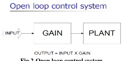
III. OPEN LOOP CONTROL OF DC MOTOR
As the name indicates, there is no feedback employed in this system. The duty cycle is given as the input to the system. The motor runs at a speed depending upon the duty cycle given as the input. The one of the digital output of the DAQ assistant is connected to the motor driver circuit and is always given as true so as to enable the motor.
Square wave with the specified duty cycle is generated in LabVIEW environment and is given to the DAQ assistant. The analog output pin of the DAQ is connected to the motor driver circuit. The motor ripple current is taken as the output by given appropriate rate and the number of samples.
Fig 2-Open loop control system
ISSN (Print) : 2320 – 3765 ISSN (Online): 2278 – 8875
I
nternational
J
ournal of
A
dvanced
R
esearch in
E
lectrical,
E
lectronics and
I
nstrumentation
E
ngineering
(An ISO 3297: 2007 Certified Organization)
Vol. 4, Issue 12, December 2015
L298 MOTOR DRIVER
It is a high voltage, high current dual full-bridge driver designed to accept standard TTL logic levels and drive
inductive loads such as relays, solenoids, DC and stepper motors. It works under the concept of H-Bridge. H-bridge is a circuit which allows current to be flown in both the directions.
Two enable inputs are provided to enable or disable the device independently of the input signals. An additional supply input is provided so that the logic works at a lower voltage.
Notations:
M1_IN (Motor 1 input connection)
M2_IN (Motor 2 input connection)
M1.EN (Motor 1 Enable pin)
M2.EN (Motor 2 Enable pin)
VCC (+5V) (myDAQ digital input)
GND (DGND)
+ (Supply Voltage) 5V battery
-(GND)
Fig-3 Motor driver circuit
Fig-3 shows a L298 motor driver circuit. We have to apply correct polarity to VCC and GND; otherwise it may damage the IC.
WORKING:
The connections are given as per the circuit diagram shown below.
A resistor is connected between the analog output voltage pins and analog ground. The resistor is used to produce the ripple current of a motor. MyDAQ analog output voltage pins AI0+, AI0- and AGND is given across the resistor. The motor driver circuit is given an external power supply for its working and MyDAQ is connected to the PC via USB cable.
Fig 4- Connection between myDAQ and motor driver circuit
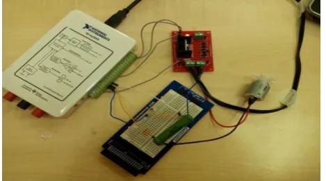
Fig 5-Interfacing myDAQ with computer
Fig-5 shows the image of interfacing myDAQ with computer. Interfacing of myDAQ with computer requires only a USB cable.
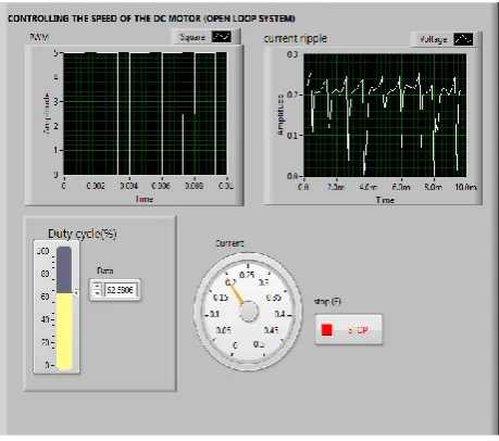
Fig 6- Front panel of open loop control of DC motor
The above figure (Fig-6) shows the front panel of the VI developed for open loop control system of the motor. As said earlier, duty cycle is given as the input to the system. The PWM and the ripple current are viewed with the help of a graph.The PWM signals has a fixed frequency and only the width of the pulses changes to alter the average power of the signal.As the changes are given in the duty cycle the ripple current also changes and is indicated in the gauge.
IV. CONTROLLING THE SPEED OF THE DC MOTOR USING FEEDBACK RIPPLE CURRENT
This method as the name indicates uses a feedback for controlling the speed of the motor (i.e.) closed loop control system is used. PID controllers are used from the control and simulation tool module to control the gain proportion.
ISSN (Print) : 2320 – 3765 ISSN (Online): 2278 – 8875
I
nternational
J
ournal of
A
dvanced
R
esearch in
E
lectrical,
E
lectronics and
I
nstrumentation
E
ngineering
(An ISO 3297: 2007 Certified Organization)
Vol. 4, Issue 12, December 2015
ripple current is to avoid the used of speed sensors for the motor. Capacitive type tachometer and encoders when used are cost wise not efficient. To avoid this constraint the ripple current is measured and it is given as the feedback to the system. Other options are frequency can also be used for providing the feedback.
Fig 7- Closed loop control system
Fig-7 shows the closed loop control system diagram. The input is given to the plant (process) via gain. The output of the process is taken as feedback for the system. The feedback may be either positive or negative. Negative feedback is generally used because positive feedback does not make the system stable.
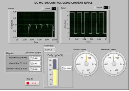
Fig 8-Closed loop controlling of DC motor.
Fig-8 shows the front panel of the controlling VI.It is seen from the VI that the PID gains and the desired gains are given and the feedback current is indicated. The desired duty cycle is given and the waveform for the given duty cycle is displayed.
WORKING:
When the duty cycle is changed the PWM width changes which in turn changes the speed of the motor. Desired current is given as the set point to the system. The feedback current is the process variable. Instead of manual control of the duty cycle, the controller output is given as the feedback in order to understand the working of closed loop DC motor speed control.
The PID values are tuned to track the set point given.
PID controls the gain portion of the closed loop control system.PID algorithms adjust the gain to the plant based on several characteristics of the feedback, not just the current value.
Fig 9-Closed loop control system with PID controller
The above diagram (Fig-9) shows the closed loop control system with a PID controller as the controller element. The difference between the input and the feedback produces error. The error is given as the input to the controller which produces the controller output which is proportional, integral and derivative of the error. The controller output is given to the plant or process to be controlled
V. RESULTS
The results obtained during the operation of the motor for both open loop and closed loop are tabulated below.
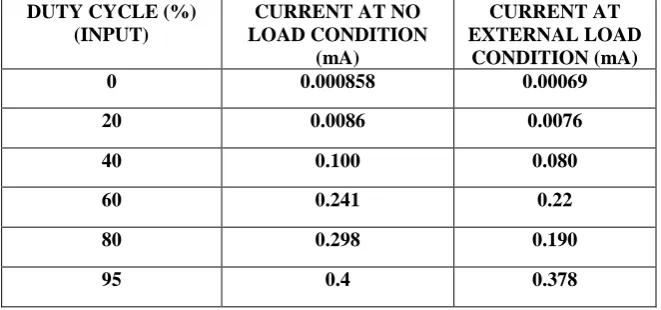
OPEN LOOP:
For the open loop control configuration, the following readings are obtained.
DUTY CYCLE (%) (INPUT)
CURRENT AT NO LOAD CONDITION
(mA)
CURRENT AT EXTERNAL LOAD
CONDITION (mA) 0 0.000858 0.00069 20 0.0086 0.0076 40 0.100 0.080 60 0.241 0.22 80 0.298 0.190 95 0.4 0.378
Table-1 Open loop configuration readings
ISSN (Print) : 2320 – 3765 ISSN (Online): 2278 – 8875
I
nternational
J
ournal of
A
dvanced
R
esearch in
E
lectrical,
E
lectronics and
I
nstrumentation
E
ngineering
(An ISO 3297: 2007 Certified Organization)
Vol. 4, Issue 12, December 2015
CLOSED LOOP:
For the closed loop control configuration, the following readings are obtained.
DESIRED CURRENT (SETPOINT) (mA)
DUTY CYCLE (%) (OUTPUT)
FEEDBACK CURRENT (mA)
(OUTPUT) 0.06 20 0.05 0.08 30 0.07 0.12 35 0.1 0.15 45 0.14 0.18 50 0.1798 0.21 60 0.20 0.24 65 0.23
Table-2 Closed loop configuration readings
In this control configuration, as seen earlier, the desired current must be given as the set point. Here the duty cycle need not be adjusted manually. As the set point is given and the PID gains are adjusted to a nominal value, the feedback current becomes almost equal to the set point and the motor runs with a duty cycle that has been automatically adjusted.
VI. CONCLUSION
This method serves to be a cost efficient method of controlling the speed of a dc motor since no speed sensors are used in this method.DC motor is controlled with the help of LabVIEW with myDAQ for data acquistion and generation purposes. Instead of sensors, ripple current is used for speed control operation.The speed control operation is performed both by open and closed loop configurations.The use of PID controller in LabVIEW also helps in controlling the speed of the motor more accurately and efficiently.
.
REFERENCES
1. Priyanka Rajput, “A Study of Speed Control of PMDC Motor using Auto-tuning of PID Controller through LabVIEW ", AKJEC International journal of Technology, Volume 5, No. 1,pp. 58-62,2014
2. Salim, Sunil Kumar, Jyoti Ohri "LabVIEW Based DC Motor and Temperature Control Using PID Controller " ,IJARCSSE, Volume 3, Issue-5,pp. 56-63, May 2013
3. Rinku Singhal, Subhransu Padhee, Gagandeep Kaur "Design of Fractional Order PID Controller for Speed Control of DC Motor ", International journal of Scientific and Research Publications, Volume 2, Issue 6,pp. 1-8, June 2012,
4. Megha Jaiswal , Mohna Phadnis "Speed Control of DC Motor Using Genetic Algorithm Based PID Controller", IJARCSSE, Volume 3, Issue 7,pp. 247-253, July 2013