IJEDR1604019
International Journal of Engineering Development and Research (www.ijedr.org)105
Analysis Of Thermal Energy Storage In Different
Applications By Using Phase Change Materials
A Review
1Apurav S. Joshi, 2Suprabhat A. Mohod, 3Manoj Dhawade 1Student, 2Asst. Professor, 3Asst. Professor
1 Department of Mechanical Engineering,
1Lokmanya Tilak College of Engineering, Koparkhairane, Navi Mumbai, India
________________________________________________________________________________________________________
Abstract: In earlier time, the available heat has been stored in the form of sensible heat storage, normally by raising the
temperature of rock, water, etc. But in recent time Thermal energy storage (TES) can be achieved with the help of Phase change material (PCM) as a latent heat storage which results in smaller temperature fluctuations, lower weight per unit storage capacity & are smaller in size. This paper reviews the use of PCM for different applications such as solar air heater, refrigeration, water heating system & building applications. It was found that with the help of HS-58 as a PCM in solar air heater can store more energy during peak hours & increases the duration of utilization after the sunshine. The effect of PCM panel placed inside the wall of the freezer during repeated power loss & it was observed that freezer containing PCM shows lower temperature variation than without PCM. Experimental analysis of PCM based storage system for better water heating at night shows that there was 12-16% increase in the temperature of hot water by using PCM as compared to without PCM. With the aid of PCM, indoor temperature of building can be controlled which not only provide thermal comfort but also reduce the energy consumption up to 30-40% for the same requirement. Results were calculated based on their performances.
Keyword: Thermal energy storage, latent heat storage, phase change material
________________________________________________________________________________________________________
I.INTRODUCTION
Thermal energy storage (TES) refers to the technology that allows the transfer and storage of heat energy or alternatively. It is used to store heat energy when there is no demand & supplies the heat energy when there is a demand. Thermal energy storage is necessary in application where there is a temporal lag between the supply & demand of the energy. It mainly involves three steps that are, charging, storage & discharging, giving a complete storage cycles. TES systems have the probably for growing the effective use of thermal energy instrumentality and for facilitating large-scale fuel commutating. The selection of a TES system for a specific application depends on several factors like storage power, storage length, utilization temperature necessities, and economics and heat losses. The different types of thermal energy storage are sensible and latent. Sensible TES systems store energy by dynamic the temperature of the storage means that, which may be brine, water, soil, rock, etc. Latent TES systems store energy through phase change, e.g., warmth storage by melting paraffin waxes & cold storage water/ice. Latent TES units are typically smaller than sensible storage units. TES is now becoming a significant aspect & expected to be utilized on large scale in different fields are as follow:
1. Cold storage in buildings
2. Cold storage in industrial appliances 3. Domestics hot water (Buffer storage )
4. Waste heat ( cement ,steel & glass industries )
5. High temperature storage (more than 400°C) for concentrated solar power system
IJEDR1604019
International Journal of Engineering Development and Research (www.ijedr.org)106
II. TYPES OF TES SYSTEM1. Sensible heat storage :
In this type of storage system, energy is stored or obtained by heating or cooling a solid or a liquid, which doesn’t change its phase during the process. Different types of substances have been used in such system .These includes liquid like water ,heat transfer oil ,certain inorganic molten salts & soil like ,rocks pebbles & refractory. The selection of material is based on the temperature level of the application. Water is being used for temperature below 100°C, while refractory bricks are used for temperature around 1000°C.Sensible heat storage are simpler in design, however they can’t provide delivery of energy at constant temperature and also they are of bigger sizes.
Phase Medium Temperature range (°C) Density (Kg/m3) Specific heat (J/Kg.K)
Solid
Rock 7-27 2560 879
Brick 17-37 1600 840
Concrete 7-27 2101 880
Sand 7-27 1550 800
Soil 7-27 2041 1840
Liquid
Water 7-97 1000 4180
Engine oil Up to 157 888 1880
Ethanol Up to 77 790 2400
Butanol Up to 118 809 2400
Other organic Up to 420 800 2300
Table 1 –Materials for sensible heat storage
2. TES via Chemical reaction :
This type of system also known as Bond storage as if system composed of one or more chemical compound that absorb or release energy through bond reaction (reversible reaction ). It can be explained by following example
A+B AB + DH (heat is released) AB+DH (heat is consumed) A +B
If we bring chemical compound A & B, it will liberate some amount of heat energy & formation of product AB compound take place. This heat energy is then stored or utilized by the application. Further chemical compound AB consumes some amount of energy & compound A & B will get separated by controlled chemical reaction. Using TCS we can achieve high energy density up to 300KJ/m3 .It has an adequate capacity & efficiency compared to other systems.
Sr. No
Thermochemical material
Solid reactant
Working fluid
Energy storage density of thermochemical material (GJ/m3 )
Charging reaction temperature (°C)
1 MgSO4·7H2O MgSO4 7H2O 2.8 122
2 FeCO3 FeO CO2 2.6 180
3 Fe(OH)2 FeO H2O 2.2 150
4 CaSO4·2H2O CaSO4 2H2O 1.4 89
Table 2- Chemical reaction for TES
3. TES via PCM (Phase change material)/Latent heat storage :
In PCM, principle behind that is, when heat is supplied to material it changes its phase from solid to
IJEDR1604019
International Journal of Engineering Development and Research (www.ijedr.org)107
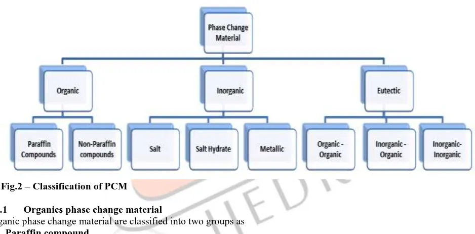
3.1 Classification of PCMA large number of phase change material are available in any required temperature range. Classification of PCM is given in Fig.2
Fig.2 – Classification of PCM
3.1.1 Organics phase change material
Organic phase change material are classified into two groups as 1) Paraffin compound
Paraffin wax is a mixture of usually straight chain n-alkanes CH3–(CH2)–CH3. The crystallization of the (CH3) - chain release a very large amount of latent heat energy. As the chain length increases both melting point & latent heat of fusion also increase. Due to availability in large temperature range Paraffin qualifies as a heat of fusion storage material. They are chemically stable below 500°C.
Sr. No Paraffin Freezing point (°C) Heat of fusion (kJ/Kg)
1 6499 66–68 189
2 5838 48–50 189
3 P116 45–48 210
4 6035 58–60 189
5 6106 42–44 189
Table 3- Physical properties of some paraffin’s 2) Non-paraffin compound
The non-paraffin organic has the various phase change materials with highly varied properties. These materials are ignitable and it should not be exposed to excessively high temperature, flames or oxidizing agents. Each of these materials will have its own properties contradictory to the paraffin’s, which have very similar properties. Some of the properties are listed below,
(i) Varying level of toxicity (ii) High heat of fusion (iii) low flash points
IJEDR1604019
International Journal of Engineering Development and Research (www.ijedr.org)108
(v) inflammability(vi) Instability at high temperatures
Sr. No Material Melting point(°C) Latent heat (kJ/Kg)
1 Formic acid 7.8 247
2 Methyl palmitate 29 205
3 Caprilic acid 16.3 149
4 Glycerin 17.9 198.7
5 Glycolic acid 63 109
Table 4 – Physical properties of some non-paraffin compounds
3.1.2 Inorganic compound
Inorganic compound are again classified as salts, salt hydrate, metallic. Their heat of fusion does not degrade with cycling & they do not supercool appreciably. Salt hydrates may be referred as alloys of inorganic salts and water forming a typical crystalline solid of general formulaABnH2O. The properties of salt hydrate are, relatively high thermal conductivity (almost double of the paraffin’s), High latent heat of fusion per unit volume and small volume changes on melting. They are compatible with plastics and only slightly toxic & also they are not very corrosive. Metallic includes low melting metal & metal eutectics. These metallic are rarely used for PCM technology because of weight penalties. Some of the properties of metallic are high thermal conductivity, low heat of fusion per unit weight, low specific heat, high heat of fusion per unit volume, relatively low vapor pressure.
Sr. No Material Material type Melting point(°C) Latent heat (kJ/Kg)
1 K2HPO4.6H2O Salt hydrate 14.0 109
2 Mn(NO3)2.6H2O Salt hydrate 25.5 148
3 LiNO3.2H2O Salt hydrate 30.0 296
4 Cerrobend eutectic Eutectic 70 32.6
5 Gallium Eutectic 30.0 80.3
6 Cerrolow eutectic Eutectic 58 90.9
Table 5-Physical properties of some inorganic compound
3.1.3 Eutectic
It is a minimum-melting composition of two or more components, each of which melts and freeze congruently forming mixtures of the component crystals during crystallization. It nearly always melts and freezes without segregation since they freeze to intimating mixtures of crystals, leaving little opportunity for the components to separate. They have sharp melting point also volumetric storage density is slightly above the organic compounds. But the main disadvantage is about these compound is only limited physical available on thermo-physical properties as the use of these materials relatively new to the thermal storage system.
Sr. No PCM Melting point(°C) Latent heat (kJ/Kg) Density(Kg/m3)
1 H300 302 130 1900
2 H395 395 215 2330
3 H430 430 125 2160
4 H500 500 300 2220
5 H535 535 130 2320
6 H610 610 410 2070
7 H650 652 300 2450
Table 6- Commercially available PCM’s
III. REVIEW OF SOME RESEARCHERS
3.1 Esakkimuthu et al. [1]
IJEDR1604019
International Journal of Engineering Development and Research (www.ijedr.org)109
3.1.1 Material specification:1. Centrifugal blower
2. Cylinder shaped packed bed type PCM (HS-58)
3. Solar air collector (Dimensions 2mX1m,Total area 6m2,Transperent area 5.67m2)
3.1.2 Experimental procedure:
When charging process is initiated air is sucked from the atmosphere & this air is then heated by solar radiations. Also additional heat is provided with the help of finned electric heaters which is fitted inside the insulated enclosure after the blower. Now this air is then pass through the TES tank & PCM will absorb heat energy & will change its phase from solid to liquid. The charging observations are performed by supplying heated air at 70°C to the drier unit. While in discharging process, the observations are carried out by supplying ambient air at the inlet. For charging & discharging process different mass flow rates are used & pressure drop across each mass flow rate of packed bed is noted. Further inlet and outlet temperature of air in the PCM is noted & experiment is conducted several times to check the correctness of readings.
3.1.3Result & conclusion:
Using HS-58 as a PCM in latent heat storage unit integrated with solar air heater to store more energy during peak hours & increase the duration of utilization of heater after the sunshine hours is studied experimentally for different mass flow rates. At greater mass flow rates the efficiency of collector is also high which reduces the heat loss related with the decrease in average temperature of collector. It is noticed that the mass flow rate of 200Kg/hr. is able to give a near uniform rate of heat transfer during charging & discharging process. At lower mass flow rate is able to provide maximum capacity of the storage system & supply heat for longer duration.
3.2 Gin et al. [2]
In this paper, researcher have studied the effect of phase change material panels (aqueous ammonium chloride solution) placed inside the wall of the freezer during repeated power loss of every 24 hours over two week period. Observations are made over the air temperature & product temperature in the freezer. Freezer containing PCM panels showed lower temperature variation than in a freezer without PCM. Different product are observed like, 1x1 cm cubes of bovine muscles ,ice crystal of 1L vanilla ice-cream & meat etc.
Fig. 3 –Variation in product temperature during 3 hour power loss [2] 3.2.1 Result & conclusion:
During power loss, PCM helps to lower the rate of temperature increase in freezer as compared to without PCM. It was observed that without using PCM, a 3 hour power loss leads to temperature -3°C,whereas with the help of PCM
-5°C is reached in the freezer. Therefore it can be conclude that lower temperature variation can be achieved with the help of PCM, which led to better quality of frozen food.
IJEDR1604019
International Journal of Engineering Development and Research (www.ijedr.org)110
Researcher had presented an experimental analysis of PCM based storage system for better water heating at night & results were concluded. Here water is used as a heat transfer fluid & CaCl2.6H2O is used as a PCM in the experiment. The temperature variations of HTF (Heat transfer fluid) with and without PCM in the TES tank for same mass flow rate were recorded during charging and discharging processes. Also they have studied temperature variation of HTF vs time, efficiency of collector vs time & thermal performance of CaCl2.6H2O (calcium chloride hexahydrate) by using as a PCM based TES for heating the cold water on the concept of night or free heating.3.3.1 Material specification: 1. Parabolic collector 2. Water supply tank
3. Thermal energy storage tank with PCM (CaCl2.6H2O) 4. Pyrometer
5. Rotameter 6. Thermocouple
3.3.2 Experimental procedure:
During charging process, the HTF was supplied from water supply tank & then circulated through solar parabolic plate collector and TES storage tank. When the flow of water was started, it will pass through the rotameter & the collector with a rate of 10 LPH, which will heat the HTF. Now this heat is absorbed by the PCM storage tank. During discharging process (at night time) the PCM release heat & this heat is absorbed by the water inside the storage tank. Due to this investigation we can obtain hot water up to temperature of 45°C at night. This investigation was carried out with and without PCM.
3.3.3 Result & conclusion:
Results were compared for the same capacity of solar parabolic collector with and without PCM. An investigation result shows that the temperature of HTF (from 6 to 9 pm) with PCM is comparatively more than the temperature of HTF without PCM. It shows that it is feasible and advantageous to use this system for industrial purpose, domestic use, hotel, etc. which shows nearly 12 – 16% increase in the temperature of hot water by using with PCM as compared to without PCM. Thus system is not affected by the load shading in rural areas of India & hence it reduces the consumption of conventional energy.
3.4 Waqas et al. [4]
Researcher had studied about the free cooling of the building with help of PCM. It was observed that buildings are responsible for 40% of the world annual energy consumption which is subjected to one third of greenhouse gases in the world. A momentous portion of this energy can be used for different purposes like heating, cooling & air conditioning in the buildings. To cut down this increasing production of greenhouse gases, a selection of PCM based technology should be incorporated.
3.4.1 Result & conclusion:
With the help of PCM, it is expected that the energy consumption & cost for same requirement is reduced by 30-40% in the building. By adopting PCM based technology in different parts of building likes, window, wall, roof, floor, etc. which control the indoor temperature & provide thermal comfort. Further if such system were used rather than conventional ventilation and air conditioning systems, which not only reduces electric consumption but also reduces the GHG (Green house gases) and CFC (Chlorofluorocarbon) emissions.
CONCLUSION
After comprehensive study of TES (Thermal energy storage) system with different PCM (Phase Change Material) for different applications, it can be concluded that there is need of precise research in this zone. After implementing TES the benefits are better economics i.e. It will reduce capital & operational cost, efficient use of energy can be achieved with good system performance & reliability. It was observed that there is reduction of 30-40% for same kind of energy requirement. Also it will less pollute the environment & CO2 emission can be reduced. In future, PCM will be greatly incorporated in every application as low environmental impact technologies.
REFERENCES
[1] S. Esakkimuthu , Abdel Hakim Hassabou , C. Palaniappan , Markus Spinnler , Jurgen Blumenberg , R. Velraj, “Experimental investigation on phase change material based thermal energy storage system for solar air heating applications”, Solar Energy 88 (2013) 144–153
[2] B. Gin, MM farid & P.K. Bansal (2010),”Effect of door opening & defrost cycle on a freezer with phase change panels”. Energy conversion & management, 51, 2698-2706.
[3] S.A.Mohod, S.R.Karale, “Analysis of PCM based storage system in an improvement for water heating systems”, International Journal of Advance Research In Science And Engineering, Vol. No.3, Issue No.5, May 2014
[4] Adeel Waqas , Zia Ud Din, “Phase change material (PCM) storage for free cooling of building – a review”, Renewable and Sustainable Energy Reviews 18 (2013) 607–625
IJEDR1604019
International Journal of Engineering Development and Research (www.ijedr.org)111
[6] Francesco Guarinoa, Vasken Dermardirosb, Yuxiang Chenb, Jiwu Raob, Andreas Athienitisb, Maurizio Celluraa, MarinaMistrettac, “PCM thermal energy storage in buildings: experimental study and applications”, Energy Procedia 70 ( 2015 ) 219 – 228
[7] Abhay B. Lingayat, Yogesh R. Suple, ”Review On Phase Change Material As Thermal Energy Storage Medium: Materials, Application”, ISSN: 2248-9622 www.ijera.com Vol. 3, Issue 4, Jul-Aug 2013, pp.916 921
[8] S.M.Hasnain, “Review on sustainable thermal energy storage technologies part I: Heat storage material & techniques”, Energy Convers. Mgmt. Vol. 39, No. 11, pp. 1127-1138, 1998
[9] Belen Zalba, Jose Ma Marın, Luisa F. Cabeza,Harald Mehling, “Review on thermal energy storage with phase Change: materials, heat transfer analysis and applications”, Applied Thermal Engineering 23 (2003) 251–283
[10]M .Ravikumar, DR. PSS. Srinivasan, “Phase change material as a thermal energy Storage material for cooling of building”, Journal of Theoretical and Applied Information Technology