Article
1
Multi-Rate Real-Time Simulation Method Based on
2
the Norton Equivalent
3
Junjie Zhu*, Bingda Zhang
4
The Key Laboratory of Smart Grid of Ministry of Education, Tianjin University, Tianjin 300072, China;
5
[email protected] (J.Z.); [email protected] (B.Z.);
6
* Correspondence: [email protected]; Tel.: +86-182-2206-9101
7
Abstract: For the problem of poor accuracy of the existing multi-rate simulation methods, this paper
8
proposes a multi rate real-time simulation method based on the Norton equivalent, compared with
9
multi-rate simulation method based on the ideal source equivalent. After the Norton equivalence of
10
the fast subsystem and the slow subsystem, they are obtained simultaneously at the junction nodes.
11
In order to reduce the amount of simulation calculation, the Norton equivalent circuit is obtained
12
by incremental calculation. The data interface between the fast subsystem and the slow subsystem
13
is realized by extrapolation method. For ensuring the real-time performance of the simulation, the
14
method that the slow subsystem calculates ahead of the fast subsystem is given for the slow
15
subsystem with a large amount of calculation. Finally, the AC/DC hybrid power system was
16
simulated on the real-time simulation platform (FRTDS), and the simulation results were compared
17
with the single-rate simulation, which verified the correctness and accuracy of the method.
18
Keywords: multi-rate real-time simulation; the ideal source equivalent; the Norton equivalent;
19
increment; extrapolation method
20
21
1. Introduction
22
China has built the world's largest AC/DC hybrid power system with the highest voltage level,
23
and the regional power grids have been interconnected through Ultra-high voltage AC / DC
24
transmission lines [1,2]. The control and protection system plays an important role in the safe and
25
reliable operation of AC/DC hybrid power system, and the real-time simulation technology based on
26
hardware in the loop can be used to verify the correctness of the protection device action and the
27
effectiveness of the control strategy [3,4].
28
Large-scale AC/DC hybrid power system contain a large number of power electronic devices.
29
Compared with traditional AC power system, these devices have a small time scale, and their
30
dynamic characteristics have a great impact on the safe and stable operation of the power system. In
31
order to simulate power electronic equipment more accurately, the simulation step size is required
32
to be smaller and smaller [5]. This is a challenge for the simulation of AC/DC hybrid power system.
33
For improving the speed of simulation, two aspects are generally considered, one is to reduce the
34
amount of simulation calculation, the other is to use parallel computing technology. Ref [6] proposed
35
a multi-layer topology hybrid model for power electronic switching components, which allows a
36
large number of single switches to be reduced to only two diodes and controlled voltage and current
37
sources. This greatly reduces the number of switching combinations and the size of the generated
38
code, and improves the speed of simulation. Ref [7] proposed a method of GPU based parallel matrix
39
exponential algorithm for large scale power system electromagnetic transient simulation, which
40
significantly improves the simulation calculation speed. However, the GPU cannot independently
41
complete the process control and data scheduling in the simulation calculation process, so it needs to
42
cooperate with the CPU to complete the simulation calculation [8]. The above methods are all
single-43
rate electromagnetic transient simulation methods, ignoring the differences in the time scale of power
44
equipment in different systems. The selection of simulation step size can only be based on the system
45
with the smallest time scale of power equipment, which will cause serious waste of computing
46
resources. [9].
47
In view of the above problems, scholars at home and abroad have proposed the concept of
48
parallel multi-rate electromagnetic transient computing, and different simulation steps are adopted
49
for different systems according to the time scale of power equipment in the system [10–12]. Ref [13]
50
proposed a multi-rate electromagnetic transient simulation method based on Latency technology, in
51
which the external part of the subnet was modeled as an ideal source. As the ideal source model
52
could not guarantee that the node signals (voltage and current) on both sides of the interface were
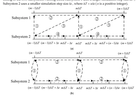
53
equal, the simulation accuracy was reduced. Ref [14] proposed a node splitting interface (NSI)
multi-54
rate parallel technology. It solves the state space equations of fast and slow subnets simultaneously,
55
avoiding data prediction and signal delay, and improving the simulation accuracy, but the method
56
cannot be used for real-time simulation. The above multi-rate simulations are all offline simulations
57
and cannot be used for hardware-in-the-loop experiments. Ref [15] proposed a multi-rate real-time
58
simulation method based on a joint simulation platform of real-time digital simulator (RTDS) and
59
field programmable gate array (FPGA). It uses the asynchronous interaction method that FPGA data
60
transmission is appropriately earlier than RTDS data transmission, which reduces a certain
61
communication delay. But the communication delay problem of data interaction between different
62
platforms still exists, which causes the reduction of simulation accuracy. In Ref [16] a FPGA based
63
MR real-time simulation of MMC-HVDC grids is proposed. The MMC system is decoupled by a
stub-64
line, and each MMC valve is implemented on one FPGA. The FPGAs can select different time steps
65
to meet the requirement of the time constraints. However, using multiple FPGA blocks for simulation
66
calculation will not only cause data synchronization problem and decrease the simulation accuracy,
67
but also waste the hardware resources of FPGA.
68
For the problem of poor accuracy of the existing multi-rate simulation methods, this paper
69
proposes a multi rate real-time simulation method with the Norton equivalent circuit based on
multi-70
rate simulation method with the ideal source equivalent. After the Norton equivalence of the fast
71
subsystem and the slow subsystem, they are obtained simultaneously at the junction nodes. In order
72
to reduce the amount of simulation calculation, the Norton equivalent circuit is obtained by
73
incremental calculation. The data interface between the fast subsystem and the slow subsystem is
74
realized by extrapolation method. Finally, the AC/DC hybrid power system was simulated on the
75
real-time simulation platform (FRTDS), which verified the correctness and accuracy of the method.
76
2. Multi-rate Simulation Calculation Timing
77
In the AC/DC hybrid power system, the power electronic equipment with fast control
78
characteristics and the AC large-scale power grid are intertwined in different time scale processes,
79
which makes the operation and control characteristics of the AC/DC hybrid power system more
80
complicated [17]. Therefore, in the simulation of the AC/DC hybrid power system, various time scale
81
processes in the AC/DC hybrid power grid should be considered. The simulation must be able to
82
simulate the fast electromagnetic transient process (time scale of a few microseconds) of power
83
electronic equipment such as converters and static synchronous compensators. It is also necessary to
84
be able to simulate the switching process of the converter valve of the DC power system and the
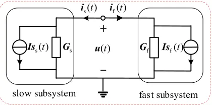
85
electromagnetic transient process of the AC power system (time scale of tens of microseconds to
86
hundreds of microseconds) [18,19]. When using a single simulation step to simulate an AC/DC hybrid
87
power system. If the simulation step is too small, the amount of calculation that needs to be completed
88
within a single step is too large to complete. If the simulation step size is too large, the dynamic
89
characteristics of the power electronic components cannot be simulated, which reduces the accuracy
90
of the simulation. For balancing the accuracy of simulation and the scale of simulation, the entire
91
system is decomposed into multiple subsystems. According to the time scale of the power equipment
92
in the subsystem, different step sizes are used for simulation calculation, that is, multi-rate
93
simulation.
94
There are two types of multi-rate simulation calculation timing: serial calculation timing and
95
timing of the two subsystems. Among them, Subsystem 1 uses a larger simulation step sizeT, and
97
Subsystem 2 uses a smaller simulation step sizet, whereT n t(nis a positive integer).
98
Subsystem 1
m T
(m 1) T (m 1) T
(m 1) T (m 1) T t m T t m T m T t m T (n 1) t (m 1) T
Subsystem 2
1
2
3
4
1
2
3
4
99
(a)
100
m T
(m 1) T (m 1) T
(m 1) T (m 1) T t m T t m T m T t m T (n 1) t (m 1) T
1
2
2
2
2
1
1
Subsystem 1
Subsystem 2
101
(b)
102
Figure 1. Simulation calculation timing. (a) Serial calculation timing. (b) Parallel computing timing
103
In multi-rate simulation, the calculation tasks of serial calculation timing need to be completed
104
in sequence. In Figure 1(a),
○
1 at the time of(m 1) T, subsystem 2 transmits the data to subsystem 1105
through the interface;
○
2 Subsystem 1 uses the received data for simulation calculation;○
3106
Subsystem 1 transfers the data to Subsystem 2 through the interface;
○
4 Subsystem 2 uses the107
received data for simulation calculation. In serial calculation, the calculation tasks
○
1 ,○
2 ,○
3 and○
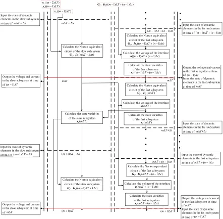
4108
need to be completed in sequence, which seriously affects the speed of simulation calculation.
109
Therefore, the serial calculation sequence can generally only be used for offline simulation, not for
110
real-time simulation calculation.
111
The task of parallel computing time sequence can be completed at the same time, which
112
improves the computing speed. In Figure 1(b),
○
1 at the time of(m 1) T , subsystem 1 and113
Subsystem 2 conduct data interaction;
○
2 Subsystem 1 uses the received data for one simulation114
calculation, while subsystem 2 uses the received data for n times of simulation calculation. In
115
Subsystem 2, the data required by the simulation calculation is not known and more prediction data
116
is required, so the parallel multi-rate simulation accuracy is low. However, for ensuring the real-time
117
nature of multi-rate simulation, only parallel calculation timing can be used.
118
3. Multi-rate real-time simulation based on the Norton equivalence
119
3.1.Multi-rate Real-time simulation method based on the ideal source equivalence
120
In the multi-rate real-time simulation of the power system, the inductance and capacitor element
121
can be equivalent to the ideal source and the system is decoupled into multiple independent
122
subsystems by taking advantage of the fact that the inductance current and capacitance voltage in the
123
circuit cannot be suddenly changed. For example, the circuit with inductance L is equivalent as
124
-1( )
i t i t2( )
+
-+
1( )
u t u t2( )
+ i tL( )
-Subsystem 2 Subsystem 1
L
+
-
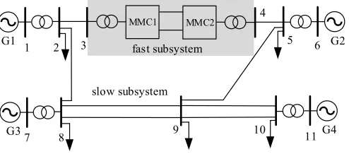
-+ 2( )
i t
1( )
i t
1( )
u t u t2( ) Subsystem 2
Subsystem 1
126
(a) The original circuit (b) The equivalent circuit
127
Figure 2. The equivalent diagram of capacitor branch.i tL( )is the current with inductance L.u t1( ),u t2( )is the
128
voltage across the inductance L. At this time, the inductance L is equivalent to an ideal current source, and the
129
system is decoupled into two independent subsystems, as shown in Figure 2(b).
130
The relationship between currenti tL( )and voltageu t1( ),u t2( )with inductance L is as follows in
131
Fig. 2(a).
132
1( ) 2( ) L di u t u t L
dt
= (1)
133
Assuming that Subsystem 1 uses a larger simulation step sizeT , and Subsystem 2 uses a
134
smaller simulation step size t, whereT n t (
n
is a positive integer). By using Euler method to135
differentiate equation 1, then we can find:
136
1 2
1
1
( ) ( ) [ ( ) ( )]
n L L
k
T
i t i t T u t u t T k t
L n
(2)137
At the time ofm T , Subsystem 1 and Subsystem 2 exchange and synchronize information. The
138
voltageu t1( )andu t1( T)of Subsystem 1 is sent to Subsystem 2, and the voltageu t2( T k t)
139
(k=1,2,…,n)of Subsystem 2 is sent to Subsystem 1. Then perform data synchronization according to
140
the substitution theorem, namelyi t1( )=i t2( )=i tL( ).After that, the calculation can be divided into two
141
parallel tasks. The voltage and current of the equivalent current source of Subsystem 1 and Subsystem
142
2 are obtained simultaneously.
143
For Subsystem 1, the current i t1( T)of the equivalent current source can be represented as:
144
1( ) 1( ) [ ( )1 2( )]
T
i t T i t u t u t L
(3)
145
According to the currenti t1( T)of Subsystem 1, calculate the voltageu t1( T)of Subsystem 1.
146
For subsystem 2, the currenti t2( k t)of the equivalent current source can be represented as:
147
2( ) 2( ( 1) ) [ 1( ( 1) ) 2( ( 1) )] t
i t k t i t k t u t k t u t k t L
(4)
148
Whereu t2( (k 1) t)andi t2( (k 1) t)are the voltage and current of the equivalent current source
149
in Subsystem 2 and they are known. However, the currentu t1( (k 1) t)in Subsystem 1 is unknown,
150
and it can be estimated by extrapolation. Then the extrapolation formula is:
151
1 1 1 1
1
( ( 1) ) ( ) k [ ( ) ( )]
u t k t u t u t u t T n
= (5)
152
According to the currenti t2( k t)of Subsystem 2, calculate the voltageu t2( k t)of Subsystem 2.
153
After that, the simulation of the next moment will be continued. Similarly, the calculation
154
process of multi-rate simulation method with capacitor C can be obtained. The multi-rate simulation
155
method with the ideal source equivalence takes advantage of the fact that the state variables of the
156
inductors and capacitors in the system can not be changed suddenly, and they are equivalent to the
157
ideal source model. Then, the whole system is decoupled by substitution theorem. However, in the
158
simulation calculation, the voltage and current of the ideal source are all predicted, so the accuracy
159
of this method is very low.
160
3.2.Multi-rate Real-time simulation method based on the Norton equivalence
161
For the problem of the accuracy with the ideal source equivalent method, the idea of the Norton
162
equivalent is used to replace the ideal source equivalent . After the Norton equivalence of the fast
163
subsystem and the slow subsystem, they are obtained simultaneously at the junction nodes, and then
164
There are two linear sources-containing subsystems. A subsystem has a small time scale,
166
represented by the subscript f. The other subsystem has a larger time scale, denoted by subscript s.
167
The two subsystems are connected to each other through k nodes, as shown in Figure 3.
168
slow subsystem
…
…
…
…
…
f 1
i
f 2
i
fk
i
s1
i
s 2
i
sk
i
1
u
u
2u
kL
C R
fint i
fast subsystem L
C R
sint
i
169
Figure 3. The diagram of power system. The input of the slow subsystem and the fast subsystem consists of two
170
parts, the independent current source inside thesubsystem, and the voltage or current at the interface. Whereis
171
andifare the current vectors at the subsystem interface;uis the voltage vector at the subsystem interface;isint
172
andifintare the independent current source vectors inside the subsystem.
173
The Norton equivalent is applied to the slow subsystem and the fast subsystem, and the
174
simulation diagram based on the Norton equivalent is as shown in Figure 4.
175
s( )
Is t
slow subsystem
+
-f( )
Is t
s( )
i t i tf( )
( )
u t
fast subsystem s
G Gf
176
Figure 4. Simulation diagram based on the Norton equivalent circuit
177
Assuming that the slow subsystem uses a larger simulation step sizeT, and the fast subsystem
178
uses a smaller simulation step sizet, whereT n t(
n
is a positive integer). The Norton equivalent179
circuit of the slow subsystem and the fast subsystem can be expressed as:
180
s( ) s ( ) s( )
i t G ut Is t (6)
181
f( ) f ( ) f( )
i t G ut Is t (7)
182
Where,i ts( )andi tf( )are the current vectors at the Norton equivalent circuit interface;u t( )are the
183
voltage vector at the Norton equivalent circuit interface;GsandGfare the admittance matrix of the
184
Norton equivalent circuit, which are related to the state of dynamic elements in the slow subsystem
185
and the fast subsystem.Is ts( )andIs tf( )are the current sources of the Norton equivalent circuit, and
186
they are linear combinations of individual current sources and historical current sources.
187
So the current sources of the Norton equivalent circuit Is ts( )andIs tf( )can be represented as:
188
s( ) s s( ) s sint( )
Is t C x t T D i t (8)
189
f( ) f f( ) f fint( )
Is t C x t t D i t (9)
190
Where,x ts( T)andx tf( t)are the state variables at the previous moment in the slow subsystem
191
and the fast subsystem.isint( )t andifint( )t are the independent current sources at the moment in the
192
slow subsystem and the fast subsystem.Cs,Ds,CfandDfare the parameter matrix.
193
On the interface between the slow subsystem and the fast subsystem, there is:
194
s( ) f( )
i t i t (10)
195
From formula (6), (7) and (10), we can find:
196
s f s f
(G G u) ( )t [Is( )t Is( )]t (11)
197
Where equation (11) is called the voltage equation of the interface node. From equation (11), the
198
voltage vector of the interface between the slow subsystem and the fast subsystem is obtained. After
199
When tm T (mis a positive integer), the state of each dynamic element in the two subsystems
201
and the state variablesx m Ts( T)andx m Tf( t)at the previous moment of the two subsystem
202
are known. Then the Norton equivalent is applied to the two subsystems, and calculateGs,Is ts( ),Gf
203
andIs tf( ). The voltage of the interface node can be obtained by the equation (11). Finally, the state
204
variables of the whole network is obtained.
205
When tm T k t(k=1,2,…,n-1), the state of each dynamic element in the two subsystems and
206
the state variables xf(m T (k 1) t)at the previous moment of the fast subsystem are known.
207
However, the state variables xs(m T T k t) of the slow subsystem are unknown. We can
208
calculate it as followed by extrapolation.
209
s( ) s( ) [ s( ) s( )]
k
m T T k t m T m T m T T
n
x =x x x (12)
210
For the slow subsystem, the parameter matrixGscorresponds to the state of the dynamic
211
element at time of (m1)T k ttom T k t, which spans two periods. For simplifying the
212
calculation, the dynamic element state at timem T is used to solve the Norton equivalent of the
213
slow subsystem, namelyGs(m T k t)=Gs(m T ). When solving the current sources of the Norton
214
equivalent circuit, for reducing the amount of calculation, the current sourcesIs m Ts( k t) is
215
obtained by interpolation throughisint(m T ) and isint(m T T) , instead ofisint(m T k t) . the
216
current sourcesIs m Ts( k t)can be expressed as:
217
s( ) s( ) s( )
Is m T k t Is m T kIs m T (13)
218
Where the increment of equivalent current sourceIss(m T )can be represented as:
219
s s s s 2 s sint sint
1
(m T) { [ (m T T) (m T T)] [ (m T T) (m T)]}
n
Is C x x D i i (14)
220
It is obvious that the current source of the Norton equivalent circuit only need be calculated once in
221
a large simulation step size, and the remaining current source can be obtained by the increment of
222
equivalent current source. Therefore, does not need to use parameter matrix frequently calculate
223
them, which greatly reduces the amount of calculation.
224
It can be seen from the previous analysis that the solution of the voltage equation with the
225
interface node requires the Norton equivalent of the fast subsystem and the slow subsystem.
226
Therefore, the conductance and current source with the Norton equivalent of the slow subsystem
227
need to be sent to the fast subsystem to solve the node voltage of the interface. After the node voltage
228
of the interface is solved, it needs to be sent to the slow subsystem to solve the internal state variables.
229
Whent m T= , summarizing the above solution process, the process of the multi-rate real-time
230
simulation method based on the Norton equivalent is as follows:
231
(1) Calculate the Norton equivalent circuit of the slow subsystem and the fast subsystem at the
232
kth (k=0,1,2,…,n-1),period.
233
s s s s sint
s s s
( Δ ) ( Δ ) ( 0
( Δ ) ( ) ( )
) 0
Is C D
Is Is Is
x i
t k t t T t k =
t k t t k t k
(15)
234
f( Δ ) f f( ( 1)Δ ) f fint( Δ )
Is tk t C x t k t D i tk t (16)
235
(2) According toGs,Gf,Is ts( k tΔ )andIs tf( k tΔ ), write the voltage equation of the interface
236
node.
237
s f s f
(G G u) (tk tΔ ) [Is(tk tΔ )Is(tk tΔ )] (17)
238
(3) Solve the voltage equation of the interface node to get the voltage of the interface node
239
( Δ )
u tk t .
240
(4) According tou t( k tΔ ), the state variablex tf( k t)of the fast subsystem can be obtained,
241
and the state variablex ts( )of the slow subsystem also can be obtained.
242
3.3. Thedata interactionofmulti-rate simulation.
243
For hardware-in-the-loop simulation, all calculations of a step size must be completed within
244
multi-rate real-time simulation method based on the Norton equivalent, the Norton equivalent circuit
246
parameters of the slow subsystem and the fast subsystem are used to solve the voltage of interface
247
node. However, compared with the fast subsystem, there are many nodes the slow subsystem. The
248
calculation amount of solving the Norton equivalent circuit is very large, and it is difficult to complete
249
in a small step size. Since the slow subsystem is an AC power system, it is not very important for the
250
moment of state change of dynamic elements. In order not to delay the solution of the interface node
251
voltage, the calculation of the slow subsystem can beearlier than the fast subsystem. For the timeS
252
of the earlier solving the slow subsystem, it can be assumed that S 0.5T. If the calculation of the
253
slow subsystem cannot be completed, we should gradually increaseS . Otherwise, gradually
254
decrease until the optimalSis found.
255
Calculate the voltage of the interface
Calculate the state variables of the slow subsystem
m T
+ m T t
( 1) m T n t
m T S
Input the state of dynamic elements in the slow subsystem at time of
m T
Output the voltage and current in the slow subsystem at time of
Calculate the Norton equivalent circuit of the slow subsystem
(m1) T S
(m1)T (m1) T (n1)t
(m1)T
m T S
s s( )
G、Is m T k t
s( )
x m T
s(( 2) )
x m T
s(( 1) )
x m T Gs、Iss((m 1)T (n 1) t)
s(( 1) )
x m T
Calculate the Norton equivalent circuit of the slow subsystem
s s(( 1) )
G、Is m T k t
Input the state of dynamic elements in the slow subsystem at time of (m1) T S
Calculate the Norton equivalent circuit of the fast subsystem
f f(( 1) ( 1) )
G、Is m T n t
(( 1) ( 1) )
u m T n t
Calculate the state variables of the fast subsystem
f(( 1) ( 1) )
x m T n t
Calculate the voltage of the interface Calculate the Norton equivalent
circuit of the fast subsystem
Calculate the state variables of the fast subsystem
f f( )
G、Is m T
( ) u m T
f( )
x m T
Calculate the voltage of the interface Calculate the Norton equivalent
circuit of the fast subsystem
Calculate the state variables of the fast subsystem
f f( ( 1) )
G、Is m T n t
( ( 1) ) u m T n t
f( ( 1) )
x m T n t
(m1)T Output the voltage and current
in the slow subsystem at time ofm T
Input the state of dynamic elements in the fast subsystem at time of
Output the voltage and current in the fast subsystem at time of
Input the state of dynamic elements in the fast subsystem at time of
(m1)T
(m1) T (n1)t
m T
Input the state of dynamic elements in the fast subsystem at time of m T+t
Input the state of dynamic elements in the fast subsystem at time of m T (n1)t
Output the voltage and current in the fast subsystem at time of
Input the state of dynamic elements in the fast subsystem at time of
m T
(m1)T
256
Figure 5. the time of input and output and the logical relationship of calculation tasks with multi-rate real-time
257
simulation method based on the Norton equivalent.
258
It can be seen from Figure 5 that within a smaller simulation step size, the Norton equivalent
259
circuit of the fast subsystem, the voltage of the interface node, and the state variables of the fast
260
subsystem must be completed. The Norton equivalent circuit of the slow subsystem, the voltage of
261
the interface node, and the state variables of the slow subsystem must be completed within a larger
262
simulation step size. In each smaller simulation step size (except the node of the larger simulation
263
step size), it is necessary to predict the Norton equivalent circuit parameters of the slow subsystem
264
for the solution of the voltage of the interface node.
265
3. Case Study
266
FRTDS (FPGA based Real-Time Digital Solver) is an electromagnetic transient real-time
268
simulation device developed by the Key Laboratory of the Ministry of Education for Smart Grid of
269
Tianjin University. It encapsulates commonly calculation formulas and functions in the
270
microprocessor core, and convert simulation scripts into instructions that control the operation of the
271
microprocessor core by self-developed compilation software. In order to improve the efficiency of
272
writing simulation scripts, a graphical modeling tool for real-time simulation of power systems has
273
been developed. The power system database can be generated by using the graphical modeling tool,
274
and then the FTRDS simulation script can be further generated, which further reduces the workload
275
of the researchers. Users only need to generate power system database with graphical modeling tools,
276
and do not need the capabilities of FPGA programming.
277
The UDP communication protocol is used between FRTDS and the simulated industrial
278
computer, the IEC61850 communication protocol is used between FRTDS and the real digital
279
protection device, and the Aurora communication protocol of Xilinx is used between FRTDS and the
280
independently developed experimental controller. The FRTDS real-time simulation platform selects
281
Xilinx's Virtex-7 FPGA VC709 as the solver development board. The working frequency is 200MHz.
282
The compilation system, the script generation system and the operation monitoring system in the
283
industrial PC are all developed by the QT C++ platform. The hardware-in-the-loop experimental
284
platform based on FRTDS is shown in Figure 6.
285
switch optical fiber
protection device
network cable industrial PC
FRTDS controller
286
Figure 6. Structure of hardware in the loop simulation system based on FRTDS
287
3.2 Simulation System and Result
288
The four-machine AC/DC hybrid system shown in Figure 7 is selected as the simulation example.
289
The larger simulation step size of 50s is selected for AC system, including generator, transformer,
290
line and load, etc. The smaller simulation step size of 10s is selected for DC system, including
291
converter transformer, MMC converter station, DC line, DC filter, reactive power compensation
292
capacitor, etc.
293
MMC1 MMC2
G1 G2
G3 G4
1 2 3
4
5 6
7 8 9 10 11
fast subsystem
slow subsystem
294
Figure 7. Four-machine AC/DC hybrid system
295
In the AC/DC hybrid system, the converter is MMC with 77 level. The MMC is modulated by
296
the nearest level modulation (NLM). The MMC1 is controlled by the constant active power and the
297
constant reactive power. The MMC2 is controlled by the constant DC voltage and the constant
298
reactive power. The relevant parameters of AC/DC hybrid system are shown in Table 1.
299
300
The rated capacity of converter /MVA 500
The rated voltage of AC grid /kV 230
The rated capacity of converter transformer /MVA 700
The frequency of AC grid /Hz 50
The inductance of bridge legs /mH 50
The number of MMC sub-modules 76
The capacitance of MMC sub-modules /mF 3
The rated voltage of DC grid /kV 320
The capacitance of DC line /F 1
Table 1. The relevant parameters of AC/DC hybrid system
301
For verifying the correctness and effectiveness of the multi-rate real-time simulation method,
302
single-rate simulation method with the simulation step size of 10s(method 1) and two multi-rate
303
simulation methods are carried out for AC/DC hybrid system. Multi-rate real-time simulation
304
method based on the ideal source equivalence is method 2 and multi-rate real-time simulation
305
method based on the Norton equivalence is method 3. For single-rate simulation, FRTDS provides
306
2000 maximum instruction clocks. For multi-rate simulation, the memory space is opened with the
307
simulation step size of the slow subsystem. FRTDS provides 10000 maximum instruction clocks. The
308
software provided by FRTDS is used to write simulation scripts of single-rate and multi-rate methods
309
respectively, and then the tasks are assigned. The list of instruction space occupied by the calculation
310
task is shown in Table 2.
311
The number of maximum instruction clocks The number of task instruction clocks
method 1 2000 2810
method 2 10000 9080
method 3 10000 9530
Table 2. The comparison of single-rate and multi-rate instruction clocks.
312
As can be seen from Table 2, the instruction space occupied by the calculation task of method 1
313
has exceeded the allowable space, which cannot meet the requirements of real-time simulation. Both
314
of the two multi-rate simulation methods can satisfy the real-time performance of simulation.
315
For proving the accuracy of multi-rate real-time simulation method based on the Norton
316
equivalent, it is compared with single-rate off-line simulation and multi-ate real-time simulation
317
based on ideal source equivalent.
318
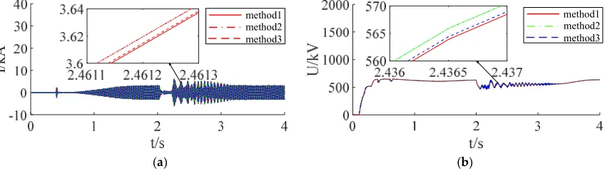
(1) Three phase ground fault in converter bus 3
319
When t = 2s, three phase metal grounding fault of converter bus 3 is set, and the fault is cleared
320
after 0.2s. The simulation result of DC voltage and AC current under single rate and two multi-rate
321
methods is shown in Figure 8.
322
I/
k
A
method1 method2 method3
method1 method2 method3
323
(a) (b)
324
Figure 8. Three phase ground fault in converter bus 3. (a) AC current. (b) DC voltage
325
(2) The ground fault in DC line
326
When t = 2s, the ground fault in DC line is set, and the fault is cleared after 0.2s. The simulation
327
result of DC voltage and AC current under single rate and two multi-rate methods is showed in
328
method 1 method 2 method 3
method 1 method 2 method 3
330
(a) (b)
331
Figure 9.The ground fault in DC line. (a) AC current. (b) DC voltage
332
(3) Error of two multi-rate methods
333
The error between the simulation results of the two multi-rate simulation methods and the
334
single-rate simulation results is shown in Figure 10. It can be seen that the error of multi-rate
335
simulation method based on the Norton equivalent is less than 0.8%, and the maximum error of
336
multi-rate real-time simulation method based on the ideal source equivalence is 2%. The simulation
337
results of the two multi rate methods meet the simulation correctness, but multi-rate real-time
338
simulation method based on the Norton equivalence has higher accuracy.
339
0 1 2 3 4
0 0.01 0.02 0.03 0.04
er
ro
r
method 2
0 1 2 3 4
0 0.01 0.02 0.03 0.04
er
ro
r
method 3
340
Figure 10.Error of two multi-rate methods
341
It can be concluded that the accuracy of multi-rate real-time simulation method based on the
342
Norton equivalence is higher than that based on the ideal source equivalence through the above
343
pictures. Multi-rate real-time simulation method based on the ideal source equivalence take the
344
advantage of the characteristic that the inductance current and capacitance voltage in the circuit
345
cannot be suddenly changed. And the whole system is decoupled by the method of substitution
346
theorem. The equivalent source of the other system is predicted when the fast and slow system is
347
calculated, so the accuracy is slightly worse. The conductance of the Norton equivalence circuit is the
348
true value. It is only necessary to predict the current source of the Norton equivalent circuit of the
349
slow system during the calculation of the fast system, so the accuracy is higher than multi-rate
real-350
time simulation method based on the ideal source equivalent.
351
4. Conclusions
352
With the widespread application of MMC-based power electronic equipment in power systems,
353
multi-rate real-time simulation of AC/DC hybrid power system has a broad application prospect in
354
the field of power system simulation. However, the existing multi-rate simulation methods are not
355
perfect and have poor accuracy.
356
This paper proposes a multi rate real-time simulation method based on the Norton equivalent,
357
compared with multi-rate simulation method based on the ideal source equivalent. After the Norton
358
equivalence of the fast subsystem and the slow subsystem, they are obtained simultaneously at the
359
junction nodes. In order to reduce the amount of simulation calculation, the Norton equivalent circuit
360
is obtained by incremental calculation. The data interface between the fast subsystem and the slow
361
subsystem is realized by extrapolation method. For ensuring the real-time performance of the
362
the slow subsystem with a large amount of calculation. Compared with the traditional multi-rate
364
simulation methods, the paper proposed method improves the simulation accuracy without losing
365
the simulation scale, and has important theoretical and practical significance to research on the
real-366
time simulation of the AC/DC hybrid power system.
367
Author Contributions: conceptualization, J.Z.; methodology, J.Z.; software, J.Z.; validation, J.Z; formal analysis,
368
J.Z; investigation, J.Z.; resources, J.Z; data curation, J.Z; writing—original draft preparation, J.Z; writing—review
369
and editing, J.Z., B.Z.; visualization, J.Z.; supervision, B.Z.; project administration, B.Z.; funding acquisition, B.Z.
370
Funding: This research was funded by the National Natural Science Foundation of China, grant number
371
51477114
372
Conflicts of Interest: The authors declare no conflict of interest.
373
References
374
1. Liu, H.B.; Bian, D.; Sun, L.; Yun, Z.J.; Li, Y. Research on Electromechanical-Electromagnetic Transient
375
Hybrid Simulation of AC/DC Hybrid System. Power System Protection and Control. 2019, 47, 39-47.
376
2. Li Y.L.; Zhang X., Li, Y.J.; Chen, Z.J.; Wu, M.Q. Current Situation and Challenges of Simulation Technology
377
for AC/DC Hybrid Power Grid. Electric Power Construction. 2015, 36, 1-8.
378
3. He, Y.Y.; Zheng, X.D; Tai, N.L.; Hou, J.X.; Xu, J.; Huang, W.T. Overview of Modeling Methods of
LCC-379
HVDC Converter in AC-DC Hybrid Power Grid. Proceedings of the CSEE. 2019, 39,3119-3128.
380
4. Dong, X.Z.; Tang, Y.; Bu G.Q. Confronting Problem and Challenge of Large Scale AC-DC Hybrid Power
381
Grid Operation. Proceedings of the CSEE. 2019, 39, 3107-3119.
382
5. Zhang, M.X. Research on real time multi rate joint simulation technology for power electronic system.
383
Master's Degree, Beijing Institute of Technology, Beijing, 2016.
384
6. Jost, A.; Niklaus, F.; Min, L. High Fidelity Real-Time Simulation of Multi-Level Converters. 2018
385
International Power Electronics Conference, Niigata, Japan, May 20-24, 2018, 2199-2203.
386
7. Zhao, J.L.; Liu, J.T.; Li, P. GPU Based Parallel Matrix Exponential Algorithm for Large Scale Power System
387
Electromagnetic Transient Simulation. 2016 IEEE Innovative Smart Grid Technologies-Asia, Melbourne,
388
Australia November 28- December 1, 110-114.
389
8. Lu, F.S.; Song, J.Q.; Yin, F.K.; Zhang, L.L. Overview of CPU/GPU collaborative parallel computing research.
390
Computer Science. 2011, 38, 5-9.
391
9. Han, J.; Dong, Y.F.; Miao, S.H.; Liu, Y.L; Liu, Z.W. MATE-based multi-rate electromagnetic transient
392
parallel simulation method for power system sub-network. High Voltage Engineering. 2019, 45, 1857-1865.
393
10. CROW, M.L.; CHEN, J.G. The method for simulation of power system dynamics. IEEE Trans on Power
394
Systems. 1994, 9, 1684-1890.
395
11. CHEN, J.G.; CROW, M.L. A variable partitioning strategy for the multi-rate method in power system. IEEE
396
Trans on Power Systems. 2008, 23, 259-266.
397
12. Tang, Y. New Development of Research on Simulation and Modeling of Multi-time Scale Whole Process of
398
AC/DC Power System. Power System Technology. 2009, 33, 1-8.
399
13. Moreira, F.A.; Marti, J.R. Latency techniques for time-domain power system transients simulation. IEEE
400
Transactions on Power Systems. 2005, 20, 246-253.
401
14. Mu, Q; Liang, J.; Zhou, X.X.; Li, G.; Zhang, X. A Node Splitting Interface Algorithm for Multi-rate Parallel
402
Simulation of DC Grids. CSEE Journal of Power and Energy Systems. 2018, 4, 388-397.
403
15. Wang, X.; Zhang, B.D.; Chen, M. Multi-rate time Simulation Method Based on RTDS and FPGA
Co-404
simulation Platform. Automation of Electric Power Systems, 2016, 40, 144-150.
405
16. Zhai, X.B.; Lin, C.; Gregoire, L.A. Multi-rate Real-time Simulation of Modular Multilevel Converter for
406
HVDC Grids Application. IECON 2017 - 43rd Annual Conference of the IEEE Industrial Electronics
407
Society,, Beijing, China, October, 29-November, 1, 2017, 1325-1330.
408
17. Ou, K.J.; Li, P.F.; Guan, L.; Chai, Z.X.; Zhang, Y.J. Design and Research of Multi-time Scale Hybrid
Real-409
Time Simulation System for AC and DC Power Grid. Southern Power System Technology. 2017, 11, 53-58+64.
410
18. Zhang, F.; Huang, W.C.; Li, C.D. MMC generalized fast simulation model suitable for multiple sub-module
411
topologies. Electric Power Automation Equipment. 2019, 39, 129-136+143.
412
19. Jost, A.; Niklaus,` F. Sub-Cycle Average Models with Integrated Diodes for Real-Time Simulation of Power
413
Converters. 2017 IEEE Southern Power Electronics Conference, Puerto Varas, Chile, December 4-7, 2017,