Ankit Raj , Barnali Das , Bikash K. Behera and Prasanta K. Panigrahi 1 Department of Physical Sciences,
Indian Institute of Science Education and Research Kolkata, Mohanpur 741246, West Bengal, India; [email protected]; [email protected]; [email protected]; [email protected] * Correspondence: [email protected]; Tel.: +91-974-891-8201
‡ These authors contributed equally to this work.
Abstract:According to Copenhagen interpretation, a quantum particle can exist in a superposition of all possible states, out of which only one state is observed when it is measured. Interestingly, it has been observed that interaction with the quantum particle during measurement can also affect the outcome of the state. A scheme for interaction free measurement was proposed by Elitzur and Vaidman [Found. Phys. 23, 987 (1993)], where they used Mach Zehnder interferometer to detect whether a bomb is alive or dead. In 25 % of the cases they were able to detect that the bomb is alive without exploding it. Here, we demonstrate the above experiment using quantum computing, which can be realized in a quantum computer designing quantum circuits on it. We explicate all the cases, including whether the bomb is alive or dead by proposing new quantum circuits and executing those in QISKit as provided by IBM Quantum Experience platform and verify the obtained results.
Keywords: Bomb Detection; Interaction Free Measurement; Mach Zhender Interferometer; IBM Quantum Expeience
1. Introduction
The meaning of the word “interaction-free" is that there is no interaction with an object. In case of a bomb, it is quite obvious that explosion means interaction and no interaction means no explosion. Classical physics unequivocally supports this argument but quantum mechanics has its own beautiful way of disproving this. This paves the way to the Interaction Free Measurement (IFM) which has several experimental realizations [1–10] like in novel quantum non-demolition techniques [4,11] for improving cryptographic schemes [12,13] and even for “interaction-free" computation [14]. After Elitzur and Vaidman (EV) IFM proposal [15] further progress in this field leads to higher efficiency [16] Interaction free measurement. In Kwait et al. experiment [1], they used quantum Zeno effect to achieve almost 100 % efficient scheme. Another modification of EV IFM which leads to the efficiency of almost 100 % that has been proposed by Paul and Pavicic [17] and implemented in a laboratory by Tsegaye et al. [4]. The basic concept in their experiment involves optical resonance cavity which is almost transparent when empty and is almost perfect mirror when there is an object inside. Other modifications of IFM are related to interaction free imaging [7] and interaction free measurement of semi-transparent objects. All these experiments achieve an important practical goal of interaction free measurement.
The IBM Quantum Experience (IBM QE) [18] is an online platform that gives users free access to 5-qubit and 14-qubit quantum computers. It allows us to use its python-based software developer kit to write and run quantum algorithms. It has been used in numerous quantum problems for fast calculations and the ability to handle huge data. Unlike the conventional memory units, where each qubit (the smallest unit of information) is represented by a microscopic dot on a microchip in a
quantum information theory [35–37], quantum algorithms [38,39], quantum optimization problems [40], quantum games [41–43], designing quantum communication devices [44,45].
Here, we experimentally realize the above experiment using the IBM QE platform. We propose new quantum circuits and design those using QISKit to demonstrate the scheme of Elitzur and Vaidman Interaction Free Measurement. We exploit the use and application of a quantum computer which can be utilized to illustrate experiments that have been performed using other architectures such as Michelson Interferometer or other optical setups. Similar works have already been done [34,44] where a quantum computer has been used to show its future application even if no experimental architectures are easily available to a researcher.
The rest of the paper is organized as follows. Section2briefly describes the scheme of Elitzur and Vaidman Interaction Free Measurement (EV IFM). Section3discusses about the operations used in the quantum circuit for the proposed experiment. In Section4, we elaborate the quantum circuits for Elitzur and viadman model for IFM. Sections5and6introduce the cases when the bomb is live and dead respectively. Finally, we conclude in Section7and discuss about the future direction of the present work.
2. Scheme of Elitzur and Vaidman Interaction Free Measurement (EV IFM)
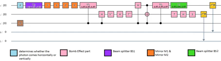
Figure 1.Quantum circuit illustrating the scheme for the bomb detection in the quantum computer. The different coloured parts represent different components of the experimental setup in terms of various gates. The absence of sky blue coloured box implies that the photon is directed from vertical direction while its presence implies that it is directed from horizontal direction. Pink coloured part represents bomb effect part, Violet coloured box represents beam splitter 1 (BS1), green box represents beam splitter 2 (BS2) and Yellow boxes are measurement boxes. The presence of brown box tells that the bomb is present.
3. Quantum Gates used in the experiment
The beam splitter BS1 and beam splitter BS2 in the Figs.3,6,9, and12are defined by U3 operation. The mirrors M1 and M2 in the Figs.3,6,9, and12are composed of sequential operation of X, Y, Z and X gates. The operations for the effect of bomb part are U3, H,S†,T†,U3†, S and T, whose matrix forms are explicitly given below.
X =
" 0 1 1 0
# ,Y =
" 0 −i i 0
# , Z =
"
1 0
0 −1 #
,U3 = √1 2
" 1 i
i 1 #
, H = √1 2
"
1 1
1 −1 #
,
S†= "
1 0
0 −i #
,T†= "
1 0
0 1√−i 2
#
,U3†= √1 2
"
1 −i −i 1
# ,S=
" 1 0 0 i
# ,T=
"
1 0
0 1√+i 2
# .
4. Quantum circuit for interaction free measurement
Figure 3. Quantum circuit for the case when the bomb is not alive and the input is from vertical direction. As it can be seen, there is no X gate on the qubitq0, hence the state of the qubitsq0andq1 is in|00istate, that implies the vertical direction of the photon. The qubitan0is in|0istate, which signifies there is no bomb in the path or the bomb is dead. Hence the part of bomb effect, i.e., the controlled operations from the qubitan0to the first two qubitsq0andq1would have no effect.
5. CASE-1: No bomb or dead bomb
When the input of photon is from vertical direction
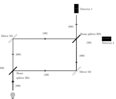
Figure 2.Setup when the bomb is not alive and the photon input is from vertical direction. In this case D1 will click and D2 will not. Constructive interference will occur at D1 while destructive interference at D2.
Here if no bomb is there then the states of the photon superpose with each other constructively and destructively at respective detectors (depending on the direction of input of the photon). And if the bomb is dead then also superposition occurs because it (the photon-sensitive bomb) allows the photon to pass through it without any disturbance. The input photon is from vertical direction (by convention discussed in scheme in the Section4), which is taken to be|00istate as shown in Fig.2. Initially, as there is no bomb, the state of the whole system is given as|000i. On passing the photon through BS1 i.e. applying the U3 gate on the first qubitq0we get(|0i√+2i|1i)|00i. As it passes through M1, M2 and bomb effect part we get(−|0√i+i|1i)
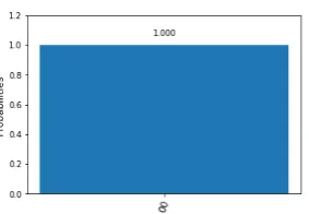
Figure 4.Histogram for the case when the input is from vertical direction and only D1 clicks, i.e., the probability of|00iis 1.
When direction of input photon is horizontal
The input of photon is from horizontal direction (by convention), which is taken to be|10ias shown in Fig.5. As the photon is in the horizontal direction and the bomb is dead, the state of the whole system is given as|100i. On passing the photon through BS1 i.e. applying the U3 gate on the first qubitq0 we get, (|1i√+2i|0i)|00i. As it passes through M1, M2 and bomb effect part we get,
(−|1√i+i|0i)
2 |00i. On passing the photon through BS2 i.e. applying the U3 gate on the first qubitq0we get, -|100i. The final state of the photon is calculated to be|10i, which implies the photon will be detected at the detector D2. The histogram showing the probability of|10iis illustrated in the Fig.7, that confirms the expected result. The detailed calculation of the quantum circuit shown in Fig.6can be found in Appendix SectionA.1.2. The optical setup depicting the above scenario is presented in the Fig.5.
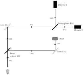
Figure 5.Setup for the cases when the bomb is not alive and the input is from horizontal direction. In this case D2 will click and D1 will not click. Constructive interference will occur at D2 while destructive interference at D1.
6. CASE-2: When the bomb is there
When the input photon is from vertical direction
The input of photon is from vertical direction (by convention), which is taken to be|00istate as shown in Fig. 8. As the bomb is there and the photon is from vertical direction, the state of the whole system is |001i. On passing the photon through BS1 i.e. applying the U3 gate on the first qubitq0we get, (|0i√+2i|1i)|01i. On applying the mirrors M1, M2 and bomb effect part we get, −(1−i
√
2)|001i+(i−√2)|101i+|011i−i|111i
2√2 . The resultant state on applying BS2 is−
|00i+|01i
2 −
|√10i
Figure 6.Quantum circuit for the cases when the bomb is not alive and the input is from horizontal direction. X gate is applied on the qubitq0to denote the horizontal direction of the photon and the qubitan0in state|0irepresents the absence of the bomb.
Figure 7.Histogram for the cases when the input is from horizontal direction, bomb is not alive then D2 clicks.
Figure 9. Setup for the cases when the bomb is alive and the input is from vertical direction. If the photon chooses lower path then explosion will occur (50 % of the cases) and when it chooses the upper path either of the detector (D1 or D2) clicks with 25-25 % probability.
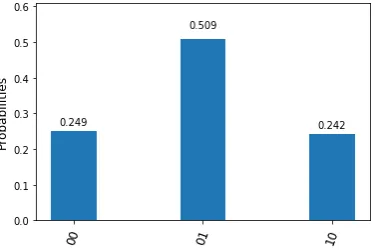
Figure 10. Histogram for the case when the bomb is alive and the input photon is from horizontal direction. The outcome’s digit should be read from upper to lower i.e., the first, second and third bars of histogram represent the outcomes as|00i,|10i,|01irespectively.
observed that the photon with 0.5 probability, is not detected anywhere, which is denoted by the state |10istate.
When input photon is from horizontal direction
Figure 12. Setup for the case when the bomb is alive and input is from horizontal direction. If the photon chooses lower path then explosion will occur (50 % of the cases) and when it chooses the upper path either of the detector (D1 or D2) clicks with 25-25 % probability.
The input of photon (from horizontal direction) is taken to be|10istate as shown in Fig.11and due to the presence of bomb, the state of the whole system is|101i. On passing the photon through BS1 i.e., applying the U3 gate on the first qubitq0we get(|1i√+2i|0i)|01i. On applying the mirrors M1, M2 and bomb effect part we get,−(1+i
√
2)|001i+(i+√2)|101i+|011i−i|111i
2√2 . The resultant state after applying BS2 is−|00i+2|01i+|√10i
Figure 11.Quantum circuit illustrating the case when the bomb is alive and the input is from horizontal direction. X gates are applied on the qubitsq0andan0to represent the horizntal direction of the photon and the presence of bomb respectively.
it. The term “IFM" needs to be clarified here, as we cannot say in all the cases whether the bomb is alive or dead with certainty because there is 50 % probability that the bomb will explode (i.e., the observer is interacting with the system) when it is alive. Also out of the rest 50 % cases, in 25 % of the cases we do not know if the bomb is live or dead. In the near future, the present work can be extended to demonstrate the Kwait et al. experiment [1] using quantum computation which can achieve IFM with almost 100 % efficiency.
Author Contributions: Data Collection and Analysis, A.R. and B.D.; Scheme Analysis, A.R., B.D. and B.K.B.; Circuit Design, A.R., B.D. and B.K.B.; Investigation, A.R., B.D. and B.K.B.; Methodology, A.R. and B.D.; Project Administration, B.K.B.; Resources, A.R. and B.D.; Computations, A.R. and B.D.; Validation, A.R, B.D. and B.K.B.; Visualization, A.R., B.D. and B.K.B; Supervision, B.K.B. and P.K.P.; Writing-Original draft, A.R. and B.D.; Writing-Review and Editing, B.K.B. and P.K.P.
Funding:B.K.B. acknowledges the financial support of IISER Kolkata.
Acknowledgments: We acknowledge the hospitality of Indian Institute of Science Education and Research Kolkata during the project work. We thank Yugojyoti Mohanta (IISER Berhampur) for helping us avail QISKit. We acknowledge the support of IBM Quantum Experience for using the quantum processors. The views expressed are those of the authors and do not reflect the official position of IBM or the IBM quantum experience team.
Conflicts of Interest:The authors declare no conflict of interest.
Appendix A. Equations involved in mirrors M1 and M2
Appendix A.1. When the bomb is absent
Appendix A.1.1. Path is vertical
On applying operations of mirrors and bomb effect part one by one we get a. Y gate onq0→ (|0i+√i|12i)|00i
b. X gate onq0→ (|1i+√i|02i)|00i c. Z gate onq0→ (−|1i+√i|20i)|00i d. X gate onq0→ (−|0i+√i|21i)|00i
e. Controlled U3 gate onq0only ifan0is|1i → (−|0i+√i|21i)|00i f. Controlled H gate onq0only ifan0is|1i → (−|0i+√i|21i)|00i g. Controlled H gate onq1only ifan0is|1i → (−|0i+√i|21i)|00i h.S†gate onq
1→ (−|0i+√i|21i)|00i
i. H gate onq1→ (−|0i+i|1i√)(2|0i+|1i)|0i
o. S gate onq1→(|0i+√i|12i)|00i
Appendix A.1.2. when the direction is horizontal
On applying the operations of mirrors and bomb effect part one by one we get
a. Y gate onq0→ (−|1i−√i|20i)|00i b. X gate onq0→ (|0i−√i|12i)|00i c. Z gate onq0→ (−|0i+√i|21i)|00i d. X gate onq0→ (−|1i+√i|20i)|00i
e. Controlled U3 gate onq0only ifan0is|1i → (−|1i+√i|20i)|00i f. Controlled H gate onq0only ifan0is|1i → (−|1i+√i|20i)|00i g. Controlled H gate onq1only ifan0is|1i → (−|1i+√i|20i)|00i h.S†gate onq1→ (−|1i+√i|20i)|00i
i. H gate onq1→ (
−|1i+i|0i√)(|0i+|1i)|0i 2
j.T†gate onq1→ (i|00i+(i+1)(|01i−|2√102 i−(1−i)|11i)|0i
k. Controlled not Controlled gate onq1only ifan0&q0 are|1i → (i|00i+ (i+√1)2|01i− |10i − (1−√i)|11i
2 ) |0i
2
m. T gate onq1→ (
−|1i+i|0i)(|0i+|1i)|0i 2
n. H gate onq1→ (−|1i+√i|20i)|00i o. S gate onq1→(
a. Y gate onq0 2 b. X gate onq0→ (|1i+√i|02i)|01i c. Z gate onq0→ (−|1i+√i|20i)|01i d. X gate onq0→ (−|0i+√i|21i)|01i
e. Controlled U3 gate onq0only ifan0is|1i → −|001i f. Controlled H gate onq0only ifan0is|1i → (|0i+√|12i)|01i
g. Controlled H gate onq1only ifan0is|1i → −(|0i+|1i)(|20i+|1i)|1i h. S+ gate onq1→ −(|001i−i|011i+2|101i−i|111i)
i. H gate onq1→ −(1−i)|001i+(1+i)|0112i√+(21−i)|101i+(1+i)|111i j. T+ gate onq1→ −(1−i)|001i+
√
2|011i+(1−i)|101i+√2|111i 2√2
k. Controlled not Controlled gate on q1 only if an0 & q0 are |1i → −(1−i)|001i+
√
2|011i+(1−i)|111i+√2|101i 2√2
l. T gate onq1→ −(1−i)|001i+(1+i)|011i+ √
2|101i+√2|111i
2√2 )
m. H gate onq1→ −|0012i+i|0112 i−|101√2i n. S gate onq1→ −|0012 i+
|011i 2 −
|101√ i 2
Appendix A.2.2. Path is horizontal
On applying the operations of mirrors and bomb effect part one by one we get
a. Y gate onq0→ (−|1i−√i|20i)|01i b. X gate onq0→ (−|0i−√i|21i)|01i c. Z gate onq0→ (−|0i+√i|21i)|01i d. X gate onq0→ (−|1i+√i|20i)|01i
j. T+ gate onq1→ − 2 2
k. Controlled not Controlled gate on q1 only if an0 & q0 are |1i → −(1−i)|001i+|011i−(1−i)|111i−
√ 2|101i 2√2
l. T gate onq1→ −(1−i)|001i+(1+i)|011i− √
2|101i−√2|111i 2√2
m. H gate onq1→ −|0012 i+
i|011i
2 +
|101√i 2
n. S gate onq1→ −|0012 i+|0112i+|101√2i
References
1. Kwiat, P.; Interaction-Free MeasurementPhys. Rev. Lett.1995,74, 4763.
2. Voorthuysen, E. H.; Realization of an interaction-free measurement of the presence of an object in a light beam.Am. J. Phys.,1996,64, 1504.
3. Hafner, M.; Summhammer, J.; Experiment on interaction-free measurement in neutron interferometry.Phys. Lett. A.1997,235, 563
4. Tsegaye,T.; Goobar,E.; , Karlsson A.; Bjork ,G.; Loh, M. Y.; Lim, K. H.; Efficient interaction-free measurements in a high-finesse interferometer.Phys. Lett. A.1998,57, 3987.
5. White, A. G.; Mitchell, J. R., Nairz, O.; Kwiat, P.; “Interaction-free” imaging.Phys. Lett. A.1998,58, 605. 6. Kwiat, P.;Phys. Scripta1998,76, 115.
7. White, A. G.; Mitchell, J. R., Nairz, O.; Weihs, G.; Weinfurter,H.; and Zeilinger, A.; Kwiat, P.High-Efficiency Quantum Interrogation Measurements via the Quantum Zeno Effect.Phys. Rev. Lett.1999,83, 4725. 8. Mirell, S.; Mirell, D.; arXiv:quant-ph/0509028
9. Rudolph,T.; Better Schemes for Quantum Interrogation in Lossy Experiments.Phys. Rev. Lett.2000,85, 2925. 10. Elitzur, A. C.; Dolev, S.;Nonlocal effects of partial measurements and quantum erasure.Phys. Rev. A2001,63,
062109.
11. Potting, S.; Lee, E. S.; Schmitt, W.; Rumyantsev, I.; Mohring, B.; Meystre, P.; Quantum coherence and interaction-free measurements.Phys. Rev. A2000,62060101(R).
12. Guo, G. C.; Guo Shi, B. S.; Quantum cryptography based on interaction-free measurement.Phys. Lett. A. 1999,256109.
13. Czachor, M.; Quantum cryptography with polarizing interferometers.Phys. Lett. A.1999,257, 107.
14. Mitchison, G.;Jozsa, R.; Counterfactual computation.Proc. Royal Soc. A: Math. Phys. Eng. Sci.2001,457, 1175. 15. Elitzur, A. C.; Quantum mechanical interaction-free measurements.Found. Phys.1993,23, 987.
16. Vaidman, L.; The Meaning of the Interaction-Free Measurements.Found. Phys.2003,33, 491.
17. Pavicic, M.; Resonance energy-exchange-free detection and “welcher Weg” experiment.Phys. Rev. A1996, 223, 241.
18. IBM Quantum Experience,URL: https://quantumexperience.ng.bluemix.net/qx/community. 19. QISKit,URL: https://github.com/Qiskit/qiskit-terra.
20. Jupyter Notebook,URL: https://jupyter.org/.
dynamics using quantum computer.Quantum Inf. Process.2018,17, 223.
26. Hegade, N. N.; Behera, B. K.; and Panigrahi, P. K. Experimental Demonstration of Quantum Tunneling in IBM Quantum Computer. arXiv:1712.07326.
27. Halder, K.; Hegade, N. N.; Behera, B. K.; Panigrahi, P. K. Digital Quantum Simulation of Laser-Pulse Induced Tunneling Mechanism in Chemical Isomerization Reaction. arXiv:1808.00021.
28. Malik, G. R.; Singh, R. P.; Behera, B. K.; Panigrahi, P. K. First Experimental Demonstration of Multi-particle Quan-tum Tunneling in IBM Quantum Computer. DOI: 10.13140/RG.2.2.27260.18569.
29. Vuillot, C. Is error detection helpful on IBM 5Q chips?.Quantum Inf. Comput.2018,18, 0949
30. Ghosh, D.; Agarwal, P.; Pandey, P.; Behera, B. K.; and Panigrahi, P. K. Automated error correction in IBM quantum computer and explicit generalization.Quantum Inf. Process.2018,17, 153.
31. Singh, R. K.; Panda, B.; Behera, B. K.; and Panigrahi, P. K. Demonstration of a general fault-tolerant quantum error detection code for (2n+1)-qubit entangled state on IBM 16-qubit quantum computer. arXiv:1807.02883. 32. Satyajit, S.; Srinivasan, K.; Behera, B. K.; and Panigrahi, P. K. Nondestructive discrimination of a new family
of highly entangled states in IBM quantum computer.Quantum Inf. Process.2018,17, 212.
33. Behera, B. K.; Banerjee, A.; Panigrahi, P. K. Experimental realization of quantum cheque using a five-qubit quantum computer.Quantum Inf. Process.2017,16, 312.
34. Biswas, S.; Razdan, S.; Behera, B. K.; and Panigrahi, P. K. Realization of Counterfactual Quantum Cryptography Us-ing IBM’s Quantum Computer. DOI: 10.13140/RG.2.2.30090.52160.
35. Alsina, D.; Latorre, J. I. Experimental test of Mermin inequalities on a five-qubit quantum computer.Phys. Rev. A2016,94, 012314.
36. Kalra, A. R.; Gupta, N.; Behera, B. K.; Prakash, S.; Panigrahi, P. K. Demonstration of the No-Hiding Theorem on the 5 Qubit IBM Quantum Computer in a Category Theoretic Framework. arXiv:1707.09462.
37. Swain, M.; Rai, A.; Behera, B. K.; and Panigrahi, P. K. Experimental demonstration of the violations of Mermin’s and Svetlichny’s inequalities for W- and GHZ-class of states. arXiv:1810.00874.
38. Singh, R. P.; Behera, B. K.; and Panigrahi, P. K. Quantum algorithm for sum of infinite series; determining the value ofπ. DOI: 10.13140/RG.2.2.21343.10408.
39. Gangopadhyay, S.; Manabputra; Behera, B. K.; and Panigrahi, P. K. Generalization and demonstration of an entanglement-based Deutsch–Jozsa-like algorithm using a 5-qubit quantum computer.Quantum Inf. Process. 2018,17, 160
40. Srinivasan, K.; Satyajit, S.; Behera, B. K.; and Panigrahi, P. K. Efficient quantum algorithm for solving travelling salesman problem: An IBM quantum experience. arXiv:1805.10928.
41. Pal, A.; Chandra, S.; Mongia, V.; B. K. Behera and Panigrahi, P. K. Solving Sudoku Game Using Quantum Computation. DOI: 10.13140/RG.2.2.19777.86885.
42. Roy, B. B.; Behera, B. K.; and Panigrahi, P. K. Modelling A Simple Shooting Game Using Quantum Computation. DOI: 10.13140/RG.2.2.30976.07680.
43. Paul, S.; Behera, B. K.; Panigrahi, P. K. Playing Quantum Monty Hall Game in a Quantum Computer. arXiv:1901.01136.
44. Behera, B. K.; Reza, T.; Gupta, A.; Panigrahi, P. K. Designing Quantum Router in IBM Quantum Computer. arXiv:1803.06530. 2018
45. Behera, B. K.; Seth, S.; Das, A.; Panigrahi, P. K.;arXiv:1712.00854.