Division II, Paper ID 181
WORKSHOP:
INTEGRITY ASSESSMENT POSITION PAPERS IN THE FRAMEWORK
OF THE NUGENIA ASSOCIATION
POSITION PAPER: FRACTURE MECHANICS ASSESSMENT
John Sharples1, Elisabeth Keim2, Dana Lauerova3
1
Business Manager and Structural Integrity Consultant, AMEC Foster Wheeler, UK
2
Head of Department Fracture Mechanics, Materials Testing and Irradiation Behaviour, AREVA GmbH, Germany
3
Senior Research Scientist, UJV Rez, a.s., Czech Republic
ABSTRACT
Fracture mechanics is associated with describing the behaviour of crack-like defects in engineering systems, structures and components by way of defining the conditions (e.g. stresses and strains) local to the crack tip. In an engineering sense, such conditions are usually defined by the elastic stress intensity factor parameter (KI) or the elastic-plastic J-integral parameter (J). These structural parameters are considered in conjunction with relevant fracture mechanics material properties in order to assess the behaviour and significance of the defect.
A recently completed EC Framework STYLE project was focussed on various structural features found in piping and associated components. These features were primarily those of a dissimilar metal weld, a repaired weld and a ferritic pipe with internal austenitic stainless steel cladding. A NUGENIA position paper has been produced that is largely focussed on the main findings of the STYLE project in relation to fracture mechanics assessment methodology employed in the various European countries. In addition to the information resulting from the STYLE project, other aspects of fracture mechanics assessment have been included in the position paper.
This paper summarises the main information contained in the NUGENIA position paper and firstly deals with general aspects of fracture mechanics assessment in terms of the current understanding and where further work is required. This is in relation to a general sense and specifically to fracture and to fatigue crack growth. Specific aspects relating to RPVs are then covered followed by specific aspects relating to piping and associated components as highlighted from the STYLE project.
INTRODUCTION
A NUGENIA position paper has been produced (Sharples et. al. 2015) covering various aspects of fracture mechanics assessment. A recently completed EC Framework STYLE project (Nicak and Keim 2010) was focussed on various structural features found in piping and associated components. These features were primarily those of a dissimilar metal weld, a repaired weld and a ferritic pipe with internal austenitic stainless steel cladding. Whilst covering the various aspects, the NUGENIA position paper is heavily focussed on the main findings of the STYLE project in relation to fracture mechanics assessment methodology employed in the various European countries.
(RPVs) are then covered followed by specific aspects relating to piping and associated components as highlighted from the STYLE project.
GENERAL ASPECTS
General
There are various aspects relating to fracture mechanics which are common to both fracture and fatigue crack growth assessments. Such main aspects considered in the position paper are associated with defect characterisation, stress intensity factor solutions, mixed mode loading, treatment of weld residual stresses and characterisation of loads. Details relating to the treatment of weld residual stresses are considered here.
Stresses resulting from welding processes are of a varying type and are self balancing throughout the structure or component. Consequently, they are categorised as secondary stresses. In welds with no post weld heat treatment (PWHT), such stresses can attain magnitudes approaching or exceeding the yield value (e.g. 0.2% proof stress) of the material, and they should be considered when assessing crack-like defects located in the tensile region (based on un-cracked body analysis). This is particularly true for situations where the applied primary stresses do not result in significant plasticity in the section containing the crack. For situations where there is significant yielding in the “cracked section”, the influence of the weld residual stresses will be substantially reduced due to plasticity effects and hence become of less importance. Unified European guidance on the treatment of weld residual stresses could usefully be formulated. This should include such aspects as PWHT, mechanical treatments and load history and temperature effects.
Fracture
Fracture assessments are often required to evaluate the critical, or limiting, defect size in a structural component. Aspects specifically relating to fracture considered in the position paper are associated with plastic collapse solutions, allowance for ductile tearing, benefits of crack-tip constraint considerations, treatment of combined primary and secondary stresses and the treatment of non crack-like defects. Details relating to crack-tip constraint are considered here.
The enhanced understanding of crack-tip constraint effects and the potential to be able to realise its benefit in structural integrity assessments is probably the most significant development in the field of fracture mechanics in recent years. This arises from the fact that a particular conservatism inherent in conventional fracture mechanics assessments is that the value of fracture toughness used is normally derived from deeply cracked standard specimens using recommended testing standards and validity criteria. These are designed to ensure conservative conditions with high hydrostatic stresses (i.e. high stress triaxiality) near the crack tip. However, it is known that the material resistance to fracture in the brittle to transition regime is increased when, for instance, specimens with shallow cracks are tested. These conditions lead to lower hydrostatic stresses (i.e. low stress triaxiality) at the crack tip, referred to as lower constraint.
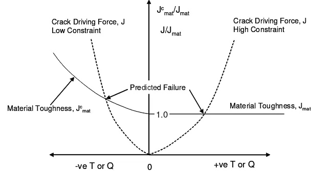
Figure 1: Fracture toughness and crack driving force in J-Q space
The philosophy behind the application of crack-tip constraint methodology in the brittle to ductile regime can perhaps best be understood in diagrammatic form by plotting fracture toughness J against the T or Q parameter (Figure 1 – where J modified for crack-tip constraint, JCmat is shown normalised by the
conventional plane strain fracture toughness, Jmat). This diagram defines the “failure” curve. There is
generally an upswing in the toughness as Q (and T) becomes more negative, the more negative the Q (or T), the lower the crack-tip constraint. Values of fracture toughness corresponding to Q (or T) equal to zero or positive values represent the high crack-tip constraint regime which is relevant to conventional toughness, as evaluated from deeply cracked standard specimens. Structural J loci can be constructed on the diagram so that the “failure” point can be evaluated, as that point being where the “failure” curve is attained. Certainly for primary loads, cracks to be assessed in structural components are often of low crack-tip constraint (i.e. negative Q or T) and hence the “structural” fracture toughness is likely to be greater than the conventional fracture toughness. When there is a combination of primary and secondary stresses, there could be a tendency for the crack-tip constraint in structural components to be higher (i.e. less negative Q or T) than for primary stresses acting alone. One of the reasons for this is the fact that secondary stresses are predominantly more bending than membrane in nature.
The consideration of crack-tip constraint therefore provides a powerful tool for assessing structural components by way of using the “real” fracture toughness of the component as opposed to the “lower bound” conventionally used. One area requiring further development leading to unified guidance is a test procedure for evaluating fracture toughness under low crack-tip constraint conditions (e.g. shallow cracked bend specimens), including in the ductile regime. In fact, unified detailed guidance could usefully be developed on constraint based methodology in general, particularly in order to ensure that the “failure” curve, as described above, is constructed so as to be unique for a given material and temperature irrespective of whether the loading in the structural component is of primary stress, secondary stress or a combination of the two, the latter being the case in the vast majority of practical situations.
Fatigue Crack Growth
Based on knowledge of the operational cycles of the component being assessed, a fatigue crack growth calculation can be undertaken to evaluate how large an “initial” defect is likely to grow over a given operational period. This is an important aspect in flaw tolerance assessments. It is then required to demonstrate that the “grown” defect is of a size, significantly smaller (mainly by applying a specific safety factor) than that of the critical or limiting defect. Aspects specifically relating to fatigue crack growth considered in the position paper are associated with counting, combining and applying transient
0
-ve T or Q +ve T or Q
Jc mat/Jmat
1.0
J/Jmat
Predicted Failure
Material Toughness, Jc mat
Crack Driving Force, J High Constraint Crack Driving Force, J
Low Constraint
Material Toughness, Jmat
0
-ve T or Q +ve T or Q
Jc mat/Jmat
1.0
J/Jmat
Predicted Failure
Material Toughness, Jc mat
Crack Driving Force, J High Constraint Crack Driving Force, J
Low Constraint
cycles, allowing for crack closure effects and low and high ∆K regimes. Details relating to the last of
these aspects are considered here.
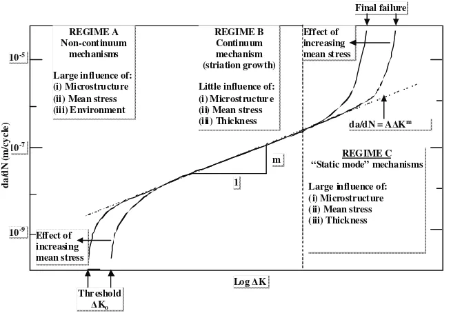
The so-called Paris Law relationship is usually applied to calculate the cyclic fatigue crack growth. It is
the linear mid-region of the da/dN (crack growth per cycle) versus ∆K relationship when plotted on a
log-log scale (Figure 2). There are two other regions though which sometimes need to be considered when undertaking fatigue crack growth calculations. One of these is the threshold region which represents
crack growth rates typically below 10-8m/cycle. On account of the very low propagation rates possible at
low ∆K, total crack propagation life is often dominated by the proportion of life spent in this regime.
Where the applied ∆K is less than the threshold value, crack growth rates are effectively zero. Threshold
∆K data for a wide variety of mild and low alloy steels have been collated in the literature. The other
regime is that describing fatigue crack growth near final failure. For ductile materials, this region is associated with when the elastic-plastic driving force (represented by J for example) corresponding to the maximum applied stress in the cycle approaches the initiation fracture toughness. For situations where the driving force exceeds the initiation fracture toughness, then crack growth by the mechanism of combined fatigue and tearing needs to be considered. Based on the results of experimental data, the R6 procedure (EDF Energy 2015) for example proposes that this may satisfactorily be achieved by a model involving linear summation of tearing and fatigue crack growth.
It is worth mentioning that a number of crack growth laws have been proposed in the literature to describe
the entire da/dN versus ∆K relationship, from the threshold region through to the “Paris Law” region and
through to the near final failure region. One of these is the so-called NASGRO equation (NASA 2002). Any European-wide guidance on fatigue crack growth, could therefore usefully include consideration of the threshold and near final failure regions.
Figure 2: Sigmoidal variation of fatigue crack growth rate (da/dN) with stress intensity factor range
(∆K) and associated fracture mechanisms
REGIME A Non-continuum
mechanisms
Large influence of: (i) Microstructure (ii) Mean stress (iii) Environment
REGIME B Continuum mechanism (striation growth)
Little influence of: (i) Microstructure (ii) Mean stress (iii) Thickness
REGIME C “Static mode” mechanisms
Large influence of: (i) Microstructure (ii) Mean stress (iii) Thickness
Final failure
Effect of increasing mean stress
da/dN = AǻKm
ASPECTS RELATING TO RPVs
The reactor cores of the majority of the worlds’ nuclear power reactors are housed in steel reactor pressure vessels (RPVs), whose primary function is to contain both the reactor core and the primary coolant under operational conditions of temperature and pressure. The integrity of the thick walled steel RPV is vital for safety. Therefore it is necessary to demonstrate that disruptive failure of the RPV is practically excluded and has a very low probability of occurrence, bordering on the incredible, throughout its working life, since such accidents could give rise to large uncontrolled releases of radioactivity to the public. In considering long life operation of RPVs, one of the main aspects required to be carefully taken into account is the extent to which neutron irradiation causes a shift in the ductile to brittle transition temperature resulting in the material becoming more brittle. Fracture mechanics assessment therefore inevitably plays a very important role in assuring the safety of RPVs (Keim et. al. 2008).
Aspects specifically relating to RPVs considered in the position paper are associated with pressurised thermal shock (PTS) analysis, warm pre-stressing (WPS), long term irradiation effects and the treatment of cladding. Details relating to the last of these aspects are considered here.
Austenitic stainless steel cladding, up to a few millimetres in thickness, is applied by the weld deposition of one, or more, layers (usually two) to the inside wall of Light Water Reactor RPVs. This is to inhibit general corrosive attack of the ferritic low-alloy steel base material, and to minimise any associated radioactive contamination of the reactor coolant system. A full understanding of the behaviour of clad regions under PTS conditions is essential to the development of improved methods of RPV assessment. The need for this understanding is particularly important in relation to crack front behaviour in the clad/heat affected zone (HAZ)/base metal interface region. There is currently no clear consensus in Codes and Standards for assessing the influence of austenitic cladding in RPV assessments. Whilst for example the German KTA Code (Safety Standards KTS 3201 2013) provides some guidance on how to treat the cladding in a PTS event, other Codes give practically no guidance.
Residual stresses in the cladding can be taken into account by the definition of the stress free temperature. Depending on the temperature of the vessel relative to the so-called “stress free” temperature, tensile residual stresses can exist in the cladding, with a steep gradient to much lower, possibly compressive, stresses in the base metal.
Because of this gradient effect, cladding residual stresses are likely to have only a relatively small effect on the driving force for fracture at positions on a crack front below the clad-base metal interface. During a PTS transient, the cladding is subject to significant plastic deformation, which serves to reduce the cladding stresses to a low level after the transient. Warm pre-stressing, linked with the presence of cladding, is a factor that will tend to inhibit crack initiation in cleavage during PTS transients. WPS benefits refer here to the so-called “conservative” WPS principle. This means that the transients which after the maximum crack driving force show a strong monotonic reducing “load path”, crack initiation is excluded, if the crack tip of a postulated flaw has seen a warm pre-loading in the present transient.
As has been noted above, there is currently no clear consensus in all available Codes and Standards for assessing the influence of austenitic cladding in RPV assessments and this is obviously an area where the development of suitable guidance at the European level would be advantageous.
ASPECTS RELATING TO PIPING AND ASSOCIATED COMPONENTS
General Aspects
referred to above are relevant. In addition, there are various structural features which may require additional consideration. Some such features were addressed under the recent STYLE European project (Nicak and Keim 2010) and this section of the position paper is dedicated to taking on board the information gained from that project in relation to fracture mechanics assessment. Leak-Before-Break (LBB) was highly featured in STYLE since LBB arguments are fairly commonly used nowadays as part of the safety justification for piping systems, mainly as a defence-in-depth element.
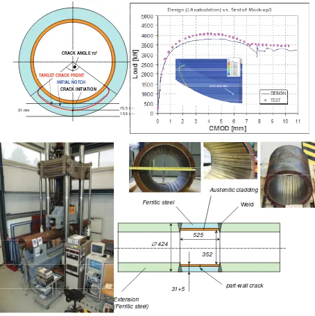
STYLE (Structural integrity for lifetime management – non-RPV components) was a four year project, running from January 2010 to December 2013, consisting of 20 participating European organisations. The project was aimed at establishing enhanced tools and methodology to be applied in lifetime assessments of pipework and associated components. In assessing the structural integrity of welded and clad components, the influence of residual stresses resulting from the weld/fabrication process can be significant and consequently the evaluation of such stresses, by both experimental and analytical techniques, featured strongly in various work packages of the STYLE project. The project was centred on structural mock-up and supporting experiments. The structural mock-up experiments contained pipes loaded under global bending with features of (i) a narrow gap dissimilar metal weld (DMW), (ii) a repair weld in an austenitic steel butt weld, and (iii) an austenitic clad ferritic pipe (Figure 3).
Figure 3: STYLE mock-up 3 experiment (Clad pipe)
Within STYLE, an overview of fracture mechanics methodologies (referred to in the project as Engineering Assessment Methods (EAMs)) applied in different European countries was obtained, including commonalities and differences. This was particularly with respect to application to Dissimilar Metal Welds, Repair Welds and Clad pipes. A similar exercise was undertaken on overviewing LBB methods applied in European countries, including evolution and the regulatory position. Latterly in the project, participating organisations applied their various EAMs to case studies that had been developed based on the three structural mock-up experiments.
15,5 mm 15,5 mm 31 mm
CRACK INITIATION
TARGET CRACK FRONT
CRACK ANGLE 72º
INITIAL NOTCH
part-wall crack Austenitic cladding
Ferritic steel Weld
Extension (Ferritic steel)
∅424
525
Overview of fracture mechanics methodologies applied to piping in general within European countries with particular emphasis on dissimilar metal welds, repair welds and clad pipes
A qualitative comparison of EAMs was undertaken by collating relevant information obtained from the various participants. The main aspects of the study were related to the structural features of the three mock-up Experiments referred to above. The individual partners provided brief descriptions of their EAMs for structural integrity evaluations of dissimilar metal welds, repair welds and clad ferritic pipes. In their contributions, special attention was intended to be focussed on such aspects as mismatch of material properties, residual stresses, mixed-mode loading and constraint effects.
In studying the contributions received from the participating organisations, several types of commonalities and differences were evident. One commonality for example relates to the use of a commonly adopted assessment code or methodology. Nearly all partners reported using the ASME Codes (ASME III, ASME XI) either as their main assessment code or in addition to their national codes. For assessing the three types of structural features considered though, many of the participants reported that they would undertake detailed finite element analyses, as a supplementary or as an alternative to their codes or procedures. One difference identified is associated with the provision of guidance for treating weld residual stresses when assessing flawed component. Whilst, for example, the R6 methodology provides detailed guidance on how to determine the residual stress variation in the weld, some other codes, such as the French, provide practically no guidance.
Overview of leak-before-break methods applied to European countries including evolution and regulatory position
A qualitative overview of leak-before-break (LBB) national practices and the regulatory position for the different participants was undertaken early in the STYLE project. The information relating to the individual countries was generally considered in relation to LBB practice, regulatory position, evolution, application, past and present research activities and future plans.
The study highlighted that the main distinction between different countries is in the actual procedure adopted. However, all methods adopt a similar approach in making the basic case for an LBB argument. The argument simply states that a crack should be large enough so that the loss of fluid escaping the through wall crack can be detected, whilst remaining small enough that structural failure of the pipe does not occur. Clearly there are many assumptions which are used within this assessment which differ by country, some of which are dependent on the national regulatory position. Examples of such variations are the required margins between detectable crack size and critical crack size, leak detection requirements, flaw geometry and assumed flow rates.
Overview of fracture mechanics assessment methods applied to STYLE Mock-up experiments
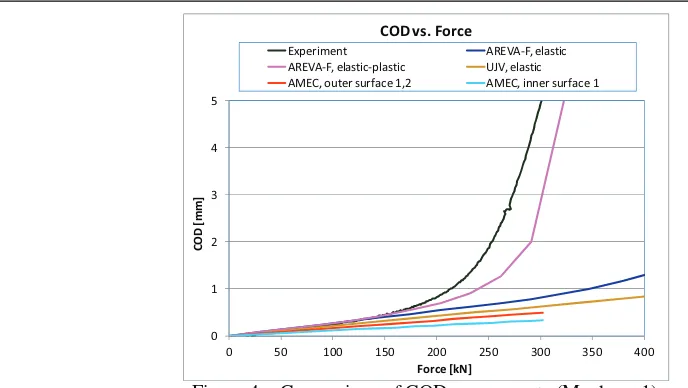
Figure 4: Comparison of COD assessments (Mock-up 1)
Benchmarks, based on each of these experiments were launched to investigate fracture assessment procedures used throughout Europe and how the application of these methods compare to each other and to the experimental data. The output information required from the benchmark were:
• Crack opening displacement (COD) values against applied bending moment (applied load).
• Crack initiation applied bending moment (applied load).
• Critical crack size at given value of applied bending moment (applied load).
• Limit load (limit bending moment) for the initial crack size.
• Applied bending moment (applied load) versus various amounts of ductile tearing.
As an example, comparison of the COD results for Mock-up 1 are provided in Figure 4. It can be seen that in the elastic region (corresponding to applied force up to approximately 170 kN), the evaluated COD versus Force curves (AMEC, UJV and AREVA-F) only differ to a small extent, the differences mainly being associated with the various formulations associated with the methods used. All these curves are conservative from a LBB point of view however, since they are lower than the experimental curve.
The results of all the evaluations performed by the participating organisations were generally shown to be conservative with respect to the respective three Mock-Up experimental results, particularly for evaluating such aspects as COD and applied load for initiation of tearing. Not surprisingly, the input data which can have a significant influence on the assessment results are the tensile and fracture properties used and various assumptions on weld residual stresses.
CONCLUSION
Relating to general aspects
The following conclusions can be drawn from the information contained in the Position Paper in relation to general aspects of fracture mechanics:
• There are considered to be no specific issues in relation to defect characterisation, including
re-characterisation rules for multiple defects. In relation to the latter, the requirement to assess multiple defects lying in close proximity to each other is not thought to be great anyway.
• Although there are some differences in stress intensity factor solutions between the various
codes, there is generally no major concern regarding being able to evaluate this parameter with a reasonable degree of accuracy. The extension of the solutions available in the various codes and
Ϭ ϭ Ϯ ϯ ϰ ϱ
Ϭ ϱϬ ϭϬϬ ϭϱϬ ϮϬϬ ϮϱϬ ϯϬϬ ϯϱϬ ϰϬϬ
K
ŵ
ŵ
&ŽƌĐĞŬE
KǀƐ͘&ŽƌĐĞ
džƉĞƌŝŵĞŶƚ ZsͲ&͕ĞůĂƐƚŝĐ
ZsͲ&͕ĞůĂƐƚŝĐͲƉůĂƐƚŝĐ h:s͕ĞůĂƐƚŝĐ
procedures to include more geometrical features, such as attachments and further nozzle cases would likely prove advantageous however.
• In some circumstances it may be advantageous to use mode II and mode III fracture and fatigue
crack growth properties, rather than mode I, which could be excessively conservative. The
development of unified European guidance on mixed mode loading could thus be considered.
• Unified European guidance on the treatment of weld residual stresses could usefully be
formulated. This should include such aspects as PWHT, mechanical treatments and load history and temperature effects.
The following conclusions can be drawn from the information contained in the Position Paper in relation to fracture:
• It would be advantageous for unified European guidance to be developed on plastic collapse
solutions. This would include guidance on “global” and “local” solution considerations, extending current available solutions to more complex geometries (nozzles, attachments bends etc.), extending solutions for combined loading (e.g. membrane plus global bending) and the extension of current mis-match solutions.
• Unified guidance on the general mechanics of undertaking ductile tearing analyses should not
be difficult to achieve. The development of unified European guidance on such aspects as how much tearing can be considered and under which loading levels may be much more difficult however because of the differing regulatory views and requirements in the different countries. One particular aspect of tearing analyses where unified guidance would be beneficial is the degree to which a J-R curve can be extended beyond the J-controlled limits as specified by the materials fracture toughness testing codes.
• There has been significant work undertaken in recent years relating to crack-tip constraint
aspects and many countries have applied such methodology albeit mainly in R&D projects and studies. Unified detailed guidance could usefully be developed that would include a testing procedure for evaluating fracture toughness under low crack-tip constraint conditions (e.g. shallow cracked bend specimens), and on ensuring that the “failure” curve is constructed so as to be unique for a given material and temperature irrespective of whether the loading in the structural component is of primary stress, secondary stress or a combination of the two.
• Whilst further developments in the treatment of combined primary and secondary stresses tend
to be specific to individual national codes and procedures, results of supporting analytical (mainly finite element analysis) and experimental studies could usefully be shared in a unified way across EU organisations, particularly for validation purposes for their own developments in this area. Aspects where further development work could usefully be undertaken and unified guidance provided are on load order effects and the ability to be able to take elastic follow-up into account.
• Developments on the fracture assessment of non crack-like defects (e.g. lack of fusion, porosity,
mechanical damage and design features) could usefully be extended to the European level. For some types of non-sharp defects, developments in NDE methods will inevitably be required before the procedures can be used with full confidence.
The following conclusions can be drawn from the information contained in the Position Paper in relation to fatigue crack growth:
• There is much scope for unified European guidance to be developed on counting, combining
and applying transient cycles, including consideration of the position on the structural component where the stresses should be located in order to establish stress ranges.
• Further work and consideration of crack closure effects based on modifications to the Paris Law
• European-wide guidance on fatigue crack growth could usefully include consideration of the
threshold and near final failure regions so that the low and high ∆∆∆∆K regimes can be adequately
taken into account.
Relating to RPVs
The following conclusions can be drawn from the information contained in the Position Paper in relation to RPVs with respect to fracture mechanics:
• Whilst it is probably true to say that Pressurised Thermal Shock (PTS) procedures and
guidelines applied in different countries are generally equivalent to one other, there will be differences at the detailed level, some of these differences being associated with specific regulatory requirements. It would thus be of benefit for such differences to be properly understood with a view to eventually establishing unified European guidance on the subject.
• There has been a significant amount of experimental work over the years to demonstrate Warm
Pre-Stress (WPS) effects and the various models have generally been well developed and validated. Open questions are more data on irradiated materials and component like tests to assure the transferability of the results coming from specimens to the components.
• There is currently no clear consensus in Codes and Standards for assessing the influence of
austenitic cladding in RPV assessments and this is an area where the development of suitable guidance at the European level would be advantageous.
Relating to piping and associated components
The following conclusions can be drawn from the information contained in the Position Paper in relation to piping and associated components, particularly with regard to various aspects coming out of the STYLE European project with respect to fracture mechanics:
• For assessments in general relating to structural integrity evaluations of dissimilar metal welds,
repair welds and clad ferritic pipes, several commonalities and differences are evident. The commonalities include the use of a commonly adopted assessment code or methodology, usually supplemented by detailed finite element analyses, the use of conservative material properties and in the case of clad pipes, excluding the actual cladding in the evaluations which is considered to be conservative. The differences include the definition of flow stress, the provision of guidance for treating weld residual stresses and the incorporation of higher level methodology such as weld strength mis-match and crack-tip constraint effects.
• For LBB assessments, the main distinction between different countries is in what procedure is
adopted. Whilst there are several commonalities and differences in the detail, all the procedures adopt a similar approach in making the basic case for an LBB argument.
• Deterministic assessment methods for evaluating fracture conditions in complex geometries can
provide a variety of results depending on the method and the selection of input data used. The assessment results have generally been shown to be conservative with respect to the Mock-Up experimental results. Not surprisingly, the input data which can have a significant influence on the engineering assessment results are the tensile and fracture properties used and various assumptions on weld residual stresses. Where possible, it is therefore useful for sensitivity studies to be included in fracture mechanics (including LBB) assessments in order to be able to evaluate the significance of the results of varying the input data, particularly for defects located in a region of composite material and/or of significant residual stress.
• Supplementary assessments, finite element analyses and analysis of the STYLE Mock-up
REFERENCES
ASME III, “Rules for the construction of Nuclear Power Plant components”.
ASME XI, Boiler and Pressure Vessel code, Section XI “Rules for in-service inspection of Nuclear Power Plant components”.
EDF Energy (2015), “R6: Assessments of the integrity of structures containing defects”, Revision 4 with amendments to Amendment 11, Gloucester.
Keim, E. et. al. (2008), “Brittle fracture safety analysis of German RPVs based on advanced thermal hydraulic analysis”, PVP2008-61188, ASME PVP Conference 2008.
NASA (2002), “Fatigue crack growth computer program NASGRO”, Version 3.0, Report JSC-22267B, NASA, Houston, USA.
Nicak T. and Keim E. (2010), “Style: Project overview”, PVP2010-25389, ASME PVP Conference 2010.
Safety Standards KTA 3201: Components of the Reactor Coolant Pressure Boundary of Light Water Reactors 3201.2; Part 2: Design and Analysis (2013).