20th International Conference on Structural Mechanics in Reactor Technology (SMiRT 20) Espoo, Finland August 9 – 14, 2009 SMiRT 20-Division 6, Paper 2601
Using the Stressed Frame for Blast Resistant Fenestration Design of Full
Containment Structures
Adeola K. Adediran
¹
and Henry Ayvazyan
²
¹Phd, P.E., Senior Technical Specialist with Bechtel National, Inc. ([email protected])
²M.E, Ingenieur, Senior Technical Consultant with Parsons
Keywords: Blast Resistant, Fenestration, full containment structure, stressed frame, resistance-displacement curve.
ABSTRACT
Designing for internal accidental detonations in safety related structures are a challenge when one considers that safety related structures have to be designed for full containment. This means that for the maximum credible event, the structure must not only survive the event but must survive in such a way that it continues to prevent the leakage of agent or release of radiation. So if the walls of the full containment structures need fenestration for say utility openings, doors and HVAC, in a typical design, this usually necessitates substantial rebar construction around such penetrations. In some cases, the walls are designed with embedded pilasters integral to the wall and placed around these openings. The resulting design is highly prone to congestion of rebar around the openings and subsequent honeycombing of the concrete placed. One approach to prevent this inevitable rebar congestion is the use of the stressed frames.
What are stressed frames? In a typical covered opening in standard design, the openings have frames with nelson studs that are used to attach the steel device (i.e. doors, valves, airlock gates or shadow shielding etc) to the concrete. These frames are typically designed for just the shear transferred from the device in the opening to the adjacent concrete. When the regular wall reinforcing is tied to the frames via the use of couplers, the frames if adequately tuned, can be made to transfer more than shear. It can be made to transfer the moment normal to the edge of the opening such that the moment at the free edge is no longer zero but significant enough to model some fixity at the frame interface. To demonstrate this principle a simple slab 12 inch (30.5cm) thick , 15 ft (4.6m) wide and spanning 15ft (4.6 m) and fixed at two opposite sides is selected. A stressed frame is then designed for a 5ft (1.5m) by 5ft (1.5m) opening in the middle of the slab. The behavior of this post-stressed frame is verified to demonstrate the assertion that significant fixity is achieved at the frame interface.
1.0 INTRODUCTION
Stressed frames have been more commonly used on the demilitarization projects. The analysis for internal detonation is a dynamic analysis which is often simplified into a single degree of freedom analysis [1]. The detail of that analysis is not the scope of this paper. However, in that analysis, it is important to compute the resistance of the structure so as to solve the equation of motion, F
( )
t ! R( )
x( )
t = KLMM x&&( )
t . Note that F is the forcing function which is a function of time, R is the resistance which is a function of displacement which in turn is a function of time, M is the mass of the structural element multiplied by the acceleration and a conversion factor to obtain the equivalent single degree of freedom system. Using the stressed frame simplifies the resistance computation of the structural element. As this paper will show the resistance of the slab with opening can be set to that of the slab without opening when the stressed frame concept is adopted. So not only does the slab not require the traditional substantial construction around these openings, the slab design defaults to the case where there is no opening. The explanation is simple. Since the stressed frames develops a degree of fixity and a corresponding continuity moment, the typical stress build-up in the concrete from the moment at the free edge going to zero does not happen. The continuity moment is then taken around the frame and is balanced by a similar continuity moment at the opposite end of the stressed frame.2.0 RESISTANCE – DISPLACEMENT FUNCTION
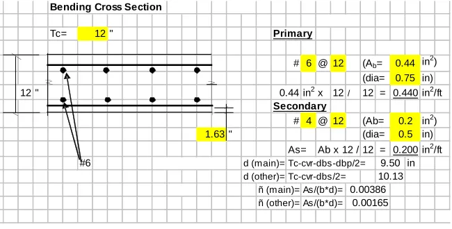
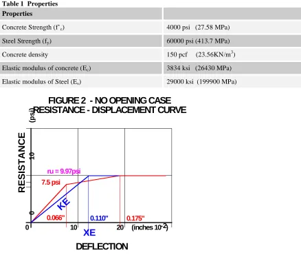
opening as shown in Figure 1. The resistance displacement curve for that structure is given in Figure 2. The resistance of the slab without opening is 9.97 psi (68.74KPa). The properties of the model are as given in Table 1. The slab is reinforced with just the minimum main steel which is #6 at 12 inches (#19 @ 30.5cm) along the span and #4 at 12 inches (#13 @ 30.5cm) temperature steel in the perpendicular direction.
!main dmain !other dother
" # # # # # $
% & & & & & '
Bending Cross Section
Tc= " Primary
# 6 @ 12 (Ab= in
2)
(dia= in)
" in2 x 12/ 12 = in2/ft
Secondary
# 4 @ 12 (Ab= in2)
" (dia= in)
As= Ab x 12 / 12 = in2/ft
#6 d (main)= Tc-cvr-dbs-dbp/2= in
d (other)= Tc-cvr-dbs/2= ñ (main)= As/(b*d)= ñ (other)= As/(b*d)=
0.44 0.75 0.440
0.5 0.200 10.13
0.2 0.44
9.50 12
12
1.63
0.00165 0.00386 :=
15.00 5.000
5.000
5.000 5.000
15.00
LOCATION OF OPENING
P L A N
SECTION A-A
A
A
FIGURE 1: Baseline Model
1.000
Table 1 Properties
Properties
Concrete Strength (f’c) 4000 psi (27.58 MPa)
Steel Strength (fy) 60000 psi (413.7 MPa)
Concrete density 150 pcf (23.56KN/m3) Elastic modulus of concrete (Ec) 3834 ksi (26430 MPa)
Elastic modulus of Steel (Es) 29000 ksi (199900 MPa)
7.5 psi
0.066" 0.175"
0 10 20 (inches 10 )-2
0 10 (psi)
RESISTANCE
DEFLECTION
ru = 9.97psi0.110"
XE
K
E
FIGURE 2 - NO OPENING CASE
RESISTANCE - DISPLACEMENT CURVE
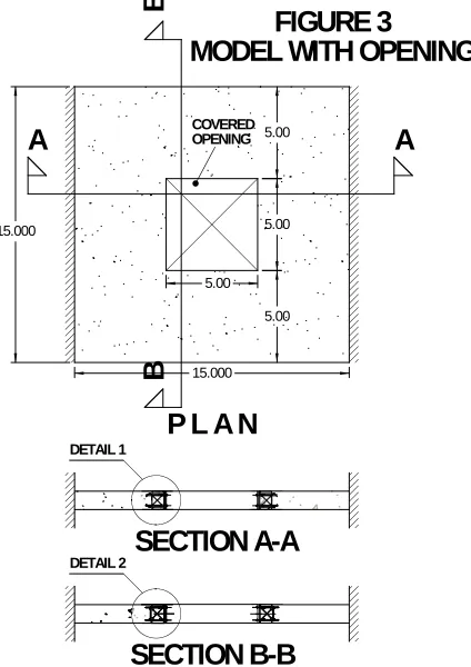
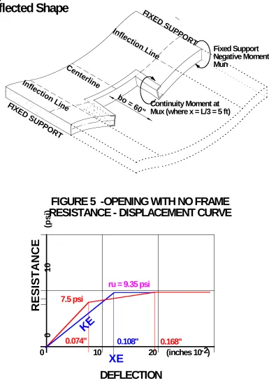
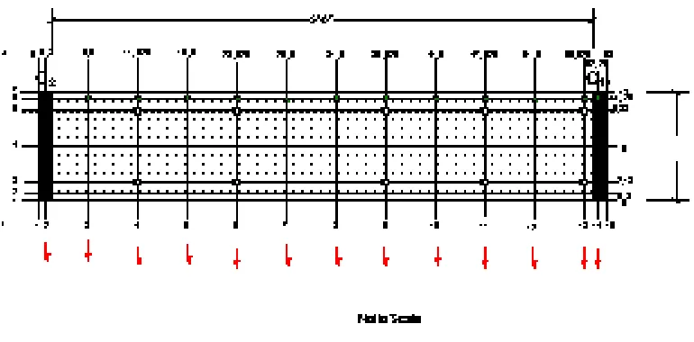
Now let’s introduce the opening as shown in Figure 3. In the typical design the moment Mux shown in
Figure 4, at the edge of the opening goes to zero because the opening interrupts the reinforcement. This results in a decrease in the resistance and stress concentrations in the slab. In this case the resistance goes to 9.73 psi (67.09KPa) as depicted in Figure 5. Note that the slab moves just as much as the case without the opening but at lower load (i.e. resistance). But using the stressed frame the moment at this edge is not zero. Let’s for now assume that moment is the same as the moment that is developed at the same point in the model in Figure 1. That is the moment in the case without the opening. This moment can be computed to be the moment in the elastic model for Figure 1 when the support is fixed and the resistance is re, i.e. the resistance 7.5 psi (51.7KPa) in Figure 2 just
sufficient to create the hinge at the supports, plus the moment in the elastic model for Figure 1 when the support is pinned and the resistance is ru-re (9.97 psi – 7.5 psi) which is typically called rep. This is the additional resistance just
sufficient to create the hinge at mid span of the slab and thus create a collapse mechanism. This moment Mux is
computed from the equation below as 15702 lb-in/in (69.85 KN-cm/cm).
(
)
(
) (
)
!
"
#
$
%
&
+' ( +
( (
=
2 4
4 12
2
1 reBL reBbo L bo repBbo L bo L bo L
ux M
Note that B is the width of the slab, L is span of the slab and bo is the width of the opening.
1. Proportion the frame properties such that the moment of inertia of the slab with the frame is equal to or slightly greater than the moment of inertia of the slab without opening. The moment of inertia of the slab without opening to match is the average moment of inertia. This average moment of inertia takes into account the cracked moment of inertia. For the case of the slab without opening, this moment of inertia is computed as 81.1 in4/in (1329 cm4/cm). To match this moment of inertia with the built up channel shape, the geometric properties of the channel must be chosen such that Iavgnew from following equation is equal to at least 81.1 in4/in (1329 cm4/cm). So
if the flange width, bf, is selected to be 9.25 inches, the channel web thickness, tw, is 1.5 inches,
the channel flange thickness, tf, is 1.5 inches, the depth of the channel, d, is 12 inches and the ratio
of elastic moduli for concrete and reinforcement, n is 7.56, Iavgnew is 81.5 in4/in (1336 cm4/cm).
(
) ( )
!"
!
#
$
!%
!
&
'
(
(
)
*
+
+
,
-.
.
/
0
1
1
2
3
4 4 5 4 + + = 2 2 2 12 3 12 3 2 3 21 d tf
f t w t f b f t w t f b w t d n B avg I B avgnew I
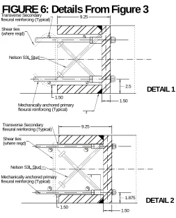
2. Provide rebar couplers to develop the reinforcement at the frame. See details 1 and 2 in Figure 6. 3. And finally provide Nelson studs to take the shear forces at the covered opening safely into the
slab. The nelson studs are assumed to take all the shear forces while the rebars take all the tension at the frame interface. See Figure 6.
The resulting resistance displacement curve shows a resistance that is actually slightly higher, 10.8 psi (74.5 KPa), than the case without opening (Figure 7). How can this be? Well, notice that the stressed frames forces the positive yield lines to occur at the frame edge which is at L/3 instead of the L/2 in the baseline model. Since the moment at the mid-span of the slab is higher than those at the 1/3 span, the yield line at 1/3 span takes slightly more load to occur. But note that this assumes the continuity moment at the edge of the frame obtained is 15702 lb-in/in (69.85 KN-cm/cm). In the next section, we compute what moment if any that develops at the edge of the frame.
15.000 5.00 5.00 5.00 5.00 15.000 COVERED OPENING
P L A N
SECTION A-A
DETAIL 1A
A
B
B
SECTION B-B
DETAIL 2FIGURE 3
FIXED SUPPORT
FIXED SUPPORT
Fixed Support
Negative Moment
Mun
bo
= 60" Continuity Moment at
Mux (where x = L/3 = 5 ft)
Infl
ecti
on
Line
Ce
nte
rlin
e
Infl
ecti
on
Line
Figure 4
Deflected Shape
7.5 psi
0.074"
0.168"
0 10 20 (inches 10 )
-2
0 10 (psi)
RESISTANCE
DEFLECTION
ru = 9.35 psi
0.108"
XE
K
E
1.50 Mechanically anchored primary flexural reinforcing (Typical)
9.25
Shear ties (where reqd)
Nelson S3L Stud
1.50 Transverse Secondary
flexural reinforcing (Typical)
1.50 Mechanically anchored primary flexural reinforcing (Typical)
9.25
Shear ties (where reqd)
Nelson S3L Stud
1.50 Transverse Secondary
flexural reinforcing (Typical)
1.875 2.5
DETAIL 1
DETAIL 2
FIGURE 6: Details From Figure 3
7.5 psi
0.065"
0.214"
0 10 20 (inches 10 )
-2
0
10
(psi)
RESISTANCE
DEFLECTION
ru = 10.8 psi
0.131"
XE
KE
3.0 VALIDATION OF THE STRESSED FRAME
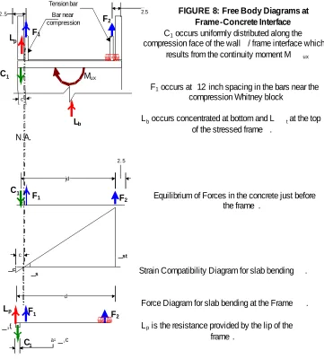
The analysis approach to validate the stressed frame is to analyze the side of the frame parallel to the support as an embedded plate with the continuity moment (Mux) applied. In addition to the moments, the shears at
the perimeter of the covered opening are also applied. So if one drew the schematic of detail 1 in Figure 6 where F1
is the force in the top bar reinforcement in the slab and F2 is the force in the bottom bar reinforcement in the slab.
The equilibrium of forces just before the frame and at the frame, the strain compatibility diagram and the Whitney block is as given in Figure 8 below.
Lb
F1
C1
C1
jd 2. 5
2. 5
C1occurs uniformly distributed along the compression face of the wall / frame interface which
results from the continuity moment M ux
Lb occurs concentrated at bottom and L t at the top of the stressed frame .
F2
Strain Compatibility Diagram for slab bending . Mux
C1
_3fc
_st
= _1c
2.5
N.A. c
Tension bar Bar near compression
F1occurs at 12 inch spacing in the bars near the compression Whitney block
d c
F1 F
2
a
Force Diagram for slab bending at the Frame . Equilibrium of Forces in the concrete just before
the frame . F1
Lp
Lp is the resistance provided by the lip of the frame .
F2
FIGURE 8: Free Body Diagrams at Frame-Concrete Interface Lp
_c _
s
Note that because the neutral axis is to the left of the reinforcement in the compression zone, bar F1 must be
in tension to maintain strain compatibility. Also note that the F2 force is balanced locally at the head of the rebar at the frame. Just before the head the force F2 is balanced by the compression in the Whitney block hence providing the moment capacity Mux. At the frame the compression in the Whitney block must be balanced by the flanges of the frame Lp and by the tension in the bar near the compression block. Using equilibrium of forces and moments,
the maximum compression strain in the slab εc is obtained to be 0.00022. The depth to neutral axis c is obtained to
be 1.15 in. The maximum Force F1 that can be developed at the top bar is therefore 3264.2 lb (14.52 KN) per bar.
The maximum force F2 in the bottom reinforcement is 20.2 kip (89.85 KN). The maximum bearing at the coupler
The embedded plate was analyzed using a simple finite element program called ME035 used for base plates (see Figure 9). It models the channel web and flanges using plate elements, the Nelson studs, A706 rebar, and the concrete as spring elements. The springs are unidirectional i.e. the anchors are tension only springs and the concrete are compression only springs. The axial stiffness (Kb) of the springs representing the anchors can be conservatively taken a
s
AseE/Le. This is the effective cross sectional area of the anchors multiplied by the modulusof elasticity divided by the effective embedment length. The effective length of the reinforcement is the ACI development length of the rebar but the effective length of the Nelson stud is the projected length of the stud normal to the plate. The axial stiffness (Kc) for the concrete springs is computed internally in the program.
Table 2: FEA Input
Table 2 gives the input data for the ME035 run. The results needed from this analysis are the additional
Youngs Modulus (E) = 29000 ksi
Shear Modulus (G) = 11500 ksi
#6 Rebar Properties
diameter (in) 0.75 in
fy (psi) = 60000 psi
f'c (psi) = 4000 psi
depth, Le (in) 17.00 in
Shear Stiffness (lb/in) = 0 lbf/in
Axial Stiffness (lb/in) = 753635.738 lbf/in
Nelson Stud Attached to the channel flanges at 45 degrees
thickness (in) 0.75 in
length (in) 10 in
depth (in) 7.07 in
Shear Stiffness (lb/in) = 1281374.26
Axial Stiffness (lb/in) = 0
Shear Load (R) from Valve = 149.55 lbf/in
Compression Load (lbf/in) = 1953.72 lb/in
x dimension (in) Tributary (in) Comp. (lb) Shear (lb)
0.8 3.65 7131.08 545.86
6.5 5.41 10574.51 809.44
11.625 5.00 9768.60 747.75
16.5 6.00 11722.33 897.30
23.625 5.00 9768.60 747.75
26.5 3.94 7692.78 588.85
31.5 4.56 8913.85 682.32
35.625 5.00 9768.60 747.75
41.5 6.00 11722.33 897.30
47.625 5.00 9768.60 747.75
51.5 6.00 11722.33 897.30
rotations at the opening edge allowed by the frame while the compression forces C1 thru C14 (Figures 8 & 9) are
applied. The flexural stresses in the frame top flange and the force developed in the rebar anchors. The baseline model for the case without opening was analyzed using a finite analysis program (SAP). The slab was modelled using five 3-D solid elements through the thickness in a grid of 12 inches by 12 inches. The edge rotations at the phantom edge where the opening would have been were obtained from the baseline model. These were added to the rotations from the ME035 model to obtain the final rotation for the edge with the stressed frame. A second model was analyzed with the opening but no frame. This gives the rotations at the edge of the opening when there is no restraint. These rotations correspond to the moment at the edge of the opening being zero. For the SAP runs since the rotations at ru are the outputs desired, each model is run twice, once with fixed supports and the load as re and
then with pinned supports with load as rep. The in-plane displacements at the 5 nodes through the slab thickness
were used to establish the edge rotations. The results of the three models are presented next.
4.0 RESULTS
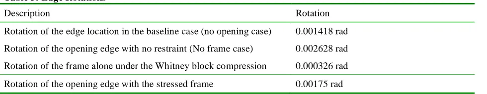
The rotations obtained from the different models are given in Table 3
Table 3: Edge Rotations
Description Rotation
Rotation of the edge location in the baseline case (no opening case) 0.001418 rad
Rotation of the opening edge with no restraint (No frame case) 0.002628 rad
Rotation of the frame alone under the Whitney block compression 0.000326 rad
Rotation of the opening edge with the stressed frame 0.00175 rad
As can be seen from Table 3 the frame provides significant restraint against rotation. At 0.001418 rad the moment developed at the edge location is 15.7 kip-in/in (69.85KN). At 0.002628 rad the moment developed at the opening edge is zero. At the opening edge using the stressed frame the moment is 11.47 kip-in/in (51.02KN).
in in k
in in k
ux M
! !
= "
! !
= 15.7 11.47
001418 . 0 002628 . 0
00175 . 0 002628 . 0
This means that the resistance of the slab with the stressed frame is not 10.8 psi (74.5 KPa) but 10.4 psi (71.7KPa). This value is still higher than the case of the slab without opening. But what about the forces in the top rebars? They must satisfy strain compatibility. From the results of the ME035 run the max anchor load dumped into the top reinforcement is 2586 lb (11.5KN) which is less than the 3264 lb (14.52 KN)computed as the limit per bar. All other limit state checks on the embedded plate are okay such as the stresses in the flanges and the reaction Lb into the side faces of the frame perpendicular to supports. This means that the stressed frame would safely take
the stresses around the opening without stress concentrations in the concrete or the need to add reinforcement around the openings.
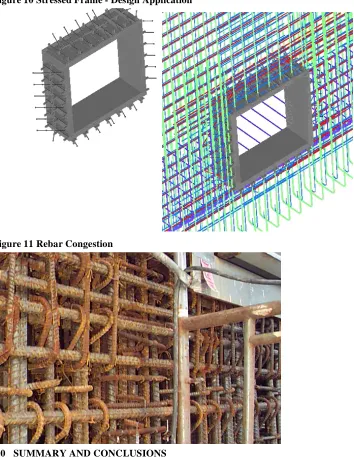
5.0 DESIGN APPLICATIONS
Figure 10 Stressed Frame - Design Application
Figure 11 Rebar Congestion
6.0 SUMMARY AND CONCLUSIONS
The stressed frame concept has been successfully implemented at several projects in the United States. It is however, not without limitation. As can be deduced from the example in this paper, The stressed frame concept has only been tested and used when designing just to ru. That is designing for a ductility of 1 i.e. an elastic response.
This is very appropriate for safety related structures. Using the stressed frame well into the in-elastic range is problematic and fraught with too many assumptions that can not be proven. It is the author’s suggestion to limit the design with this concept to a ductility of 0.9 for chambers designed to mitigate accidental explosions. When designing for a wall or slab with the stressed frame, it is conservative to design for wall or slab as if there were no openings thus simplifying the analysis greatly.
REFERENCE