Available online:
http://edupediapublications.org/journals/index.php/IJR/
P a g e | 6 9 7Design and Simulation of Thermal Analysis of
Inline Engine Components
Ms. R. Jayasri
1, Mr. G. Venkateswara Rao
21
PG Student in Thermal Engineering, BVC Engineering College, Odalarevu.
2Assoc. Prof, Dept of Mechanical Engineering, BVC Engineering College, Odalarevu.
A bs tract :
The inline four cylinder engine or straight four engine is an internal combustion engine with all four cylinders mounted in a line, or plane on the housing. The one bank of cylinders could also be familiarized in either a vertical or associate degree simple machine with all the pistons driving a typical shaft. Wherever it's inclined, it's generally known as a slant-four. Specification chart or once an abbreviation is employed, associate degree in line four engine is listed either as I4 or L4.
The main objective of the project is a way to design the major components of inline four cylinder engine using SOLIDWORKS/DESIGN with standard dimensions. The components which are developed in SOLIDWORKS are also analyzed in it using simulation tool. The thermal analysis of piston, valve, camshaft and crankshaft are performed at 800 kelvin thermal loading and therefore the results of temperature distribution of the elements are to be evaluated. Finally the thermal analysis results of the elements are compared with different materials.
In present work, Aluminum Alloy 1060 and Alloy Steel are considered. By comparing the temperature variations of all the components for both materials we can conclude the best suited material. Keywords
Four inline engine, solidworks, piston, valve, crankshaft, camshaft, simulation.
INTRODUCTION
An internal combustion engine is defined as an engine in which the chemical energy of the fuel is released inside the engine and used directly for mechanical work, as opposed to an external combustion engine in which a separate combustor is used to burn the fuel. The internal combustion engine was conceived and developed in the late 1800s. It has had a significant impact on society, and is considered
one of the most significant inventions of the last century. The internal combustion engine has been the foundation for the successful development of many commercial technologies. For example, consider how this type of engine has transformed the transportation industry, allowing the invention and improvement of automobiles, trucks, airplanes and trains.
Internal combustion engines can deliver power in the range from 0.01 kW to 20x103 kW, depending on their displacement. The complete in the market place with electric motors, gas turbines and steam engines. The major applications are in the vehicle (automobile and truck), railroad, marine, aircraft, home use and stationary areas. The vast majority of internal combustion engines are produced for vehicular applications, requiring a power output on the order of 102 kW. Next to that internal combustion engines have become the dominant prime mover technology in several areas. For example, in 1900 most automobiles were steam or electrically powered, but by 1900 most automobiles were powered by gasoline engines. As of year 2000, in the United States alone there are about 200 million motor vehicles powered by internal combustion engines. In 1900, steam engines were used to power ships and railroad locomotives; today two- and four-stoke diesel engines are used. Prior to 1950, aircraft relied almost exclusively on the pistons engines. Today gas turbines are the power plant used in large planes, and piston engines continue to dominate the market in small planes. The adoption and continued use of the internal combustion engine in different application areas has resulted from its relatively low cost, favourable power to weight ratio, high efficiency, and relatively simple and robust operating characteristics.
Available online:
http://edupediapublications.org/journals/index.php/IJR/
P a g e | 6 9 8 between a modern day engine and one built 100years ago are the thermal efficiency and the emission level. For many years, internal combustion engine research was aimed at improving thermal efficiency and reducing noise and vibration. As a consequence, the thermal efficiency has increased from about 10% to values as high as 50%. Since 1970, with recognition of the importance of air quality, there has also been a great deal of work devoted to reducing emissions from engines. Currently, emission control requirements are one of the major factors in the design and operation of internal combustion engines.
INLINE FOUR CYLINDER ENGINE
The Inline-four engine or Straight-four is an internal combustion engine with all four cylinders. All four cylinders are mounted in a straight line along one crankshaft. It can be powered by different types of fuels, including gasoline, diesel and natural gas.
The single bank of cylinders may be in a vertical direction (straight up), or at an angle. When the cylinders are mounted at an angle, it is sometimes called a slant-four. When listed as an abbreviation, an inline-four engine is listed either as I4 or L4 (for longitudinal). L4 is often used to avoid confusion between the digit 1 and the letter I.
The inline-four layout is a mechanically simple engine. It has a natural basic engine balance. It is smoother than one, two, and three cylinder engines. This makes it popular for economy cars. It does have a problem with secondary engine balance. This causes minor vibrations in smaller engines. These vibrations become worse as engine size and power increase. The more powerful engines used in larger cars use different an engine layout to avoid this problem.
LITERA TURE REVIEW
The Engine cylinder is one of the major automobile components, which is subjected to high temperature variations and thermal stresses. In order to cool the cylinder, fins are provided on the surface of the cylinder to increase the rate of heat transfer. By doing thermal analysis on the engine cylinder fins, it is helpful to know the heat dissipation inside the cylinder. We know that, by increasing the surface area we can increase the heat dissipation rate, so designing such a large complex engine is very difficult. The objective of the author is to analyze the
thermal properties by varying geometry, material and thickness of cylinder fins using ansys work bench. Transient thermal analysis determines temperatures and other thermal quantities that vary over time. The variation of temperature distribution over time is of interest in many applications such as in cooling. The accurate thermal simulation could permit critical design parameters to be identified for improved life. Presently Material used for manufacturing cylinder fin body is Aluminum Alloy A204 which has thermal conductivity of 110-150W/mk. Analysis is carried out for cylinder fins using this material and also using Aluminum alloy 6061 which have higher thermal conductivities.[1]
In IC engine Piston is one of the most important and complex part, so it is important to maintain Piston in good condition in order to maintain the proper functioning of the engine. Piston mainly fails due to thermal Conditions. So as to search out proper thermal distribution different Piston Materials are considered.[2] Engine heat transfer and cooling is always been a crucial area of interest for improvement of engine performance.CFD methods and tools used today provide clearer and more detailed data on temperature, flow and pressure variation. The main objective of the study is to carry heat transfer as well as flow analysis of existing cooling jacket of 6-cylinder turbo after-cooled medium duty diesel engine and then investigate the factors affecting cooling performance to optimize the said parameters through steady state CFD analysis and validate them with experimental results.[3]
A four stroke four cylinder in‐line petrol engine is modeled to estimate various performance parameters. The solution is based on tribology and dynamics principle. The detailed parameters related to engine friction and lubrication are computed numerically for the 1‐3‐4‐2 engine firing order. The numerical method is based on finite difference method that solves coupled Reynolds Equation and Energy equation. Output includes the film thickness, friction force, friction power loss and temperature rise in ring liner conjunction in all four cylinders[4].
Available online:
http://edupediapublications.org/journals/index.php/IJR/
P a g e | 6 9 9 requirement of weight reduction the material selectedfor design of cylinder and cylinder head is Aluminum alloy that is LM-13. The cylinder bore coating using NIKASIL coating was done to improve strength of cylinder with minimum weight.[5]
The importance of heat transfer in design of four stroke engine is important to make sure the engine will perform to expectation during actual working conditions. For this a prediction is done on the various heat distributions that might occur during a normal operation of the engine. The finite element model was evolved with many boundary conditions that are predicted from theoretical studies. This is to see the general heat transfer of the engine and whether or not the engine will withstand the thermal loads occurring during the theoretical operation. Assumptions are made by approximating temperature to the actual operating condition of the engine. Heat transfer was modeled with conduction and convection as the main source of heat transfer and neglecting radiation. The values are to be verified when the actual engine is operating with correct boundary conditions. It is hoped that the engine will not come to the boundary applied as it is assumed very high compared to actual condition. The study is a transient study with assumption that the engine is running at 6000 rpm for 60 seconds and generating the boundary heat from theoretical calculations. First thermal analysis was done and analyzed the temperature distribution over the fin area. In the second stage structural analysis was carried out using the thermal loads obtained in the first stage. Three different types of materials were taken for analysis.[6]
Successful numerical simulations can reveal important flow characteristics and information which are extremely difficult to obtain experimentally. Two- and three-dimensional (3-D) numerical simulations of cross-flow around four cylinders in an in-line square configuration are performed using a finite-volume method. There is a large discrepancy between 2-D simulation and flow visualization results. A probable cause could be the strong 3-D effect at the ends of the cylinder at low H/D. It was found that, for an in-line square configuration at critical L/D and when H/D is lower than a certain value, 3-D effects are very significant at the ends of the cylinders [7].
Braking system represents one of the most fundamental safety critical components in modern vehicles. Brake absorbs kinetic energy of the rotating
parts (Wheels) and the energy is dissipated in the form of heat energy to the surrounding atmosphere. It decelerates or stops the vehicle. When brake is applied to the disc brake it is subjected to high stress, thus it may suffer structural and wear issues. Hence for the better performance, structural, stress and the thermal analysis is preferred to choose low stress material. Here the modelling and analyse stress concentration, structural deformation and thermal gradient of disc brake has been done. The disc brake is designed by using Solidworks and analysis is done by ANSYS workbench.[8]
Based on the literature review, it is understood that the design and thermal analysis of major equipments like engines and mechanical braking systems are suffering from thermal conductivity. So that it is essential to study thermal analysis of various components of engines and braking systems in order to provide proper cooling systems. In the literature review the authors investigated the thermal behavior of various elements using different software’s like ANSYS, steady state CFD analysis, CAD tool etc. In this study designing of major components of four In-line cylinder are designed and simulated (Thermal Analysis) using SOLIDWORKS software.
INTRODUCTION TO SOLIDW ORKS
Solid Works is mechanical design automation software that takes advantage of the familiar Microsoft Windows graphical user interface. It is an easy-to-learn tool which makes it possible for mechanical designers to quickly sketch ideas, experiment with features and dimensions, and produce models and detailed drawings.
A Solid Works model consists of parts, assemblies, and drawings.
Typically, we begin with a sketch, create a base feature, and then add more features to the model. (One can also begin with an imported surface or solid geometry).
We are free to refine our design by adding, changing, or reordering features.
Available online:
http://edupediapublications.org/journals/index.php/IJR/
P a g e | 7 0 0 We can generate drawings or assemblies at anytime in the design process.
The SolidWorks software lets us customize functionality to suit our needs.
SIM ULA TION STUDIES:
SolidWorks Simulation is a design analysis system fully integrated with SolidWorks. SolidWorks Simulation provides simulation solutions for linear and nonlinear static, frequency, buckling, thermal, fatigue, pressure vessel, drop test, linear and nonlinear dynamic, and optimization analyses.
Powered by fast and accurate solvers, SolidWorks Simulation enables you to solve large problems intuitively while you design. SolidWorks Simulation comes in two bundles: SolidWorks Simulation Professional and SolidWorks Simulation Premium to satisfy your analysis needs. SolidWorks Simulation shortens time to market by saving time and effort in searching for the optimum design. It is important to verify your input before running a study:
Verify that you have assigned the proper material for each component/shell.
Verify that you have specified the proper study properties.
Verify that you have specified the proper loads and restraints.
Verify the mesh and make sure it corresponds to the desired mesh options.
Ru n n in g a Stu d y
When you run a study, the software calculates the results based on the specified input for materials, restraints, loads, and mesh.
You can choose to run a study automatically after meshing it by checking the Run (solve) the analysis option in the Mesh Property Manager.
When you run one or multiple studies, they run as background processes. Right-click the study and select Run. Simulation continues to run in the background after the SOLIDWORKS session is ended. When the simulation completes, results are stored in the designated directory.
To run multiple studies, on the Simulation
Command Manager, from the Run tab, click Run All Studies.
To select which studies to run from the list of available studies, click the down arrow on Run (Simulation Command Manager) and select Run Specified Studies.
Ru n Sp ecified Stu d ies
You can select which Simulation studies to run from the list of all Simulation studies defined in a part or assembly document. The selected Simulation studies are run automatically in a batch mode. To open the Run Specified Studies dialog box: Click Simulation > Run > Run Specified
Studies, or
Click the down arrow on Run this study (Simulation Command Manager) and select Run Specified Studies.
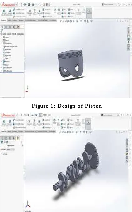
DESIGN OF COM PONENTS
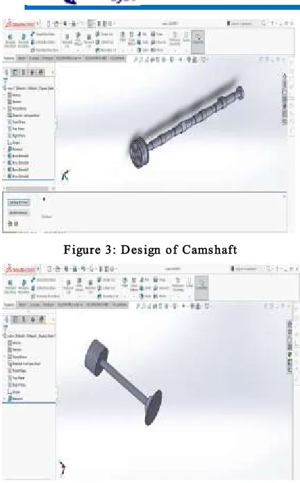
The components are designed according to the procedure and specification which are given in machine design and data hand books. The dimensions are calculated in terms of SI Units. The parts like piston, crankshaft, camshaft, valve are modeled using DESIGN/SOLIDW ORKS.
Figure 1: Design of Pist on
Available online:
http://edupediapublications.org/journals/index.php/IJR/
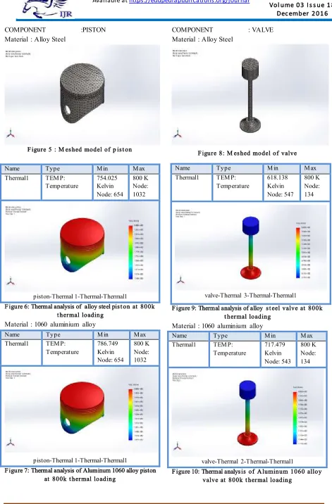
P a g e | 7 0 1Figure 3: Design of Camshaft
Figure 4: Design of Valve
THERM A L A NA LYSIS
Thermal analysis can be performed in various ways using the SolidWorks Simulation and SolidWorks Flow Simulation packages. Thermal analysis entails defining thermal conditions and analyzing the stresses that develop in components due to thermal expansion.
Th ermal M o d u le : The Thermal module included in the SolidWorks Simulation Professional product suite allows one to study temperature distribution and heat flow in a mechanism due to conduction, convection, and radiation effects. Outputs from this module can be coupled with a linear static study to compute thermal stress.
Selectio n o f material: Conduction effects are automatically taken into account during the analysis and are attributed to the thermal conductivity material property. The required material can be selected from the “A p ply M aterial” Tab provided on the solidworks/simulation toolbar.
Lin ear/No n lin ear Stat ic – Th ermal Stres s : Thermal stress analysis can be performed using the Linear Static and Nonlinear Static modules included in SolidWorks Simulation/SolidWorks Simulation Premium. One of the load types available in a static study is Temperature. This allows a user to specify a specific temperature on different entity types.
Rad iatio n M o d u le: Radiation effects (heat transfer caused by electromagnetic waves) are defined using a surface boundary condition. The presence of radiation is accounted for by specifying an Ambient Temperature, Emissivity and View Factor input. The value of the ambient temperature can be modified using a time curve, while the value of emissivity can be adjusted using a temperature curve.
M es h in g : The program automatically creates a shell mesh for sheet-metals with uniform thicknesses (except drop test study) and surface geometries. For sheet metals the mesh is automatically created at the mid-surface. The program extracts the shell thickness from the thickness of the sheet metal.
Ru n Simulation: When you run a study, the software calculates the results based on the specified input for materials, restraints, loads, and mesh. You can choose to run a study automatically after meshing it by checking the Run (solve) the analysis option in the Mesh Property Manager. When you run one or multiple studies, they run as background processes. Right-click the study and select Run. Simulation continues to run in the background after the SOLIDWORKS session is ended. When the simulation completes, results are stored in the designated directory.
Available online:
http://edupediapublications.org/journals/index.php/IJR/
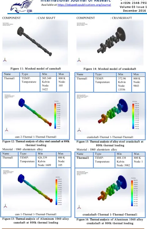
P a g e | 7 0 2COMPONENT :PISTON
Material : Alloy Steel
Figure 5 : M eshed model of p ist on
Name Type Min Max Thermal1 TEMP:
Temperature
754.025 Kelvin Node: 654
800 K Node: 1032
piston-Thermal 1-Thermal-Thermal1
Figure 6: Thermal analysis of alloy steel pist on at 800k t hermal loading
Material : 1060 aluminium alloy
Name Type Min Max Thermal1 TEMP:
Temperature
786.749 Kelvin Node: 654
800 K Node: 1032
piston-Thermal 1-Thermal-Thermal1
Figure 7: Thermal analysis of Aluminum 1060 alloy piston at 800k t hermal loading
COMPONENT : VALVE
Material : Alloy Steel
Figure 8: M eshed model of valve
Figure 9: Thermal analysis of alloy st eel valve at 800k t hermal loading
Material : 1060 aluminium alloy
Name Type Min Max Thermal1 TEMP:
Temperature
717.479 Kelvin Node: 543
800 K Node: 134
valve-Thermal 2-Thermal-Thermal1
Figure 10: Thermal analysis of Aluminum 1060 alloy valve at 800k t hermal loading
Name Type Min Max Thermal1 TEMP:
Temperature
618.138 Kelvin Node: 547
800 K Node: 134
Available online:
http://edupediapublications.org/journals/index.php/IJR/
P a g e | 7 0 3COMPONENT : CAM SHAFT
Figure 11: M eshed model of camshaft Name Type Min Max Thermal1 TEMP:
Temperature
505.349 Kelvin Node: 1622
800 K Node: 105
cam 2-Thermal 1-Thermal-Thermal1
Figure 12: Thermal analysis of alloy steel camshaft at 800k t hermal loading
Material : 1060 aluminium alloy
Name Type Min Max Thermal1 TEMP:
Temperature
626.339 Kelvin Node: 1609
800 K Node: 105
cam 1-Thermal 1-Thermal-Thermal1
Figure 13: Thermal analysis of Aluminum 1060 alloy camshaft at 800k t hermal loading
COMPONENT : CRANKSHAFT
Figure 14: M eshed model of crankshaft Name Type Min Max Thermal1 TEMP:
Temperature
372.96 Kelvin Node: 13556
800 K Node: 9843
crankshaft-Thermal 1-Thermal-Thermal1 Figure 15: Thermal analysis of alloy st eel crankshaft at
800k t hermal loading
Material : 1060 aluminium alloy
Name Type Min Max T hermal1 TEMP:
Temperature
488.138 Kelvin Node: 3982
800 K Node: 1
crankshaft -T hermal 1-T hermal-T hermal1 Figure 16: Thermal analysis of Aluminum 1060 alloy
Available online:
http://edupediapublications.org/journals/index.php/IJR/
P a g e | 7 0 4 Thermal analysis of the major componentslike Piston, Valve, Crankshaft and Camshaft are analyzed at 800K temperature and the radiation affect are studied. The minimum and maximum temperatures of various components with Alloy Steel and 1060 Aluminum Alloy are tabulated as below. Tab le 1: Sh o win g th e co mp aris o n o f d ifferen t
co mp o n en ts with d ifferen t materials
Materi al
Pist on Cranksha
ft Cam shaft Valve
Ma x. [k] Mi n. [k] Ma x [k] Mi n. [k] Ma x. [k] Mi n. [k] Ma x. [k] Mi n. [k] Alloy
st eel 800 754 800 372 800 505 800 618 1060
alloy 800 786 800 488 800 626 800 717
From above results, it is clear that thermal deformation of all the components increased from bottom to top. The components with material Aluminum Alloy 1060 has less temperature variations compared to the components with material Alloy Steel. This can be seen clearly in the above shown table. Therefore we can conclude that the components with material Aluminum Alloy 1060 are better compared with material Alloy Steel.
CONCLUSION
Internal Combustion engine is one of the most important inventions of the last Century. It has been developed in the late 1800s and from there on it has had a significant impact on our society. It has been and will remain for foreseeable future a vital and active area of engineer research.
Using a CAD tool called SOLIDWORKS, Four Inline Cylinder Engine components are developed including few sub-assemblies they are Crank Shaft, Piston, Valves, Cam Shaft. The main objective of this project is to know the designing process using SOLIDWORKS and also preparing components. This project is deals with the Modelling and analysis of these engine components. And
analysis is done using SOLIDWORKS/
SIMULATION. Using this software, here we chose different type of materials for every component which are developed in SIMULATION/DESIGN tool. The materials are not existing material and materials are chosen which are better than existing
materials. The main objective of analysis is to show the heat transformations from one component to another component by applying boundary conditions and thermal loads are applied. This process is done for Crank Shaft, Piston, Valves, Cam Shaft components. These Analysis process is done in every manufacturing industries before assembling.
In present work, Alloy Steel and Aluminium Alloy 1060 are considered. The material which are chosen are better in weight and thermal conduction. The results shows, the components with material Aluminium Alloy 1060 is better when compared to the components with material Alloy Steel since it has less temperature variation.
REFERENCES
1. P. Sai Chaitanya, B. Suneela Rani, K. Vijaya Kumar, “Thermal Analysis of Engine Cylinder Fin by Varying Its Geometry and Material” IOSR-JMCE e-ISSN: 2278-1684,p-e-ISSN: 2320-334X, Volume 11, Issue 6 Ver. I (Nov- Dec. 2014), PP 37-44.
2. B.A.Devan1, G.Ravindra Reddy, “Thermal analysis of Aluminium alloy Piston” (IJETER), Vol. 3 No.6, Pages : 511 - 515 (2015).
3. Amit V. Paratwar, D.B Hulwan, “Surface Temperature Prediction and Thermal Analysis of Cylinder Head in Diesel Engine “, International Journal of Engineering Research and Applications (IJERA) ISSN: 2248-9622 Vol. 3, Issue 4, Jul-Aug 2013, pp.892-902.
4. P.C. Mishra, “Modelling for Friction of Four Stroke Four Cylinder in‐Line Petrol Engine”, Tribology in Industry, Vol. 35, No. 3 (2013) 237‐245
5. Ravindra R. Navthar, Prashant A. Narwade, “Design and Analysis of Cylinder and Cylinder head of 4-stroke SI Engine for weight reduction”, International Journal of Engineering Science and Technology (IJEST), ISSN : 0975-5462 Vol. 4 No.03 pp. 847-853. 6. Mr. A. Raj Kumar, Dr. G.Janardhana Raju, Dr. G. Amarendar Rao, “Heat Transfer Analysis In The Cylinder Head Of A Four-Stroke Si Engine”
International Journal of Engineering Research & Technology ISSN: 2278-0181, Vol. 2 Issue 5, 2013 7. K. Lama, W.Q. Gongb, R.M.C. Soa,“Numerical
simulation of cross-flow around four cylinders in an in-line square configuration” Journal of Fluids and Structures 24 (2008) 34–57.
8. Rakesh Jaiswal, Anupam Raj Jha, Anush Karki, “structural and thermal analysis of disc brake using solidworks and ansys” International Journal of Mechanical Engineering and Technology (IJMET)
Volume 7, Issue 1, Jan-Feb 2016, pp. 67-77,
9. Colin R. Ferguson (1986), “Internal Combustion Engine Applied Thermosciences”John B. Heywood (1988), “Internal Combustion Engine Fundamentals” 10. Richard Stone (1999), “Introduction to Internal
Combustion Engines” (3rd edition)