International Journal of Research (IJR)
e-ISSN: 2348-6848, p- ISSN: 2348-795X Volume 2, Issue 08, August 2015 Available at http://internationaljournalofresearch.org
Mobile based vehicle control and obstacle detection using
IR Sensor
1
Eppa sneha;
2P. Venkateshwarlu&
3M. Shyam sundar
1. M.Tech, SVS Institute of Technology, Warangal, Hasanparthy, Bheemaram, Hanamkonda, Telangana 506015.
2.Asst. Professor, SVS Institute of Technology, Warangal, Hasanparthy, Bheemaram, Hanamkonda, Telangana 506015.
3. Associate Prof, SVS Institute of Technology, Warangal, Hasanparthy, Bheemaram, Hanamkonda, Telangana 506015.
ABSTRACT:
An autonomous mobile vehicle needs to be developed to allow the vehicle to reach the desired destination using tracking and obstacle detection schemes. This paper concentrates on the vehicle navigation and obstacle detection conventionally; wireless-controlled robots use RF circuits, which have the drawbacks of limited working range, limited frequency range and limited control. Use of a mobile phone for robotic control can overcome these limitations. It provides the advantages of robust control, working range as large as the coverage area of the service provider, no interference with other controllers and up to twelve controls. Although the appearance and capabilities of robots vary vastly, all robots share the features of a mechanical, movable structure under some form of control. The control of robot involves three distinct phase namely perception, processing and action. Generally, the preceptors are sensors mounted on the robot, processing is done by the on-board microcontroller or processor, and the task (action) is performed using motors or with some other actuators.
1. INTRODUCTION
International Journal of Research (IJR)
e-ISSN: 2348-6848, p- ISSN: 2348-795X Volume 2, Issue 08, August 2015 Available at http://internationaljournalofresearch.org
construction and working are in section III and IV. The applications and future scope of the project is explained in the further sections.
2. TECHNOLOGY USED
2.1 Dual-Tone Multi-Frequency (DTMF)
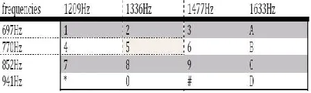
Dual-tone multi-frequency (DTMF) signaling is used for telecommunication signaling over analog telephone lines in the voice-frequency band between telephone handset and other communications devices and the switching center. The version of DTMF used for telephone tone dialing is known by the trademarked term Touch-Tone (canceled March 13, 1984), and is standardized by ITU-T Recommendation It is also known in the UK as MF4. Other multi-frequency systems are used for signaling internal to the telephone network [1]. 2.2 Telephone Keypad The contemporary keypad is laid out in a 3×4grid, although the original DTMF keypad had an additional column for four now-defunct menu selector keys. When used to dial a telephone number, pressing a single key will produce a pitch consisting of two simultaneous pure tone sinusoidal frequencies. The row in which the key appears determines the low frequency, and the column determines the high frequency [1].
For example, pressing the '1' key will result in a sound composed of both a 697 and a 1209 hertz (Hz) tone as shown in Fig. 2.1. The original keypads had levers inside, so
each button activated two contacts. The multiple tones are the reason for calling the system multi frequency. These tones are then decoded by the switching center to determine which key was pressed [1].
2.3 Tones #, *, A, B, C, and D
The engineers had envisioned phones being used to access computers, and surveyed a number of companies to see what they would need for this role. This led to the addition of the number sign (#, sometimes called 'octothorpe' in this context) and asterisk or "star" (*) keys as well as a group of keys for menu selection: A, B, C and D. In the end, the lettered keys were dropped from most phones, and it was many years before these keys became widely used for vertical service codes such as *67 in the United States and Canada to suppress caller ID.
The U.S. military also used the letters, relabeled, in their now defunct Autovon phone system. Here they were used before existing calls if need be. The idea was to allow important traffic to get through every time. The levels of priority available were Flash Override (A), Flash (B), Immediate (C), and Priority (D), with Flash Override being the highest priority [1].
3. CIRCUIT DESIGN
International Journal of Research (IJR)
e-ISSN: 2348-6848, p- ISSN: 2348-795X Volume 2, Issue 08, August 2015 Available at http://internationaljournalofresearch.org
3.1 Motor Driver
The L293D (Fig. 3.2) is a quad, high-current, half-H driver designed to provide bidirectional drive currents of up to 600 mA at voltages from 4.5V to 36V. It makes it easier to drive the DC motors.
driver 1 through driver 4. Drivers 1 and 2, and drivers 3 and 4 are enabled by enable pin 1 (EN1) and pin 9 (EN2), respectively. When enable input EN1 (pin 1) is high, drivers 1 and 2 are enabled and the outputs corresponding to their inputs are active. Similarly, enable input EN2 (pin 9) enables drivers 3 and 4 [2], [3].
3.2 DTMF Decoder
An MT8870 (Fig. 3.3) series DTMF decoder is used here. All types of the MT8870 series use digital counting techniques to detect and decode all the 16 DTMF tone pairs into a 4-bit code output. The built-in dial tone rejection circuit eliminates the need for pre-filtering. When the input signal given at pin 2
(IN-) in single-ended input configuration is recognized to be effective, the correct 4-bit decode signal of the DTMF tone is transferred to Q1 (pin 11) through Q4 (pin 14) outputs D0 through D3 outputs of the DTMF decoder (IC1) are connected to port pins of Microcontroller [4].
3.3. ARM:
International Journal of Research (IJR)
e-ISSN: 2348-6848, p- ISSN: 2348-795X Volume 2, Issue 08, August 2015 Available at http://internationaljournalofresearch.org
support for a 64-bit address space and 64-bit arithmetic. Instructions for ARM Holdings' cores have 32 bits wide fixed-length instructions, but later versions of the architecture also support a variable-length instruction set that provides both 32 and 16 bits wide instructions for improved code density. Some cores can also provide hardware execution of Java bytecodes.
ARM Holdings licenses the chip designs and the ARM instruction set architectures to third parties, who design their own products that implement one of those architectures—including systems-on-chips (SoC) that incorporate memory, interfaces, radios, etc.
Obstacle: Circuit design mainly consists of two parts-
a) Sensor part
b) Control board part
a) Sensor part:-The sensors used in this robot are Infrared sensor, consisting two part infrared signal generator and the IR receiver designed in single PCB. There are two sensors are used as left side sensor and right side sensor and two sensors are used to sense the obstacle on left and right side.
IR Generator:-This is a Mono stable
multivibrat or using NE555 IC generating Infrared Signal of 38 KHz frequency for better determination of the object. By using a variable resistance we can adjust the frequency of the IR signal, detector TSOP1738, gives a high output
IR Detector:-IR detector circuit is a circuit
which gives a low output in absence of IR signal When some obstacle come in path IR signal reflected back and fall onto the IR
detector. In such a way that obstacle are detected.
4 CONSTRUCTION
While constructing any robot, one major mechanical constraint is the number of motors being used. You can have either a two- wheel drive or a four-wheel drive. Though four-wheel drive is more complex than two-wheel drive, it provides more torque and good control. Two-wheel drive, on the other hand, is very easy to construct. Motors are fixed to the bottom of this sheet and the circuit is affixed firmly on top of the sheet. A
International Journal of Research (IJR)
e-ISSN: 2348-6848, p- ISSN: 2348-795X Volume 2, Issue 08, August 2015 Available at http://internationaljournalofresearch.org
actions. The DTMF tones thus produced are received by the cell phone in the robot. These tones are fed to the circuit by the headset of the cell phone. The MT8870 decodes the received tone and sends the equivalent binary number to the microcontroller. According to the program in the microcontroller, the robot starts moving. When key ‘2’ is pressed on the mobile phone, the microcontroller outputs for forward motion. When you press key ‘8’ on your mobile phone, the microcontroller outputs for Reverse motion. When you press key ‘4’ on your mobile phone, the microcontroller outputs for Left direction motion. When you press key ‘6’ on your mobile phone, the microcontroller outputs for Right direction motion. Four keys on the keypad are used for motion control of the robotic car. The rest can be configured to serve various other purposes depending on the area of application of the vehicle.
5 APPLICATION 5.1 Scientific Use
Remote control vehicles have various scientific uses including hazardous environments. Majority of the probes to the other planets in our solar system have been remote control vehicles, although some of the more recent ones were partially autonomous. The sophistication of these devices has fueled greater debate on the need for manned spaceflight and exploration. The Voyager I spacecraft is the first craft of any kind to leave the solar system. The Martian explorers Spirit and Opportunity have provided continuous data about the surface of Mars since January 3, 2004.
5.2 Military and Law Enforcement Use
Military usage of remotely controlled military vehicles dates back the first half of 20th century. Soviet Red Army used remotely controlled Tele tanks during 1930s in the Winter War and early stage of World War II. There were also remotely controlled cutters and experimental remotely controlled planes in the Red Army.
Remote control vehicles are used in law enforcement and military engagements for some of the same reasons. Exposure to hazards is mitigated to the person who operates the vehicle from a location of relative safety. Remote controlled vehicles are used by many police department bomb-squads to defuse or detonate explosives.
Unmanned Aerial Vehicles (UAVs) have undergone a dramatic evolution in capability in the past decade. Early UAV's were capable of reconnaissance missions alone and then only with a limited range. Current UAV's can hover around possible targets until they are positively identified before releasing their payload of weaponry. Backpack sized UAV's will provide ground troops with over the horizon surveillance capabilities.
7 CONCLUSION
International Journal of Research (IJR)
e-ISSN: 2348-6848, p- ISSN: 2348-795X Volume 2, Issue 08, August 2015 Available at http://internationaljournalofresearch.org
dependant on the area of application of the RCV.
8 REFERENCES
[1] L. Schenker, "Pushbutton Calling with a Two- Group Voice-Frequency Code", The Bell System Technical Journal, 39(1), 1960, 235–255, ISSN 0005-8580
[2] S. A. Nasar, I. Boldea, Electric Drives
(CRC/Taylor and Francis, 2006)
[3] V. Subramanyam, Electric Drives (Mc-Graw Hill, 1996)
[4] Edwin Wise, Robotics Demystified (Mc-Graw Hill, 2005)
[5] K. J. Ayala, 8051 Microcontroller