ISSN (Print) : 2320 – 3765 ISSN (Online): 2278 – 8875
I
nternational
J
ournal of
A
dvanced
R
esearch in
E
lectrical,
E
lectronics and
I
nstrumentation
E
ngineering
(An ISO 3297: 2007 Certified Organization)
Vol. 5, Issue 8, August 2016
Power Factor Improvement Using PI
Controlled DSTATCOM
Poornima S1 , Jois K George2
PG Student [PEPS], Dept. of EEE, KITS Engineering College, Kottayam, Kerala, India1 Assistant Professor, Dept. of EEE, KITS Engineering College, Kottayam, Kerala, India2
ABSTRACT: Power quality disturbances are an important matter in today’s distribution system. It may lead to tripping and malfunctioning of sensitive equipments in distribution system. A Distribution Static Synchronous Compensator (DSTATCOM) is introduced here to solve the power quality issues by injecting or absorbing real and reactive power to the point of Common Coupling (PCC). This study presents how the DSTATCOM can be used to compensate the power factor problems and thus to improve the distribution system performances by using PI and Hysteresis controllers. A 6 pulse Voltage Source Inverter based D-STATCOM with PI
control algorithms are designed and developed using MATLAB/Simulink simulation program. The complete model is subjected to, first without DSTATCOM and then with it. The results obtained in both the cases are analysed. Based on this analysis the capability of DSTATCOM to mitigate the power quality disturbances
is validated.
KEYWORDS: - Distribution System, DSTATCOM, Proportional Integral Controller, Power Quality, VSI.
I. INTRODUCTION
Maintaining power quality in distribution system is very essential in today’s scenario because of the increase in wide variety of loads that is connected the power system. Inductive loads require reactive power for their magnetization and if the reactive power is consumed from the grid decrease in voltage occurs.So, it is necessary to compensate required reactive power. The quality of electric power available to the end user is very important. Proliferation of wide variety of electronic device in to the electric power system has caused the issue of power quality Power quality means different thing to different people. It actually refers to the faithfulness of system to supply and maintain load voltage as pure sinusoidal waveform at rated voltage and frequency .The possible causes of power quality issues may be because of voltage sag, voltage swell, under voltage, over voltage, interruption, harmonic distortion, noise FACTS devices have been proposed for fast dynamic voltage, impedance, and phase angle control on high-voltage ac lines. The advent of such devices has given rise to family of power electronic equipment to control the power system dynamic performance. These include static synchronous compensator (STATCOM), static synchronous series compensator (SSSC), and Unified Power Flow Controller (UPFC). The use of series and shunt compensators replaced conventional reactive compensators, such as the Thyristor Switched Capacitor (TSC) and Thyristor Controlled Reactor (TCR). The application of this technology opened better opportunities for an appropriate transmission and distribution control. Static synchronous compensator (STATCOM) is one of the FACTS devices which play a vital role in controlling the reactive power in power system. . Due to the abundant use of nonlinear loads, nonlinear controllers are more preferred than linear controllers. Now days a new concept of custom power devices is used. There are three types of custom power devices such as DVR, DSTATCOM and
UPQC .Here DSTATCOM is used for power factor correction
A. POWER QUALITY DISTURBANCES
Improved power quality is the driving force for today’s modern industry Poor power quality is the main reason of unwanted equipment trips or shut downs The following parameters of supply voltage are influenced by disturbances
Frequency
ISSN (Print) : 2320 – 3765 ISSN (Online): 2278 – 8875
I
nternational
J
ournal of
A
dvanced
R
esearch in
E
lectrical,
E
lectronics and
I
nstrumentation
E
ngineering
(An ISO 3297: 2007 Certified Organization)
Vol. 5, Issue 8, August 2016
Voltage level
Symmetry of three phase system
Any variation in the above parameters leads to power quality problems. The major power quality problems in distribution systems are
Voltage interruptions
Transients (impulsive and oscillatory)
Voltage Sag and Swell
Voltage Flicker
Voltage Regulation
Voltage Fluctuation
Harmonics
Power Factor Problems (unbalances)
Noise
Notching
DC offset
B. POWER FACTOR PROBLEMS
Power factor problems in power systems are mainly due to the unbalances of current and voltage waveforms. For a unity power factor, the voltage and current should be in-phase. The main reasons for unbalances are single phase faults, inductive loads etc.
II. PRINCIPLE OF OPERATION OF DSTATCOM
The D-STATCOM is shunt connected power electronics based device. It is connected near the load side at the distribution system. It is six pulse voltage-source converter, which converts a DC input voltage into AC output voltage in order to compensate the active and reactive power that is needed by the system In this topology the DSTATCOM consists of DC voltage source inverters (VSI) using 6 IGBT's, dc capacitor, ripple filter and a reactance of coupling transformer.
The capacitor is to maintain dc voltage to the inverter. The amplitude of the inverter voltage is proportional to the dc voltage of the capacitor. This is proportional to the amount of energy stored in capacitor. If there is a small phase shift (lagging or leading), active power will flow through the inverter. This charges or discharges the capacitor The charging or discharging of the capacitor affects the dc voltage level .The amplitude of the inverter ac voltage will be altered. Dc link capacitor exchanges the reactive power, but only a limited amount of active power compensation can be achieved with this capacitor. For obtaining more active power compensation, additional dc sources are used (battery bank, ultra capacitor bank etc.).
ISSN (Print) : 2320 – 3765 ISSN (Online): 2278 – 8875
I
nternational
J
ournal of
A
dvanced
R
esearch in
E
lectrical,
E
lectronics and
I
nstrumentation
E
ngineering
(An ISO 3297: 2007 Certified Organization)
Vol. 5, Issue 8, August 2016
MODES OF WORKING
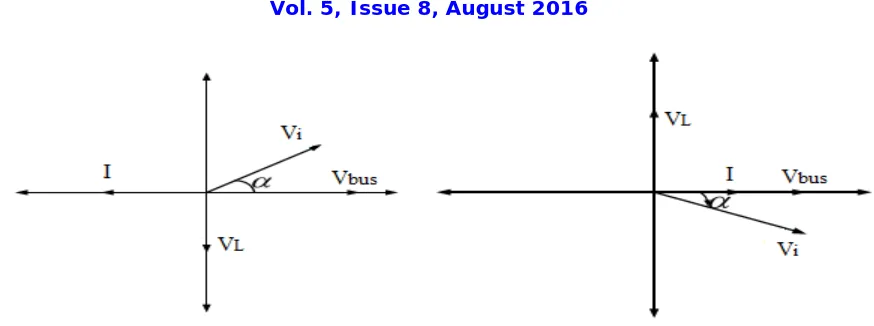
The operation of the DSTATCOM depends upon reactive current generation; it monitors the load voltages and currents and determines the amount of compensation needed by distribution system. Here active power flow is controlled by the angle between the ac system and voltage source inverter voltages. The reactive power flow is controlled by the difference between the magnitudes of these voltages. There are three modes of operation in DSTATCOM for real or reactive power generation and absorption
Fig. 2 Normal mode operation
1) If the DSTATCOM output voltage and the AC system voltage amplitude are equal, the reactive current will be zero then the DSTATCOM does not generate or absorb reactive power.it is normal mode of operation
2) If the DSTATCOM output voltage amplitude is more than the amplitude of the AC system voltage, the current flows through the transformer reactance from the DSTATCOM to the AC system. Then the device generates reactive power .So it operates in Capacitive modeThe phase angle will be negative
3)If the DSTATCOM output voltage amplitude is less than that of the AC system, then the current flows from the AC system to the DSTATCOM.Then the device absorbs reactive power .So it operates in inductive mode. In this mode of operation current lags voltage by an angle of 90.The phase angle will be positive
The active and reactive power can be calculated as
ISSN (Print) : 2320 – 3765 ISSN (Online): 2278 – 8875
I
nternational
J
ournal of
A
dvanced
R
esearch in
E
lectrical,
E
lectronics and
I
nstrumentation
E
ngineering
(An ISO 3297: 2007 Certified Organization)
Vol. 5, Issue 8, August 2016
Fig. 4 Active power mode(a)Inductive mode (b)Capaciive mode
The control algorithms of a DSTATCOM are implemented as follows.Measurements of system voltages and current and Signal conditioning Then calculate the compensating signal Then the firing pulses for the switching device is obtained. Generation of PWM signals is most important part of DSTATCOM control
III. PI AND HYSTERESIS CONTROL
Here we use PI controllers and a unit vector calculation method for the reference signal generation and a carrier less based hysteresis current controller is used for generation of pulses. Figure 5 shows the control system used for DSTATCOM The unit vectors for the in-phase and the quadrature voltages are obtained from the supply voltage. The in-phase unit vectors are (Ua, Ub and Uc).They are computed by dividing the ac voltages by their amplitude .The quadrature unit vectors are (Wa, Wb and Wc). It isobtained from in phase vector set. Vt is compared with the desired voltage Vtr to regulate PCC terminal voltage. The error is processed by a PI controller. The output of the PI controller is (Ismq) This decides amplitude of the reactive current to be generated by the DSTATCOM.Multiplying (Wa, Wb and Wc) with Ismq yields the quadrature component of the reference current (Isaq* , Isbq*, Iscq* ).The dc bus voltage (Vdc) is compared with the dc reference voltage (Vdcr). The error voltage is processed by another PI controller. The output of the PI controller is (Ismd).This decides the amplitude of the active power component of the source current. Multiplying (Ua, Ub, Uc) with Ismd gives the in-phase component of the reference source currents (Isad*, Isbd*, and Iscd* ). The reference source currents (Isa, Isb and Isc) are obtained by adding the corresponding in phase and the quadrature components, then compares the reference source currents (Isad*, Isbd*, and Iscd*) with sensed source currents (Isabc) .This generates the firing pulses for IGBT
ISSN (Print) : 2320 – 3765 ISSN (Online): 2278 – 8875
I
nternational
J
ournal of
A
dvanced
R
esearch in
E
lectrical,
E
lectronics and
I
nstrumentation
E
ngineering
(An ISO 3297: 2007 Certified Organization)
Vol. 5, Issue 8, August 2016
Vt is calculated as
The in-phase unit vectors are calculated as
The quadrature unit vectors (wa, wb and wc), are derived as
Computation of In-Phase Components of Reference Supply Currents
The amplitude of in-phase component of reference supply currents is computed using PI controller over the average value of dc bus voltage of the DSTATCOM and its reference counterpart.
Ismd(n) = Ismd(n-1) + Kpd(Vdcer(n) - Vdcer(n-1)) + KidVdcer(n)
where vdcer(n) = Vdcr - Vdc(n) denotes the error in Vdc at the nth sampling instant. The in-phase magnitudes of reference currents (Isad٭ , Isbd٭, and Iscd٭_) are calculated as:
Isad٭= IsmdUa Isbd٭ = IsmdUb Iscd٭ = IsmdUc
Computation of Quadrature Components of Reference Supply Currents
The amplitude Ismq(n) of the quadrature component of the reference source current at nth instant, is derived as output of the PI controller for maintaining ac terminal voltage constant at the nth instant and can be expressed as
Ismq(n) = Ismq(n-1) + Kpq(Vter(n) - Vter(n-1)) + KiqVter(n) where Vter(n) = Vtr - Vtm(n) denotes the error in Vtm calculated over reference
Vtr and average value of Vtm at nth sampling instant
Kpq and Kiq are the propor-tional and integral gains of the PI controller. The magnitude of quadrature components of the reference source currents are estimated as,
Isaq٭= IsmqWa
Isbq٭=IsmqWb Iscq٭ = IsmqWc
Total Reference Source Currents
The total reference source current is the sum of in-phase components and quadrature components
∗ = ∗ + ∗ ∗ = ∗ + ∗
ISSN (Print) : 2320 – 3765 ISSN (Online): 2278 – 8875
I
nternational
J
ournal of
A
dvanced
R
esearch in
E
lectrical,
E
lectronics and
I
nstrumentation
E
ngineering
(An ISO 3297: 2007 Certified Organization)
Vol. 5, Issue 8, August 2016
A PWM hysteresis controller is applied over the sensed (Isa, Isb, and Isc) and the reference values of supply currents (Isa٭, Isb٭, and Isc٭) to generate gating pulses for the IGBT switches
HYSTERESIS CURRENT CONTROLLER
Here the pulse is generated by Hysteresis PWM current controller generator in this project
The reference source currents (Isa٭, Isb٭ and Isc٭_) are compared with the sensed source currents (Isa, Isb, and Isc).The error in current is calculated as as,
Isaer = Isa ٭- Isa Isber = Isb ٭- Isb
Iscer = Isc ٭- Isc
The hysteresis controller adds a hysteresis band h (generally 1% to 5% of the current level) around the calculated reference current. When (Isa - Isa*) > +h, pulses are generated for the lower level switch S2 of phase 'a' leg. When (Isa - Isa*) < -h, pulses are generated for the upper level switch S1 of the phase 'a' leg of VSC. Similar principle is applied to phases b and c.
ISSN (Print) : 2320 – 3765 ISSN (Online): 2278 – 8875
I
nternational
J
ournal of
A
dvanced
R
esearch in
E
lectrical,
E
lectronics and
I
nstrumentation
E
ngineering
(An ISO 3297: 2007 Certified Organization)
Vol. 5, Issue 8, August 2016
IV. DESIGN REQUIREMENTS
The overall system consists of Test system, DSTATCOM and Control system. Here the test system contains three phase ac source, linear load and line reactance, The test system parameters and values are arranged in table For power factor correction linear RL load used and Qc kept as zero. The DSTATCOM is generally a voltage source inverter having 6 IGBT's which is connected to the ac line through the reactance of coupling transformer and filters. The design equations and selection of DC bus voltage, DC bus capacitor, AC inductor, ripple filter and VSC ratings are explained below
Parameter system values
Source voltage 415V
Frequeny,f 50Hz
Source resistance,Rs 0.001ohm
Source inductance,Ls 2mH
Linear load 56KW
Linear load ,QL 42Kvar
Non linear load,R,L 7ohm,100µH
DC BUS VOLTAGE
The minimum DC bus voltage must be maintained for effective operation of the DSTATCOM is ,
Where M is the modulation index considered 1 in this case and VLL is the line voltage considered 415V Thus Vdc is selected as 700 in this work.
DC BUS CAPACITOR
The DC bus capacitor should be large enough to limit the dc voltage ripples. The minimum value for Vdc is obtained as
,
Where Isc is the rated VSC current considered as 20A,.ω is the angular frequency i.e. 314rad/sec. Vdcer is ripple in capacitor voltage, and it is considered 2% of rated DC link voltage. The value of the capacitance is obtained as 22747.9 µF and chosen as 20000µF (for power factor correction),
AC INTERFACE INDUCTOR
AC interface inductor is connected between mid-point of each half bridge and PCC. The selection is based on permissible current ripple and can be obtained as
where M is the modulation index considered 1 in this case, a is overload factor considered 2 in this case, fs is switching frequency selected 20 kHz and Ifer is current ripple and it is considered 5%.
RIPPLE FILTER
ISSN (Print) : 2320 – 3765 ISSN (Online): 2278 – 8875
I
nternational
J
ournal of
A
dvanced
R
esearch in
E
lectrical,
E
lectronics and
I
nstrumentation
E
ngineering
(An ISO 3297: 2007 Certified Organization)
Vol. 5, Issue 8, August 2016
impedance at high frequency and high impedance at fundamental frequency. Which prevents the flow of fundamental components at fundamental frequency in the ripple filter branch and allows the Flow of high frequency noises through the ripple filter branch at higher than fundamental frequency
V. SIMULATION STUDIES
The modelling of test system, control system, and DSTATCOM have been done, and also the simulation of complete model in MATLAB/Simulink are developed .The simulation results and waveforms are included
MODELLING OF THE SYSTEM
The modelling of system includes, modelling of test system, DSTAT-COM and control system. In this paper a PI, unit vector calculation and Hysteresis controllers are used as the controllers.
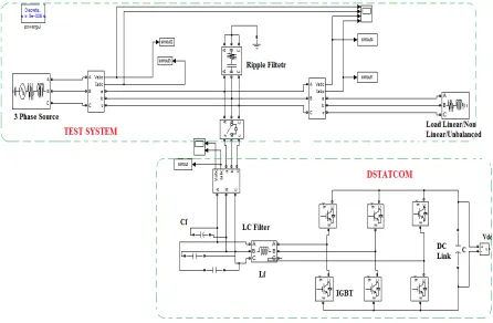
MODELLING OF TEST SYSTEM AND DSTATCOM
Figure shows the test system implemented in MATLAB/Simulink software to carry out the simulations for DSTATCOM.. Test system occurs at 415V three phase ac source, ripple filter, L-C filter, linear RL load and a resistive load with breaker (initially opened/closed condition and closed/open from 0.03 sec to 0.6 sec) as a sudden load application .For the power factor correction mode, no additional resistive loads are used. The L-C filter common but the ripple filter is used only when the ripple or noise is occurred at the injected waveform. DSTATCOM contains a three phase Voltage Source Inverter having 6 IGBT's and a dc link capacitor of 700V. VSC is connected to the ac system through the reactance of coupling transformer, this reactance with a delta connected capacitor bank act as a filter device. Here the DSTATCOM is connected to the system through a breaker (operating time of 0.3 sec to 0.6 sec). In power factor correction mode the breaker is removed.
ISSN (Print) : 2320 – 3765 ISSN (Online): 2278 – 8875
I
nternational
J
ournal of
A
dvanced
R
esearch in
E
lectrical,
E
lectronics and
I
nstrumentation
E
ngineering
(An ISO 3297: 2007 Certified Organization)
Vol. 5, Issue 8, August 2016
Fig.8: Simulink Model of Control System for Reference Current Signal Generation
ISSN (Print) : 2320 – 3765 ISSN (Online): 2278 – 8875
I
nternational
J
ournal of
A
dvanced
R
esearch in
E
lectrical,
E
lectronics and
I
nstrumentation
E
ngineering
(An ISO 3297: 2007 Certified Organization)
Vol. 5, Issue 8, August 2016
Fig.10 Simulink model of complete system
POWER FACTOR CORRECTION MODE
The power factor problems are mainly due to the unbalance in voltage and current waveforms and harmonics. In this work, phase 'a' of a linear R-L load is suddenly switched off for a duration of 0.15 to 0.3 seconds to create the reduced or low power factor by unbalance in load current and source current. A breaker with time sequence 0.15 to 0.3 sec is used to switch off the load. The figure shows the unbalance in load current and source
current, for a duration of 0.15 to 0.3 sec phase 'a' of load and source current is zero which create a reduced power factor of 0.7117 at source and load side. The aim is to improve the source side power factor near to unity.
DSTATCOM COMPENSATION
ISSN (Print) : 2320 – 3765 ISSN (Online): 2278 – 8875
I
nternational
J
ournal of
A
dvanced
R
esearch in
E
lectrical,
E
lectronics and
I
nstrumentation
E
ngineering
(An ISO 3297: 2007 Certified Organization)
Vol. 5, Issue 8, August 2016
Fig.10: Waveforms of (a) source voltage (b) source current (c)load voltage (d) load
current without any compensation
ISSN (Print) : 2320 – 3765 ISSN (Online): 2278 – 8875
I
nternational
J
ournal of
A
dvanced
R
esearch in
E
lectrical,
E
lectronics and
I
nstrumentation
E
ngineering
(An ISO 3297: 2007 Certified Organization)
Vol. 5, Issue 8, August 2016
Fig.12: Waveform of (a) DC-link voltage (b) Injected current (c) Reference current
VI. CONCLUSION AND FUTURE SCOPE
Voltage Source Inverter based Distribution Static Compensator with PI controller was modelled and simulated in MATLAB/SIMULINK. The respective results analyzed. The performance of the device has been tested with simulations at 415V voltage level The DSTATCOM with PI control system is connected through out to the system, to compensate the reduced power factor of 0.7117 at the source side to 0.939 by balancing the source current. For validation of its utility in real life situation; it needs the implementation under actual working conditions. The hardware implementation can be done with the help of DSP or Micro-controller. By incorporating Fuzzy logic instead of PI controllers the stability and performance can be improved
REFERENCES
[1]. T.Devaraju, Research Scholar, JNTU College of Engineering, Anantapur “Role of custom power devices in Power Quality Enhancement: A Review" International Journal of Engineering Science and Technology,2(8) pp.3628-3634, 2010
[2]. Satyaveer Gupt, Ankit Dixit, "Custom Power Devices For Power QualityImprovement:Review",International Journal of Research in Engineering and Applied Sciences, 2(2) (February 2012),1646-1659, 2012.
[3]. Power Quality Hand Book,Southern California Edison,Power Quality Department-7951, Redwood Avenue, Fontana.
[4]. Pragti Jyotishi, Proff. Deeparamchandani,”Mitigate Voltage Sag/Swell Condition and Power Quality Improvement in Distribution Line Using D-STATCOM"Pragti Jyotishi et al Int. Journal of Engineering Research and Applications, 3(6),pp.667-674, Nov-Dec 2013.
[5]. Raneru Nageswara Rao,”Harmonic Analysis of Small Scale Industrial Loads and Harmonic Mitigation Techniques in Industrial Distribution System", International Journal of Engineering Research and Applications, 3(4), pp.1511-1540, Jul-Aug 2013.
ISSN (Print) : 2320 – 3765 ISSN (Online): 2278 – 8875
I
nternational
J
ournal of
A
dvanced
R
esearch in
E
lectrical,
E
lectronics and
I
nstrumentation
E
ngineering
(An ISO 3297: 2007 Certified Organization)
Vol. 5, Issue 8, August 2016
[7]. Ambarnath Banerji, Sujit K. Biswas, Bhim Singh, “DSTATCOM Control Algorithms: A Review", International Journal of Power Electronics and Drive System, 2(3), September 2012, pp. 285-296.
[8]. Lakhinana Dinesh,Harish Sesham, “ Simulation of D-Statcom with Hysteresis Current Controller for Harmonic Reduction", IEEE,International Conference on Emerging Trends in Electrical Engineering and Energy Management 2012,Pp.104-108, April 2012.
[9]. Firas Marwan Flaih1, Jyoti Shrivastava, “DSTATCOM with LCL Filter to Im prove Voltage Sags and Current Harmonics in Power Distribution System " International Journal of Modern Engineering Research (IJMER),3(6), pp.3521-3528, Nov - Dec. 2013
[10].Donghua Chen, Shaojun Xie, "Review of the control strategies applied to active power filters", 2004 IEEE International Conference on Electric Utility Deregulation, Restructuring and Power Technologies, 0-7803-8237,pp.666-670, April 2004
[11].T. Narongrit, K-L. Areerak, “The Comparison Study of Current Control Tec niques for Active Power Filters", World Academy of Science, Engineering and Technology, 5, pp.344-349, December 2011
[12].Jianning Yang, Jiajun Guan, “A Novel Adaptive Harmonic Detecting Algorithm Applied To Active Power Filters", IEEE, 2010 3rd International Congress on Image and Signal Processing, pp.3287-3290, March 2010.