Vol. 4, Issue 10, October 2015
Arithmetic- Binary-2-RNS Converter Modulo
{2
n
±
k
} for
jn
-Bit Dynamic Range
T.K.Harika, V.prasad
M.Tech Student [VLSI], Department of ECE, Shree Institute of Technology, Tirupathi, India
Assistant Professor, Department of ECE, Shree Institute of Technology, Tirupathi, India
ABSTRACT: In this brief, a read-only-memoryless structure for binary-to-residue number system (RNS) conversion modulo {2n±k} is proposed. This structure is based only on adders and constant multipliers. This brief is motivated by the existing {2n± k} binary-2-RNS converters, which are particular inefficient for larger values of n. The experimental results obtained for 4n and 8n bits of dynamic range suggest that the proposed conversion structures are able to significantly improve the forward conversion efficiency, with an AT metric improvement above 100%, regarding the related state of the art. Delay improvements of 2.17 times with only 5%area increase can be achieved if a proper selection of the {2n± k} moduli is performed.
KEYWORDS: Arithmetic, binary-2-RNS, forward conversion, residue number systems.
I. INTRODUCTION
Residue number system (RNS) is a nonweighted numbering system, which uses remainders to represent numbers. Its modular characteristics offer the potential for high-speed and parallel processing based on carry-free arithmetic [1]. The basic arithmetic operations (add, subtract, and multiply) are independently implemented over multiple channels, defined by the moduli set that supports each particular RNS. The RNS moduli set is set up by defining the moduli, where mi represents positive relatively prime integers. A number X is represented in RNS by its residues xi = (X)mi, where xi is the remainder of the division of X by mi . Conversion from weighted number system to RNS (binary to-RNS or forward conversion), and vice versa (RNS-to-binary or reverse conversion), is required in order to implement a complete RNS-based processing system. Subsequently, RNS is usually used on computational intensive applications, such as digital signal processing, filtering, convolution, correlation, fast Fourier transform computation, and cryptography [2]–[4]. Initially, research on
RNS was mainly focused on the three modulus set {2n− 1, 2n, 2n+ 1} [5]. More recently, different RNS moduli sets have been proposed in order to increase the dynamic range (DR) and/or reduce the width of the RNS channels, such as {2n−3,
2nn−1, 2n+1, 2n+3} in [6] and [7], {2n−1, 2n+β , 2n+1} in [8], {2n− 1, 2n, 2n+ 1, 2n+1 − 1} in [9], and {2n− 1, 2n,2n+ 1, 22n+ 1} in [10]. More recently, the moduli set with a DR up to (8n
+ 1) bits have been proposed. This set [11] is composed by the moduli {2n+β , 2n−1, 2n+1, 2n− 2 + 1, 2n+ 2 + 1, 2n+1 + 1}, requiring
arithmetic units modulo {2n±1}[12], and generic arithmetic units modulo {2n±k}[13] for the modulo{2n− 2 + 1, 2n+ 2 + 1} channels. The use of the moduli {2n± k} with unrestricted k values, is rather useful to obtain larger RNS moduli sets [4], resulting in circuits with improved metrics. With larger moduli sets for the same DR, the operands are smaller, and consequently more compact arithmetic units are achieved, with reduced delay and circuit area requirements. However, most of the forward converters presented in the state of the art [14]–[19] are limited in terms of the number of bits per channel, or are unable to scale for larger DR, given their exponential growth with the number of bits per channel, mostly having structures based on lookup tables, such as read only memories (ROMs).
The structures proposed in [15] are based on weighted reduction, considering a serial, serial–parallel, or fully parallel approaches. An optimized version of these structures, considering the periodicity property, was proposed in [16]. However, the periodicity property can only be used to improve the conversion when shorter period values for modulo {2n ± k} can be found. More recently, a novel conversion structure has been proposed in [17] that overcome this dependency using the distributive property instead of periodicity, allowing for unrestricted modulo values. In [18], multimoduli architectures are proposed, using a weight selection algorithm, with binary additions and ROMs. These architectures allow performing the same arithmetic operations for different moduli within the same structure, but suffer from the same lack of scalability for larger DR. Furthermore, since the brief herein presented is focused on simple single-modulo conversion structures, these are not herein considered. In [19], the analysis and implementation of a computer-aided design (CAD) tool is presented, capable of generating a structural description of binary-to- RNS converters, for a DR up to 21 bits. The proposed method actually allows achieving forward converters for any DR, as herein shown.
Vol. 4, Issue 10, October 2015
[14] proposed in the related state of the art. To evaluate the performance of the proposed structure, the experimental results were obtained. These results
suggest that the proposed forward conversion topology allows improvements of 85% in area and 15% in delay when compared with the ROM-based modulo {2n ± k} binary-2-RNS converters proposed in [14]. Moreover, improvements up to 50% on delay can be achieved when comparing with the ROM-less-based converters proposed in [19], with a minimal increase in circuit area resources, 10% higher on average.
This brief is organized as follows. Section II introduces the formulation adopted to design the modulo {2n±k} binary-2-RNS conversion structure described in Section III. Section IV presents the experimental results, and compares the proposed topology with the related state of the art. The conclusion is presented in Section V.
II. FORMULATION OF RNS CONVERSION MODULO {2n ± k}
Consider a integer X with m-bit inputs, herein represented as {X [m-1],…, X [1], X[0]} with X = .x[i], a forward converter for modulo {2n ± k} transforms X into a residue value r with wmod bits, {r[wmod-1] ,…,r[1], r[0]}, with wmod =[log2 (2n ± k)] ; wmod = n for modulo {2n-k} and wmod = n+1 for modulo {2n+k}, when 0 < k < 2n. The residue modulo {2n ± k} of the input value X can be achieved by computing the integer division of X by 2n ± k, but it is a costly operation to obtain the remainder.
The approach herein considered to derive (X) 2n ± k is based solely on simple modular arithmetic operations, given the propriety
(2n) 2n ± k = (2n ± k k) 2n ± k = ( k) 2n ± k……….(1)
and with Xv X[(v+1). n-1:v.n], and considering X as the binary representation of an integer to be converted, with a DR of jn bits, where X[msb:lsb] represents the msb to lsb bits of integer X. The residue modulo {2n-k} of the value X with jn bits can be computed as
(X) 2n - k = (2(j-1)nX[jn-1:(j-1)n+…+22n X[3n-1:2n] + 2n X[2n-1:n] + X[n-1:01]) 2n – k
=(2(j-1)nXj-1 +…+ (2n-k+k) (2n-k+k) X2 +(2n-k+k) X1 + X0) 2n – k
=(kj-1Xj-1 +…+ k2x2+kx1+x0) 2n – k
=( ) 2n – k………...(2)
Identically, the residue modulo {2n+k} of X can be computed as
(X) 2n + k = (-kj-1Xj-1 +…+ k2X2 –kX1+X0) 2n + k
= ( k2ix2i - ( k2i+1x2i+1) 2n + k ………...(3)
The modular subtraction in (3) can be computed as
(-Xl) 2n + k = (2n =1-xl +k+1) 2n + k
+ ( l+ k +1) 2n + k ...(4) Given (4), (3) can be rewritten as
(X) 2n + k = ( k2ix2i + ( k2i+1( 2i+1+k+1)) 2n + k
= ( k2ix2i + ( k2i+1 2i+1
+ k2i+1 (k+1) 2n + k ………(5)
Where
( k2i+1 (k+1) 2n + k) Is a constant (cst).
III. HARDWARE STRUCTURES
To the best of the author’s knowledge, the existing generic modulo {2n
± k} binary-2-RNS converters are based on the weight-selection approach [14]-[19].
In the first approach proposed in [14], each n-bit segment of the binary input value is passed through a lookup table, outputting the corresponding residue value. Each table has an n-bit input and an n-bit output. The outputs of these lookup tables are then added by an adder-tree structure and further reduced modulo by an additional lookup table and a final {2n ± k} modulo adder. This conversion structure is herein referred as Piestrak [14]. Given the exponentially area increases of the lookup tables, implemented by ROMs, this structure is only efficient for small values of n. In [15], a conversion
Vol. 4, Issue 10, October 2015
structure considering weight selection based only on multiplexers and modular adders is proposed, herein referred to as Premkumar. The same author
extend his work in [16] using the periodicity property, which can also be employed in the remaining state of the art. However, this technique can only be used to improve the conversion when shorter period values for modulo {2n ± k} can be found. More recently, a new converter was proposed in [17], allowing the best conversion implementations for DR up to 64 bits with modulo up to 6 bits. This architecture is based on a depth-bounded carry-save addition, with a carry-free reduction of the sum and carry vectors. The final reduction is accomplished using a modified modulo adder and a lookup table. For larger moduli and DRs, the usage of the lookup table makes it once more not scalable. In [20], another weight selection-based conversion approach is proposed. However, in this case, the resulting structure is based solely on full adders, allowing it to scale to larger moduli channels and DRs. The authors also made available a CAD tool to facilitate the implementation of the proposed conversion structures [19]. However, the developed tool only considers DR up to 21 bits. In order to obtain conversion structures for the considered DRs, an augmented version of this CAD tool was developed, considering the proposed method [20]. The version implemented by us now allows for the unrestricted DR, and was designed to use the same optimized arithmetic structures used in the herein proposed conversion structures. The conversions structures generated by the new tool are herein referred as Soudris.
Given the inadequacy of most of the related state-of-the-art structures, for larger values of n, two new generic binary-2-RNS conversion structures are herein proposed for modulo {2n ± k},only requiring arithmetic operations. These conversion units only require constant multiplication and addition units: 1) Proposed I structure targets a more compact structure with a serialized modular reduction approach, which is an extension of the previous work presented in [21], but allowing now to compute X modulo {2n ± k} with DR of jn bits instead of the previous 4n bits; 2) Proposed II structure targets faster conversion considering a parallel approach. In these proposed structures, a restriction to the width of k (wk) is considered, allowing to simplifying the modular reduction step, namely wk≡ [log2 k] ≤ n/2. Even with this restriction of wk, the kiconstant value in (2) and (3) can be greater than 2n ± k for i ≥ 2, since for k < 2n/2 results in ki< 2n.i/2. In these cases, the resulting modulo constant (ki) 2n ± k can be precomputed and reduced modulo {2n ± k} providing a constant value with wki bits, where wki= [log2((ki) 2n ± k)] The maximum width of k values is represented by wkmax = max(wki), ∀ 0 ≤ i ≤ j − 1.
Proposed II structure for modulo {2n ± k} forward conversion is based on a parallel approach. In this approach, each partial operation (ki・Xi ) is first reduced modulo {2n ± k} and only then added to obtain the final residue value. Thus, computation is performed in two stages: the first stage computes the constant multiplication vectors and the second stage performs the addition of all those vectors. This structure performs the modular reduction of each calculation, using the modulo {2n ± k} Carry-Save-Adder [22], instead of adding all terms and reducing then iteratively at the end, as in Proposed I.
The considered modular kiconstant multiplication block computes ((ki) {2n ± k} xi) 2n ± k as
((ki) 2n ± k. xi) 2n ± k =(ki[wki-1:0]. X [(i+1).n-1:i.n]) 2n ± k
= (P1
[n+wki-1:0]) 2n ± k
= (2n. P1[n+wki-1:n]) + P1[n-1:0]) 2n ± k
= ( k. P1[n+wki-1:n]) + P1[n-1:0]) 2n ± k
= (P2[wkiwk-1:0]) + P1[n-1:0]) 2n ± k ………...(6)
Vol. 4, Issue 10, October 2015
((ki) 2n ± k. xi) 2n ± k
= ( k. P2[wki+wk-1::n]) + P2[n-1:0]) 2n ± k
= (P3[wki+2wk-n-1:0]) + P2[n-1:0]) + p1[n-1:0])2n ± k…………..(7)
Therefore, the kiconstant modular multiplication can be implemented with two constant multipliers when (w
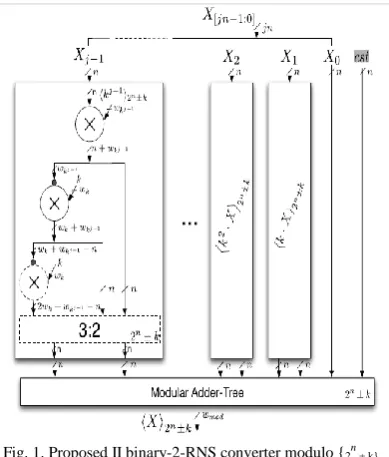
ki+wk ) ≤ n, or with an additional constant multiplier and a 3:2 modular compressor [22], when (wki+wk ) > n. The resulting modular k iconstant multiplication block is shown in Fig. 1. The additional resources for the more complex implementation case are represented with dashed lines. After the computation of ((ki) 2n ± k. xi) 2n
± k, the resulting carry-and save vectors are feed into a modular adder tree to obtain the final result (X) 2n ± k. In the particular case of the binary-2-RNS modulo {2n+k}, an additional input is required in the modular adder tree to compute the addition of the correction factor cst, from (6).
IV. EXPERIMENTAL RESULTS
In order to fully evaluate the proposed binary-2-RNS converters and the related state of the art, all structures were described in Very High Speed Integrate Circuits Hardware Description Language and mapped to an application-specified integrated circuit technology, in particular for the United Microelectronics Corporation (UMC) 0.13-μm CMOS technology from UMC [23]. The ROM results have been obtained by synthesizing the available ROM sizes in the synchronous via-1 ROM compiler for the UMC 0.13-μm high-speed logic process technology, and the others were estimated based on the real obtained values. Both synthesis and mapping results were performed using Design Vision E-2010.12-SP4 from Synopsys.
In order to take into account the impact of different values for n and k, the presented experimental results were obtained for a variation of n ∈ [6, 32]. For the value k, the best case is obtained for k = 3, and for the worst case, the values k = 2n/2−1 and ((ki) 2n ± k= 2n−1 are considered. The worst case value for k correspond to the worst case scenario for Proposed I and Proposed II structures implying the most complex and costly multipliers. Since for the Soudris structure the worst case scenario cannot be easily determined, and to simplify the analysis, the same value of k, k = 2n/2 −1, is used as the worst case value. For the Premkumar structure, the presented values are for k = 3, since no significant variations occur for other values of k. In order to properly evaluate the cost of the several conversion structures, RNS with four and eight moduli channels are considered, resulting in a DR of 4n and 8n, respectively. The obtained experimental results for circuit area and delay are shown in Fig. 2(a), (b), (d), and (e).
Vol. 4, Issue 10, October 2015
Fig. 2. Experimental results for binary-2-RNS converter with areas. (a) DR 4n - modulo 2n ± k (b) DR 8n - modulo 2n ± k and (c) j = 4, n = 20, varying k and delays, (d) DR 4n - modulo 2n ± k (e) DR 8n - modulo 2n ± k and (f) j = 4, n = 20, varying k.
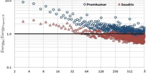
Fig. 3. Ratio of the energy consumption for j = 4, n = 20, varying k.
multipliers are in the most complex form. Still, less area demanding conversion units can be obtained with the proposed conversion structures, when compared with the related state of the art, in particular for larger values of n. Given the parallel approach of Proposed II structure, when compared with Proposed I, slightly higher area requirements are observed. From the obtained area results, it can also be concluded that the area increases with the number of moduli channels ( j ), since more constant multipliers and adders are needed, in particular for the more parallel Proposed II structure. The obtained experimental results suggest that the ROM-based related art (Piestrak) can in fact be faster, but only for values of n up to 18 bits. The modular adder-based conversion structure from Premkumar has worst delay metric than Piestrak for n up to 18 bits, but achieves better delay metrics for n greater than 20 bits. The Soudris conversion structure has the worst delay for the considered structures, nevertheless for n greater than 22 bits better delay metrics than the Piestrak conversion structure can be achieved. Regarding the proposed conversion structures, Proposed II conversion structure is able to achieve lower delay metrics than the related state of the art for n as low as 8 bits. Proposed II structure is always faster for n greater than 18 bits, even for the worst case of k, for acceptable area costs. The delay improvement inversion point depends on the number of modulo channels (j) and the considered k values. For example, the Premkumar converter allows to achieve better delay metric regarding ours in the worst cases. However, requiring on average 5.42 times more area resources. On average, the obtained results, for k = 3 and for the worst value of k, suggest that Proposed I structure requires on average 91%–87% less area, and is on average 10% faster to 16% slower than the Piestrak and Premkumar conversion structures, respectively. Regarding the Soudris structure, it allows for a 12% faster conversion at a cost of 44% more area resources. The experimental results suggest that Proposed II structure is on average 85%–80% smaller and 30%–5% faster than the Piestrak and the Premkumar structures, respectively. When compared with the Soudris structure, the experimental results suggest that Proposed II structure is on average 40% faster at a cost of 56% more circuit area. Note that this average is obtained from k = 3 and k = worst case, which does not allow to fully interpret the resulting metrics. To better understand the variation of these metrics with the variation of the k value, the Premkumar, the Soudris, and Proposed II conversion structures were synthesized for all possible k values for n = 20, considering a DR of 4n bits and modulo {2n− k}, as shown in Fig. 2(c) and (f). From these results, it can be seen that the Premkumar structure has a stable value for the delay metric, meaning that the obtained results are less dependent of the values of k. However, this invariance is achieved at significantly higher area costs, up to 18 times more area resources than Proposed II, being outside of the considered scale in Fig. 2(c). The obtained results also suggest that Proposed II structure is always faster than Soudris, in particular for smaller values of k. For the first 100 k values, the structure herein proposed achieves an average delay improvement of 48% when compared with the Soudris structure, at a cost of 36% more area resources. If the best 16 k values of each structure are considered, the delay of Proposed II structure is on average 2.17 times faster with just 5% additional area resources, resulting in an AT performance metric improvement of 108%. When considering the energy consumption per conversion, Proposed II structure suggests the largest variation, according to the selected k value, as shown in Fig. 3. Nevertheless, the obtained results suggest that with an adequate selection of the moduli set, (i.e., the k values) significantly less energy is required for the conversion. For example, for a moduli set with four channels, the Soudris and the Premkumar structures require 128% and 594% more energy, respectively, than Proposed II structure, with a modulo conversion requiring an average of 110 nJ. The results also suggest that, if the moduli set are extended to 16 channels, the Soudris and the Premkumar structures will require 50% and 264% more energy than Proposed II structure, respectively. From this, it can be concluded that Proposed II conversion structure allows for significantly more efficient conversion metrics, in particular if the k values are adequately selected.
V. CONCLUSION
In this brief, two generic and scalable modulo {2n ± k} binary-2-RNS conversion structures are proposed for jn-bit DRs. The proposed approach splits the jn input bits into j input sets, and computes the respective residue value using modular additions and constant multiplications, implementing ROM-less structures. To assess the gains achieved by the proposed structures, the experimental results were obtained for 4n- and 8n-bit DRs. The obtained experimental results suggest that the proposed conversion approach allows for average delay improvements between 10% and 40%, with a worst average area cost between 44% and 56%, regarding the best existing state of the art. Nevertheless, if a proper selection of the used k values is performed, 2.17 times faster conversion operations with only 5% extra area resources can be achieved, with AT performance metric improvements above 100%.
Vol. 4, Issue 10, October 2015
1] N. Szabo and R. Tanaka, Residue Arithmetic and Its Applications to Computer Technology. New York, NY, USA: McGraw-Hill, 1967. [2] G. Cardarilli, A. Nannarelli, and M. Re, “Residue number system for low-power DSP applications,” in Proc. 41st ACSSC, 2007, pp. 1412–1416. [3] J. Bajard and L. Imbert, “A full RNS implementation of RSA,” IEEE Trans. Comput., vol. 53, no. 6, pp. 769–774, Jun. 2004.
[4] S. Antão, J.-C. Bajard, and L. Sousa, “RNS based elliptic curve point multiplication for massive parallel architectures,” Comput. J., vol. 55, no. 5, pp. 629–647, 2011.
[5] F. E. P. D. Gallaher and P. Srinivasan, “The digit paralell method for fast RNS to weighted number system conversion for specific moduli {2n−1 , 2n, 2n+1},” IEEE Trans. Circuits Syst. II, Analog Digit. Signal Process., vol. 44, no. 1, pp. 53–57, Jan. 1997.
[6] P. A. Mohan, “Reverse converters for the moduli sets {22N− 1, 2N, 22N+ 1} and {2N− 3, 2N+ 1, 2N− 1, 2N+ 3},” in Proc. SPCOM, Dec. 2004, pp. 188–192.
[7] M.-H. Sheu, S.-H. Lin, C. Chen, and S.-W. Yang, “An efficient VLSI design for a residue to binary converter for general balance moduli {2n− 3, 2n + 1, 2n− 1, 2n+ 3},” IEEE Trans. Circuits Syst., Exp. Briefs, vol. 51, no. 3, pp. 152–155, Mar. 2004.
[8] R. Chaves and L. Sousa, “{2n+ 1, 2n+k , 2n− 1}: A new RNS moduli set extension,” in Proc. EUROMICRO Syst. Digit. Syst. Des., Sep. 2004, pp. 210–217.
[9] A. Premkumar and A. P. Vinod, “A memoryless reverse converter for the 4-moduli superset {2n− 1
, 2n, 2n+ 1, 2n+1 − 1},” J. Circuits, Syst. Comput., vol. 10, no. 2, pp. 85–99, 2000.
[10] B. Cao, C.-H. Chang, and T. Srikanthan, “An efficient reverse converter for the 4-moduli set {2n−1, 2n , 2n+1, 22n+1} based on the new Chinese remainder theorem,” IEEE Trans. Circuits Syst., Fundam. Theory Appl., vol. 50, no. 10, pp. 1296–1303, Oct. 2003.
[11] H. Pettenghi, R. Chaves, and L. Sousa, “RNS reverse converters for moduli sets with dynamic ranges up to (8n+1)-bit,” IEEE Trans. Circuits Syst., Reg. Papers, vol. 60, no. 6, pp. 1–14, May 2012.
[12] R. Zimmermann, “Efficient VLSI implementation of modulo {2n ± 1} addition and multiplication,” in Proc. 14th IEEE Symp. Comput. Arithmetic, Jun. 1999, pp. 158–167.
[13] P. Matutino, H. Pettenghi, R. Chaves, and L. Sousa, “RNS arithmetic units for modulo {2n ± k},” in Proc. 15th Euromicro Conf. DSD, Sep. 2012, pp. 795–802.
[14] S. Piestrak, “Design of residue generators and multi operand modular adders using carry-save adders,” IEEE Trans. Comput., vol. 43, no. 1, pp. 68–77, Jan. 1994.
[15] A. Premkumar, “A formal framework for conversion from binary to residue numbers,” IEEE Trans. Circuits Syst., Analog Digit. Signal Process., vol. 49, no. 2, pp. 135–144, Feb. 2002.
[16] A. Premkumar, E. Ang, and E.-K. Lai, “Improved memoryless RNS forward converter based on the periodicity of residues,” IEEE Trans. Circuits Syst., Exp. Briefs, vol. 53, no. 2, pp. 133–137, Feb. 2006.
[17] J. Low and C.-H. Chang, “A new approach to the design of efficient residue generators for arbitrary moduli,” IEEE Trans. Circuits Syst., Reg. Papers, vol. 60, no. 9, pp. 2366–2374, Aug. 2013.
[18] H. Pettenghi, L. Sousa, and J. Ambrose, “Efficient mplementation of multi-moduli architectures for binary-2-RNS conversion,” in Proc. 17th ASP-DAC Asia South Pacific, 2012, pp. 819–824.
[19] D. Soudris, M. Dasigenis, S. Vasilopoulou, and A. Thanailakis, “A CAD tool for architecture level exploration and automatic generation of RNS converters,” in Proc. IEEE ISCAS, vol. 4. May 2001, pp. 730–733.
[20] D. Soudris, M. Dasygenis, and A. Thanailakis, “VLSI methodology for the design of RNS and QRNS full adder based converters,” IEE Proc. Circuits, Devices Syst., vol. 149, no. 4, pp. 241–250,Aug. 2002.
[21] P. M. Matutino, H. Pettenghi, R. Chaves, and L. Sousa, “Multiplierbased binary-2-RNS converter modulo {2n
± k} in Proc. 26th Conf.DCIS, Nov. 2011, pp. 125–130.