ISSN 2348 – 7968
Reliability Enhancement Using Parity Algorithm
1
Gayathree.K, 2David.S, 3Moortheeswari.M
1
PG Student, Department of Electronics and Communication Engineering,
Sri Eshwar College of Engineering, Coimbatore, India
2
Assistant professor, Department of Electronics and Communication Engineering,
Sri Eshwar College of Engineering, Coimbatore, India
3
GET,Caliber Embedded Technologies,Coimbatore,India
ABSTRACT- The main issue in the field of data
storage is the possibility of error. To prevent this
several error correction algorithms are used. The
DMC utilizes decimal algorithm to obtain the
maximum error detection i.e detects more than two
bits of error compared with binary error correction
techniques. The power of DMC+HA (52mW) is less
compared to DMC+RCA (54mW) and DMC without
ERT(58mW). But the number of redundant bit used
is more in decimal matrix code. To overcome this ,the
proposed Parity Matrix Code(PMC) is used in which
the area ,power and number of redundant bit is
reduced compared to the above DMC architecture.
Keywords—Error correction codes (ECCs), Decimal
Algorithm (DA), Built In Current Sensors (BICS),
Decimal Matrix Code (DMC), Reed Muller Code
(RMC), Puntured Differnce Set Code (PDS),parity
matrix code(PMC).
I. INTRODUCTION
The CMOS technology scaling to nm, low cost, high
density, and high speed integrated circuits with low
supply voltage has increased the probability of fault
occurrence in the memories. This lead to the major
reliability concern especially increases SRAM memory
are triple modular redundancy and error correction codes
(ECCs).
Soft errors are the major issue in the reliability of
memories. Soft error will not damage the hardware; they
only damage the data that is being processed. If
detected, soft errors are corrected by rewriting corrected
data in the place of erroneous data. Highly reliable
system uses error correction approach, however in many
systems it is difficult to correct data,or even impossible
to detect error.To prevent soft errors from causing
corruption in the data stored error correction codes are
used such as matrix code, hamming etc. when ECC is
used ,data are encoded when written in the memory and
data are decoded when read from the memory. Thus the
encoding and decoding process possess a vital impact on
the memory access time and complexity.Some
applications of Error Correction Codes are Data storage,
Deep space telecommunications and Satellite
broadcasting etc.
The single error detection and double adjacent error
detection presented in [2], [3] achieves enhanced
detection by performing selective shortening and
reordering of the matrix. Interleaving technique has been
used to restrain MCUs [4], which rearrange cells in the
physical arrangement to separate the bits in the same
ISSN 2348 – 7968 tight coupling of hardware structures from both cells and
comparison circuit structures [5]. The brief note about
the role of binary algorithm in the field of error detection
is presented in [6].
Built-in current sensors (BICS) are proposed to
assist with single-error correction and double-error
detection codes to provide protection against MCUs is
presented in [7],but its error detection capability is less
and also the complexilty of encoding and decoding
process is high. Although single bit upset is a major
concern about memory reliability, multiple cell upsets
(MCUs) have become a seriousreliability concern in
some memory applications [8].
The modified triple error RMC presented in [9] ,
possess a decoding circuit results in power saving,
improved performance, less delay overhead. This
provides protection against any triple error. The use of
ECC will improve the reliability but however this also
increases the area overhead and access time. If no error
correcting codes are used then it will result in less
reliability and fault tolerance.
II. DECIMAL ALGORITHM
To increase the error detection capability, the
decimal algorithm is adapted, i.e in case of decimal
algorithm multiple bits of error in the word can be
detected. The power consumed will be reduced
compared with the other error detection process like
PDS, RMC, and BICS etc. The decimal algorithm as the
uses decimal algorithm involves decimal integer
addition and decimal integer subtraction. The encoder
that performs DA consists of adders and xor gates. The
redundant bits used in the DA classified into two,
namely the horizontal syndrome bits and the vertical
syndrome bits. The horizontal syndrome bits is
computed using decimal integer addition using adders,
in DA multi-bit adders is used to compute the horizontal
syndrome bits. The vertical syndrome bit is computed
using XOR operation of the information bits. These two
redundant bits is stored in the memory along with the
information bits.
A.Limitations of DMC
The drawback of the proposed Decimal Matrix Code
is the usage of more number of redundant bits, i.e. to
secure a 32- bit information it requires 36 redundant bits
namely 20 horizontal syndrome bit and 16 vertical
syndrome bits. Thus the only drawback is the increase in
bandwidth. To overcome this, the number of redundant
bits used must be reduced. This redundant bit reduction
should not affect the security of the data as well. To
achieve these criteria a new code called the Party Matrix
Code is used in which the number of redundant bit is
reduced, meanwhile the security is also maintained.
III. PARITY ALGORITHM
The new technique named Parity Matrix Code (PMC)
uses parity algorithm (matrix multiplication and matrix
addition) which is used to detect and correct multiple
errors with less number of redundant bits compared to
Decimal Matrix Codes (DMC). The PMC corrects
maximum number of errors in the memories compared
to DMC and also consumes less power and area than the
Decimal Matrix Code. Consider a 32 – bit word to
which the Parity Matrix Code is applied and verified
ISSN 2348 – 7968 Consider an n-bit information bit and similar to the
decimal matrix code the 32-bit information is divided
into k symbols of m bits each, i.e. if a 32-bit information
is consider then divide the word into 8 symbols of 4 bits
each. Then represent each data symbols in column
vectors. Represent each parity bit with a column vector
containing a 1 in the row corresponding to each data bit
included in the computation and a zero in all other rows.
Next create a generator matrix [G], by arranging the
column vectors into a l×m matrix such that the columns
are ordered to match their corresponding bits in a code
word. Arranging the columns in any other order will just
change the positions of bits in the code word. Finally the
data is encoded by multiplying it with the generator
matrix. This encoded data is stored in the memory. The
stored data/information may be corrupted when exposed
to harmful radiations like gamma rays, x-rays etc.
A parity check matrix [H] is constructed such that
row 1 contains 1s in the position of the first parity bit
and all of the data bits that are included in its parity
calculation. Row 2 contains 1s in the position of the
second parity bit and all of the data bits that are included
in its parity calculation. Row 3 contains 1s in the
position of the third parity bit and all of the data bits that
are included in its parity calculation and so on.
Multiplying the encoded data with the H will result in a
syndrome generation. There are two useful proprieties of
the syndrome. If the syndrome is all zeros, the encoded
data is error free. If the syndrome has a non-zero value,
flipping the encoded bit that is in the position of the
column in [H] that matches the syndrome will result in a
valid code word. Thus the errors are detected and
corrected using parity matrix code.
IV.RESULTS AND DISCUSSION
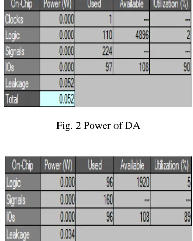
A.Power Analysis
The decimal matri consumes less power than the
existing codes like PDS, Built-In Current Sensor with
hamming code(BICS+HC),Built-In Current Sensor with
parity code(BICS+PR) etc. The low power of decimal
algorithm which is 52mW when compared with other
algorithms is shown in the Figure 2,
Fig. 2 Power of DA
Fig. 3 Power of PA
Fig. 3 shows the power consumption of PMC.It
also shows that the proposed Parity Matrix Code
consumes less power than the DMC and other existing
ISSN 2348 – 7968 code(BICS+HC),Built-In Current Sensor with parity
code(BICS+PR) etc.
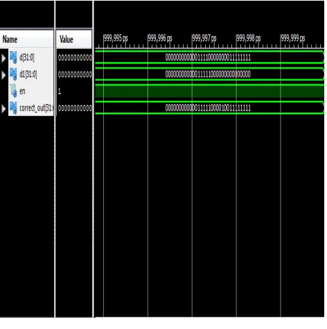
B. Simulation Results
The decimal algorithm is coded in vhdl and
simulated in Xilinx. The error detection capability of the
DA which is increased to 8 is shown in Figure 4,
Fig. 4 Simulation Output of DA
The simulation result of the proposed parity matrix
code is shown in Figure 5. The input is data_in, which is
a 32 bit information. The error_data is the corrupted
data that is forced as an error input. Finally the
corrected_data is the final error corrected valid output
obtained after performing the PMC operation.
Fig. 5 Simulation Output of DA
V. CONCLUSION
The Decimal Matrix Code uses decimal
addition/subtraction and ex-or operation to detect
and correct errors present in the memory. DMC
possess simple encoding and decoding architecture.
The decimal matrix code consumes less power than
the other existing codes. The DMC with RC adder
uses 54mW of power while the DMC with HA uses
only 52mW of power. The only drawback of DMC
is the more number of redundant bits i.e. 36, which
will increase the bandwidth utilization. The
reduction in the number of redundant bit will in turn
affect the reliability of the memory. So the
redundant bits must be reduced such that it will not
affect the reliability of the memory. The parity
matrix code is proposed to overcome the above
ISSN 2348 – 7968 matrix code reduces the number redundant bits to 24
but it also increases the error detection capability to
15. The power of PMC is 34mW which is 18mW
less than the decimal matrix codes.
REFERENCES
[1] Jing Guo and Liyi Xiao, “Enhanced Memory
Reliability Against Multiple Cell Upsets Using
Decimal Matrix Code,” IEEE Trans on Very Large
Scale Integration (VLSI) Systems, Vol. 22, No. 1,
January 2014.
[2] A. Sanchez-Macian, P. Reviriego, and J. A.
Maestro, “Hamming SEC-DAED and extended
hamming SEC-DED-TAED codes through selective
shortening and bit placement,” IEEE Trans. Device
Mater. Rel., Vol. 14, No.1, March 2014 .
[3] N. N. Mahatme, B. L. Bhuva, Y. P. Fang, and A. S.
Oates, “Impact of strained-Si PMOS transistors on
SRAM soft error rates,” IEEE Trans.Nucl. Sci., vol.
59, no. 4, pp. 845–850, Aug. 2012.
[4] S. Baeg, S. Wen, and R. Wong, “Interleaving
distance selection with a soft error failure model,”
IEEE Trans. Nucl. Sci., vol. 56, no. 4, pp. 2111–
2118, Aug. 2009.
[5] S. Baeg, S. Wen, and R. Wong, “Minimizing soft
errors in TCAM devices: A probabilistic approach to
determining scrubbing intervals,” IEEE Trans.
Circuits Syst. I, Reg. Papers, vol. 57, no. 4, pp. 814–
822, Apr. 2010.
[6] P. Reviriego and J. A. Maestro, “Efficient error
detection codes for multiple-bit upset correction in
SRAMs with BICS,” ACM Trans. Design Autom.
Electron. Syst., vol. 14, no. 1, pp. 18:1–18:10, Jan.
2009.
[7] C. Argyrides, R. Chipana, F. Vargas, and D. K.
Pradhan, “Reliability analysis of H-tree random
access memories implemented with built in current
sensors and parity codes for multiple bit upset
correction,” IEEE Trans. Rel., vol. 60, no. 3, pp.
528–537, Sep. 2011.
[8] E. Ibe, H. Taniguchi, Y. Yahagi, K. Shimbo, and T.
Toba, “Impact of scaling on neutron induced soft
error in SRAMs from an 250 nm to a 22 nm design
rule,” IEEE Trans. Electron Devices, vol. 57, no. 7,