Analysis and Automatic Reset of Three Phase
Faults
F. J. Sayyad1, S. L. Surve2, A. P. Talekar3, T. V. Deokar4
UG Student, Dept. of EE, SBPCOE Engineering College, Indapur, Maharashtra, India1
Assistant Professor, Dept. of EE, SBPCOE Engineering College, Indapur, Maharashtra, India2
ABSTRACT: In this paper we develop the fault tripping and automatic reset mechanism. Our main objective is to reset the temporary faults and permanent tripping for other fault cases. The electrical substation which supply the power to the consumers, have failures due to some faults which can be temporary or permanent. These faults lead to substantial damage to the power system equipment. In India it is common, The faults might be LG (Line to Ground), LL (Line to Line), 3L (Three lines) in the supply systems and these faults in three phase supply system can affect the power system. To overcome this problem a system is built, which can sense these faults and automatically disconnects the supply to avoid large scale damage to the control gears in the grid sub-stations. This system is built using three single phase transformers which are wired in star input and star output, and 3 transformers are connected in delta connections, having input 220 volt and output at 12 volt. This concept low voltage testing of fault conditions is followed as it is not advisable to create on mains line. 555 timers are used for handling short duration and long duration fault conditions. A set of switches are used to create the LL, LG and 3L fault in low voltage side, for activating the tripping mechanism. Short duration fault returns the supply to the load immediately called as temporary trip while long duration shall result in permanent trip.
KEYWORDS: Transformers, IC 555, Relays, LM 358, Transistors, Diodes, etc.
I.INTRODUCTION
Faults on transmission line can be caused by lightning strikes, l ash over on contaminated insulator surface, broken conducting line, short circuit between conducting lines, etc. Electromagnetic transients in power systems result from a variety of disturbances on transmission lines, such as faults, are extremely important. A fault occurs when two or more conductors come in contact with each other or ground in three Phase systems, faults are classified as Single line-to-ground faults, Line-to-line faults, Double line- to-line-to-ground faults, and three phase faults. For it is at such times that the power system components are subjected to the greatest stresses from excessive currents These faults give rise to serious damage on power system equipment. Fault which occurs on transmission lines not only ef f ects the equipment but also the power quality. There are 70 to 80 per. faults are LL, LL,LLG faults which is very dangerous faults for transmission line and line equipments. Other 30-20 per faults due to other environments i.e. lightning, trees etc. To provides better isolation for system automatic tripping mechanisms is used. For faulty period it cuts the power supply at load site and if the fault is temporary nature it will automatic recluse the power supply. In this way the power losses during faulty periods is saved and the system is now running in normal condition. We don’t need to go for restart in case of temporary fault condition.
II.COMPONENTS
Equipments used for this mechanisms: OP-AMP(LM358), IC 555, Transformers (230/12v), Relays, Relay driver, etc.We discuss here the use of this components in this mechanism.
for connecting and disconnecting the load from main supply. Also there is one scr is used for continuous supply after gate triggers.
IV.WORKING
Fig.1 Block diagram of fault reclosing mechanism
As shown in the figure 1. the two sets of step down transformers which arranged in star-star and star-delta combination which provides 12v supply to relay coils through fault switches. The primaries of 3 transformers are connected to a 3 phase supply in star configuration, while the secondary of the same is also connected in star configuration. The other set of 3 transformers with its primary connected in star to 3 phases have their secondaries connected in delta configuration. The outputs of all the 6 transformers are rectified and filtered individually and are given to 6 relay coils. Push buttons, one each connected across the relay coils to create LG & LL faults. There is total number of five relays are used, NO terminals connected in series (first relay NO to second relay Pole terminal connection) and pole is grounded. Output of last NO terminal of relay is connected to pin 2 of monostable ic 555 timer. It provides logic zero at fault condition. Output of monostable ic is provided to the reset pin 4 of Astable ic 555. During charging period it provides logic one, which say as fault exceed period. Pin 2 signal of Astable ic is provided to transistor gate terminal through resistor Rg. which gives voltage status across capacitor and triggers gate at particular voltage (2v/3). Anode terminal of transistor is connected at fix supply VCC and cathode o/p going relay driver coil, which complete the circuit. Also the o/p of pin 3 of Astable ic connected to non inverting terminal of OP-AMP, this is used for permanent fault conditions. Output of LM358 provides to relay driver. Relay controls the supply of load.
V.OPERATION
In this project we use the fault switches for creating the fault. Operation at different fault condition discussed below.
Astable IC is also zero. Here no activation of transistor due to voltage level at pin 2 is zero. Due to no output at non inverting terminal Op-amp not drive the relay.And no disturbance of power supply to load.
Temporary fault
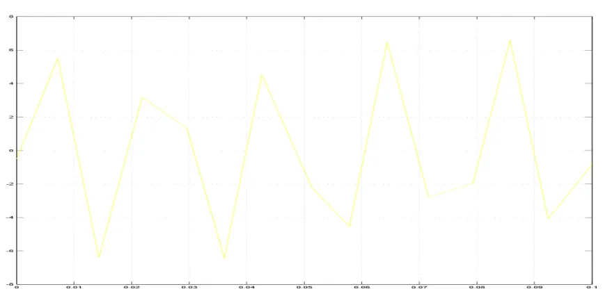
Figure 2. Temporary fault current & o/p current
For creating the temporary fault the switch is pushed for short duration, the fault period is tf shown in figure 2. Over the period of 'tf' NO terminal output is zero which causes to charging of capacitor c1(figure 1.) and output of monostable ic is high, this output for Astable ic causes to return from reset to active mode. Charging of capacitor C2 is starts (figure 1.) and output is high. As mentioned above the relay is drive by transistor, and load is disconnected from main supply. When switch is released (before charging of C2 at '2V/3' ) the output is low and supply is reconnected.
Permanent fault
Figure 3.Permanent fault current & o/p current
When the switch is closed for long duration as shown in figure 3 output goes low permanently. This is happening because transistor is triggered by Astable ic pin 2. At voltage across capacitor C2 (shown in figure 1.) is (2/3)Vcc gate current activate the transistor and transistor provides permanent supply to Op-amp. Due to this load is permanently disconnected.
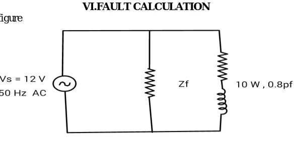
VI.FAULT CALCULATION
Considering following figure
Normal current,
I = 10/ (12*0.8) = 1.04 A For LG fault,
Fault current, at Zf = 2 ohm If = 12/2 = 6A
Figure 5.ll fault circuit For LL fault,
Considering following figure
Second voltage source lag by 120 degree of angle . V = V1 + V2(sin(120 + 36.87))
V = 12 + 12*(0.39282) V = 16.7138 V
Normal current = 10/ (0.8*16.7138) I = 0.7478 A
Fault current = 16.7138/2 If = 8.367 A
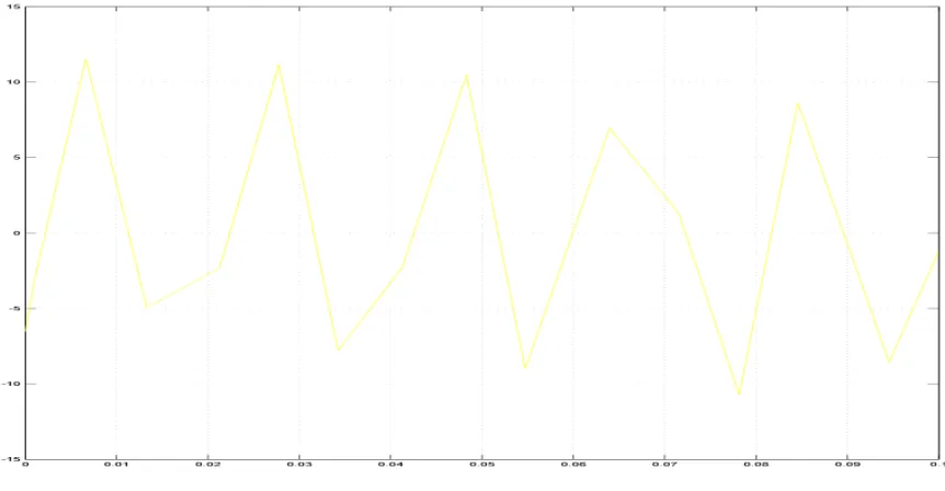
Simulation result: LG fault & LL fault
Figure 4.ll fault current by simulation
This result is helpful to use for designing of hardware module. So from that we analyse and design our hardware module, with following results:
Actuating time: nearly 10 msec Temporary fault period: nearly 5 sec Permanent fault period: 5 sec to infinity
VII.CONCLUSION
This project is to design the Hardware for to develop an automatic tripping mechanism for the three phase supply system while temporary fault and permanent fault occurs. Here we used 555 timers with relay for the analysis of fault is temporary or permanent. Short duration fault returns the supply to the load immediately called as temporary trip while long duration shall result in permanent trip. Also we adjust the time duration for permanent fault by adjusting capacitors charging periods.
REFERENCES
1. Sathish Bakanagari et al Int. Journal of Engineering Research and Applications (ISSN : 2248-9622, Vol. 3, Issue 6, Nov-Dec 2013, pp.1082-1086). 2. International Journal for scientific research & Development\ Vol. 3, Issue 01, 2015 \ ISSN (online): 2321-0613,Auto Reset and Tripping Technique for Temporary and Permanent Fault Analysis.