Hardware Implementation of Fuzzy
Controller Based PFC Cuk Converter Fed
BLDC Motor Drive
V. Jayalakshmi, K. Sakthi Priya
Assistant Professor, Department of Electrical and Electronics Engineering, Bharath University, Chennai, Tamil Nadu, India
P.G. Scholar, Department of Electrical and Electronics Engineering, Bharath University, Chennai, Tamil Nadu, India
ABSTRACT: The use of permanent-magnet brushless dc motor (BLDC) in low-power appliances is increasing because of its features of high efficiency, wide speed range, and low maintenance. This project deals with a power factor correction (PFC) based Cuk converter fed brushless DC motor (BLDC) drive as a cost effective solution for low power applications. The speed of the BLDC motor is controlled by varying the Dc bus voltage of voltage source inverter(VSI) which uses a low frequency switching of VSI (electronic commutation of BLDC motor) for low switching losses. A diode bridge rectifier (DBR) followed by a Cuk converter working in discontinuous conduction mode(DCM)is used for control DC link voltage with unity power factor at AC mains. The fuzzy based controller system is used for general purpose industrial applications. Performance of the PFC Cuk converter is evaluated in four different operation condition of discontinuous and continuous conduction mode (CCM) and a comparison is made to select a best suited mode of operation. Keywords: Converter, BLDC Motor, Fuzzy Controller, Matlab.
1. INTRODUCTION
(DTC) BLDC motor drive. They have the disadvantages of using a complex control which requires large amount of sensors and higher end digital signal processor (DSP) for attaining a DTC operation with PFC at AC mains. Hence, this scheme is not suited for low cost applications. Ho have proposed an active power factor correction (APFC) scheme which uses a PWM switching of VSI and hence has high switching losses. Wu have proposed a cascaded buck-boost converter fed BLDC motor drive, which utilizes two switches for PFC operation. This offers high switching losses in the front end converter due to doubles witch and reduces the efficiency of overall system. [7-10]
Selection of operating mode of front end converter is a trade-off between the allowed stresses on PFC switch and cost of the overall system. Continuous conduction mode (CCM) and discontinuous conduction mode (DCM) are the two different modes of operation in which a front end converter is designed to operate. A voltage follower approach is one of the control techniques which is used for a PFC converter operating in DCM. This voltage follower technique requires a single voltage sensor for controlling the DC link voltage with a unity power factor. Therefore, voltage follower control has an advantage over a current multiplier control of requiring a single voltage sensor.[11] This makes the control of voltage follower a simple way to achieve PFC and DC link voltage control, but at the cost of high stress on PFC converter switch. On the other hand, the current multiplier approach offers low stresses on the PFC
switch, but requires three sensors for PFC and DC link voltage control. [12]
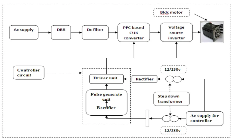
II. BLOCK DIAGRAM & EXPLANATION
Figure 1 Block diagram
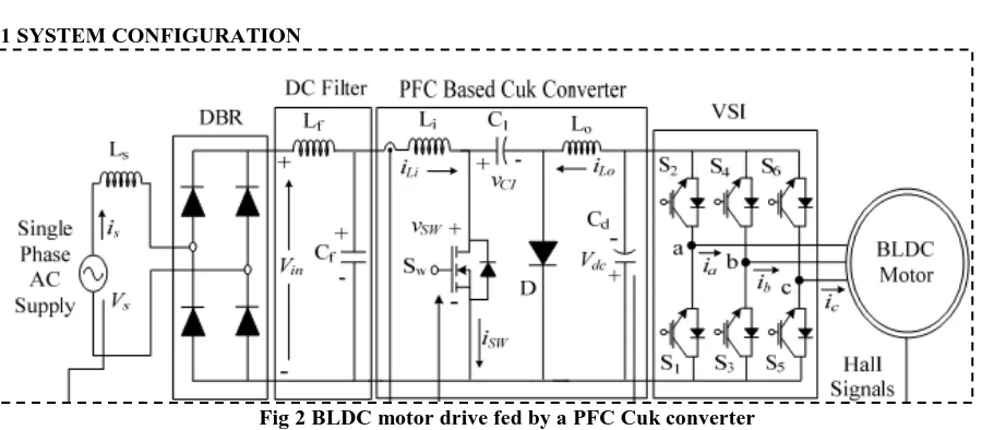
3.1 SYSTEM CONFIGURATION
Fig 2 BLDC motor drive fed by a PFC Cuk converter
Fig.2- shows the PFC Cuk converter based VSI fed BLDC motor drive using a current multiplier and a voltage follower approach respectively. [19]A high frequency metal oxide semiconductor field effect transistor (MOSFET) is used in Cuk converter for PFC and voltage control, whereas insulated gate bipolar transistor’s (IGBT) are used in the VSI for its low frequency operation.[20] BLDC motor is commutated electronically to operate the IGBT’s of VSI in fundamental frequency switching mode to reduce its switching losses. The PFC Cuk converter operating in CCM using a current multiplier approach is shown in Fig4.1; i.e. the current flowing in the input and output inductors (Li and Lo), and the voltage across the intermediate capacitor (C1) remain continuous in a switching period. The current flowing in either of the input or output inductor (Li and Lo) or the voltage across the intermediate capacitor (C1) become discontinuous in a switching period for a PFC Cuk converter operating in DCM. A Cuk converter is designed to operate in all three discontinuous conduction modes and a continuous conduction mode of operation and its performance is evaluated for a wide voltage control with unity power factor at AC mains.[21]
3.2 OPERATION OF CUK CONVERTER IN DIFFERENT MODES
The operation of Cuk converter is studied in four different modes of CCM and DCM. In CCM, the current in inductors (Li and Lo) and voltage across intermediate capacitor C1remain continuous in a switching period.[22-24] Moreover, the DCM operation is further classified into two broad categories of discontinuous inductor current mode (DICM) and discontinuous capacitor voltage mode (DCVM). In DICM, the current flowing in inductor Li or Lo becomes discontinuous in their respective modes of operation. While in DCVM operation, the voltage appearing across the intermediate capacitor C1 becomes discontinuous in a switching period. Different modes for operation of CCM and DCM are discussed as follows.[25]
CCM Operation
The operation of Cuk converter in CCM is described as follows. Figs.4. 2(a) and (b) show the operation of Cuk converter in two different intervals of a switching period and Fig.4.2(c) shows the associated waveforms in a complete switching period.[26-28]
Interval I: When switch Sw in turned on,inductor Li stores energy while capacitor C1 discharges and transfers its energy to DC link capacitor Cd as shown in Fig.4.2(a). [29]Input inductor current iLi increases while the voltage across
the intermediate capacitor VC1 decreases as shown in Fig4.2(c).[30]
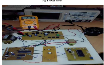
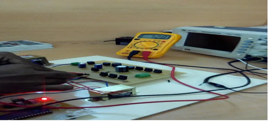
IV. HARDWARE IMPLEMENTATION
Fig. 4 Power circuit
Fig.5 Hardware setup.
-+
D1
W01G
2
1
3
4
TX1
V1
C1 470uF
U1
7805
1 3
VIN VOUT
C1 47uF
C1 0.1uF
R1
330
D2
LN211WP
1
2
JP1
1 2
1 2
230/9V
Fig 6 BLDC motor output.
Fig 7 BLDC motor output voltage waveform.
V. CONCLUSION
REFERENCES
[1] J. F. Gieras and M. Wing, Permanent Magnet Motor Technology-Design and Application, Marcel Dekker Inc., New York, 2002.
[2]Sukumaran V.G., Bharadwaj N., "Ceramics in dental applications", Trends in Biomaterials and Artificial Organs, ISSN : 0971-1198, 20(1) (2006) pp.7-11.
[3] C. L. Xia, Permanent Magnet Brushless DC Motor Drives and Controls,Wiley Press, Beijing, 2012.
[4] Selva Kumar S., Ram Krishna Rao M., Balasubramanian M.P., "Chemopreventive effects of Indigofera aspalathoides on 20-methylcholanthrene induced fibrosarcoma in rats", International Journal of Cancer Research, ISSN : ISSN: 1811-9727, 7(2) (2011) pp.144-151.
[5] Y. Chen, Y, C. Chiu, C, Y. Jhang, Z. Tang and R. Liang, “A Driver for the Single-Phase Brushless DC Fan Motor with Hybrid Winding Structure,” IEEE Trans. Ind. Electron., Early Access, 2012.
[6]Menon R., Kiran C.M., "Concomitant presentation of alopecia areata in siblings: A rare occurrence", International Journal of Trichology, ISSN : 0974-7753, 4(2) (2012) pp.86-88.
[7] S. Nikam, V. Rallabandi and B. Fernandes, “A high torque density permanent magnet free motor for in-wheel electric vehicle application,”IEEE
Trans. Ind. Appl., Early Access, 2012.
[8]Rayen R., Hariharan V.S., Elavazhagan N., Kamalendran N., Varadarajan R., "Dental management of hemophiliac child under general anesthesia", Journal of Indian Society of Pedodontics and Preventive Dentistry, ISSN : 0970-4388, 29(1) (2011) pp.74-79.
[9] X. Huang, A. Goodman, C. Gerada, Y. Fang and Q. Lu, “A SingleSided Matrix Converter Drive for a Brushless DC Motor in AerospaceApplications,” IEEE Trans. Ind. Electron., vol.59, no.9, pp.3542-3552,Sept. 2012.
[10]Shanthi B., Revathy C., Devi A.J.M., Subhashree, "Effect of iron deficiency on glycation of haemoglobin in nondiabetics", Journal of Clinical and Diagnostic Research, ISSN : 0973 - 709X, 7(1) (2013) pp.15-17.
[11] W. Cui, Y. Gong and M. H. Xu, “A Permanent Magnet Brushless DC Motor With Bifilar Winding for Automotive Engine Cooling Application,” IEEE Trans. Magnetics, vol.48, no.11, pp.3348-3351,Nov. 2012.
[12] C. C. Hwang, P. L. Li, C. T. Liu and C. Chen, C, “Design and analysis of a brushless DC motor for applications in robotics,” IET Elect.
Pow.Appl.,vol.6,no.7,pp.385-389,August 2012.
[13] T. K. A. Brekken, H. M. Hapke, C. Stillinger and J. Prudell, “Machines and Drives Comparison for Low-Power Renewable Energy and Oscillating Applications,” IEEE Trans. Energy Convers., vol.25, no.4,pp.1162-1170, Dec. 2010.
[14] N. Milivojevic, M. Krishnamurthy, A. Emadi and I. Stamenkovic, “Theory and Implementation of a Simple Digital Control Strategy for Brushless DC Generators," IEEE Trans. Power Electron., vol.26, no.11,pp.3345-3356, Nov. 2011
[15] T. Kenjo and S. Nagamori, Permanent Magnet Brushless DC Motors, Clarendon Press, Oxford, 1985.
[16] J. R. Handershot and T.J.E Miller, Design of Brushless Permanent Magnet Motors, Clarendon Press, Oxford, 2010. [17] T. J. Sokira and W. Jaffe, Brushless DC Motors: Electronic Commutation and Control, Tab Books, USA, 1989. [18] H. A. Toliyat and S. Campbell, DSP-based Electromechanical Motion Control, CRC Press, New York, 2004.
[19] Limits for Harmonic Current Emissions (Equipment input current ≤16 A per phase), International Standard IEC 61000-3-2, 2000. [20] N. Mohan, T. M. Undeland and W. P. Robbins, Power Electronics:
Converters, Applications and Design, John Wiley and Sons Inc, USA,2009.
[21] B. Singh, B. N. Singh, A. Chandra, K. Al-Haddad, A. Pandey and D.P.Kothari,“A review of single-phase improved power quality AC-DC converters,” IEEE Trans. Industrial Electron., vol. 50, no. 5, pp. 962–981, Oct.2003.
[22] B. Singh, S. Singh, A. Chandra and K. Al-Haddad, “Comprehensive Study of Single-Phase AC-DC Power Factor Corrected Converters With High-Frequency Isolation,” IEEE Trans. on Industrial Informatics,vol.7, no.4, pp.540-556, Nov. 2011.
[23] S. B. Ozturk, Oh Yang and H. A. Toliyat, “Power Factor Correction of Direct Torque Controlled Brushless DC Motor Drive,” 42nd IEEE IAS
Annual Meeting, pp.297-304, 23-27 Sept. 2007.
[24] T. Y. Ho, M. S. Chen, L. H. Yang and W. L. Lin, “The Design of a High
Power Factor Brushless DC Motor Drive,” 2012 Int. Symposium on Computer, Consumer and Control (IS3C), pp.345-348, 4-6 June 2012.
[25] C. H. Wu and Y. Y. Tzou, “Digital control strategy for efficiency optimization of a BLDC motor driver with VOPFC,” IEEE EnergyConversion
Congress and Exposition, (ECCE 2009), pp.2528-2534, 20-24 Sept. 2009.
[26] T. Gopalarathnam and H. A. Toliyat, “A new topology for unipolar brushless DC motor drive with high power factor,” IEEE Trans.
PowerElect., vol.18, no.6, pp. 1397-1404, Nov. 2003.
[27] V. Bist and B. Singh, “An Adjustable Speed PFC Bridgeless Buck-Boost
Converter Fed BLDC Motor Drive”, IEEE Trans. Ind. Electron., vol.61,no.6, pp.2665-2677, June 2014.
[28] B. Singh and V. Bist, “An Improved Power Quality Bridgeless Cuk Converter Fed BLDC Motor Drive for Air Conditioning System”, IETPower
Electron., vol. 6, no. 5, p. 902–913, 2013.
[29] B. Singh and V. Bist, “Power Quality Improvement in PFC Bridgeless SEPIC Fed BLDC Motor Drive”, Int. Jr. Emerging Electric Power
Sys.(IJEEPS). vol. 14, no. 3, Pages 285–296, 2013.
[30] V. Bist and B. Singh, “A Reduced Sensor PFC BL-Zeta Converter Based VSI Fed BLDC Motor Drive”, Electric Power System Research,vol. 98, pp. 11–18, May 2013.
[31] A. Ionovici, “A new computer-aided approach to the analysis of Cuk converter by using the alternator equations,” IEEE Trans. Power Electron., vol.4, no.3, pp.319-330, Jul 1989.
[32] S. C. Wong and Y. S. Lee, “SPICE modelling and simulation of hysteretic current-controlled Cuk converter,” IEEE Trans. Power Electron., vol.8, no.4, pp.580-587, Oct 1993.
[33] K. M. Smedley and S. Cuk, “Dynamics of one-cycle controlled Cuk converters,” IEEE Trans. Power Electron., vol. 10, no.6, pp.634-639,Nov 1995.
[34] L. Malesani, R. G. Spiazzi and P. Tenti, “Performance optimization ofCuk converters by sliding-mode control,” IEEE Trans. Power
Electron.,vol.10, no.3, pp.302-309, May 1995.
Research in Electrical, Electronics and Instrumentation Engineering, ISSN (Online): 2278 – 8875,pp 5596-5602, Vol. 2, Issue 11, November 2013 [37] P.Thamarai, B.Karthik, ARM Based Automatic Meteorological Data Acquisition System, International Journal of Advanced Research in Electrical, Electronics and Instrumentation Engineering, ISSN (Online): 2278 – 8875,pp 6461-6465, Vol. 2, Issue 12, December 2013
[38] M.Bharathi,Effective Transfer Function Approach for Decentralized Controller,International Journal of Advanced Research in Electrical, Electronics and Instrumentation Engineering, ISSN 2278 - 8875 , pp 21-27, Vol. 1, Issue 1, July 2012.
[39] Vijayan T ,Energy-efficient MAC for Wireless Sensor Networks,International Journal of Advanced Research in Electrical, Electronics and Instrumentation Engineering,ISSN 2278 - 8875, pp 51-57,Vol. 1, Issue 1, July 2012.