Available online: https://edupediapublications.org/journals/index.php/IJR/ P a g e | 1
Shubham Kesarwani1, Rohit Rai2
1M.Tech Student 2Assistant Professor
Department of Civil Engineering
Maharishi University of Information Technology, Lucknow, India
Abstract—
Design of Bridge is most important as it involves major complexity, to analyze the loads and load distribution on the structural elements. Analysis of a simple T-beam bridge was by using IRC loadings using rational method approach and latest software STAAD Pro V8i version. The main aim of this project to analyze the T-beam of the bridge along with deck slabby applying Courbon’s method and calculation of the value of bending moment, shear force
and deflection for 18.72 m span range and compare the manual results with the software STAAD Pro V8i results.
STAAD.Pro is a general purpose structural analysis and design program with applications primarily in the building industry - commercial buildings, bridges and highway structures, industrial structures, chemical plant structures, dams, retaining walls, turbine foundations, culverts and other embedded structures etc. In software deck was analyzed for moments in different directions as plate elements which were quadrilateral in shape and the loading was applied on the plate elements by assigning co-ordinates discussed here.
Key words: T-Beam, IRC Loading, FEM, STAAD Pro 8vi, Courbon’s method etc.
Introduction
A bridge is a structure providing passage over an obstacle without closing the way beneath underneath
such as a road, valley or body of water etc. A bridge is an important elements in a transportation systems.
The various type of bridges is used in all over world. The first reinforced concrete bridge was built by
Adair in 1871 of 15 m span bridge across the Waveney at Homersfield, in England. The use of reinforced
concrete for road bridges has becomes popular in India. T-beam bridges have been used widely in the
Available online: https://edupediapublications.org/journals/index.php/IJR/ P a g e | 2 before execution at site are of paramount importance and are as viz., - Superstructure , Substructure and
Foundation which are considered as a composite structure when casted monolithically all together called
a bridge.
T-beam bridge :
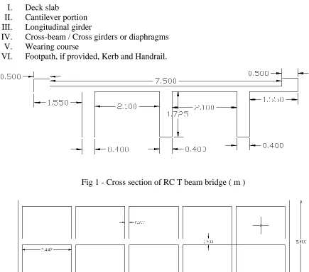
T beam bridges consist of the main longitudinal girders are designed as T-beam integral with part of the deck slab which is cast monolithically with the girders. The T-beam superstructure consists of the following components:-
I. Deck slab
II. Cantilever portion
III. Longitudinal girder
IV. Cross-beam / Cross girders or diaphragms
V. Wearing course
VI. Footpath, if provided, Kerb and Handrail.
Fig 1 - Cross section of RC T beam bridge ( m )
Available online: https://edupediapublications.org/journals/index.php/IJR/ P a g e | 3
LOADS
While designing the bridge for the road importance of following loads should be considered:-
DEAD LOAD
Structural Dead load: Structural dead loads are loads imposed on a member by its own weight and the weight of other structural elements that it supports including rail, sidewalks, slab and beam.
Superimposed dead loads: In addition to the structure Dead load, members should be designed to support the weight of superimposed dead load including footpath, wearing course, ballast, signs architectural ornamentation, pipes, cables and any other immovable appurtenances installed on the structures.
LIVE LOAD
The application of the normal live load is taken parallel to the supports. The Indian Road Congress (IRC) specified four classes of loads, designated as Class AA, Class 70 R, Class A, and Class B for the design of permanent bridges and all of them are followed in India.
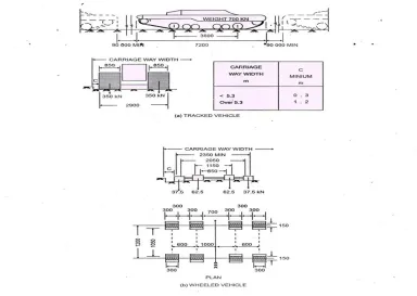
Available online: https://edupediapublications.org/journals/index.php/IJR/ P a g e | 4 Fig 3 - IRC Class AA Loadings
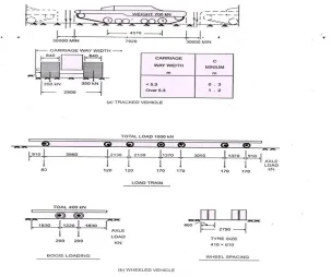
IRC Class 70R Loading: This loading consists of a tracked vehicle of 700 KN or a wheeled
vehicle of total load of 1000 KN. The wheeled vehicle is 15.22 m long and has seven axles with
Available online: https://edupediapublications.org/journals/index.php/IJR/ P a g e | 5 Fig 4 - IRC Class 70R Loading.
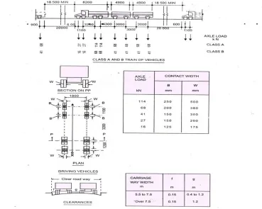
IRC Class A Loading: Class A loading is a 554 KN train of wheeled vehicle on eight axles. Class A loading normally adopted on all roads on which permanent bridges and culvert are constructed.
Available online: https://edupediapublications.org/journals/index.php/IJR/ P a g e | 6 Fig 5 - IRC Class A and B Loadings
FINITE ELEMENT ANALYSIS
Finite elements, referred to as finite elements, connected together at a number of nodes. The
finite elements method was first applied to problems of plane stress, using triangular and
rectangular element. The method has since been extended and we can now use triangular and
rectangular elements in plate bending, tetrahedron and hexahedron in three-dimensional stress
analysis, and curved elements in singly or doubly curved shell problems. Thus the finite element
method may be seen to be very general in application and it is sometimes the only valid analysis
for the technique for solution of complicated structural engineering problems. It most accurately
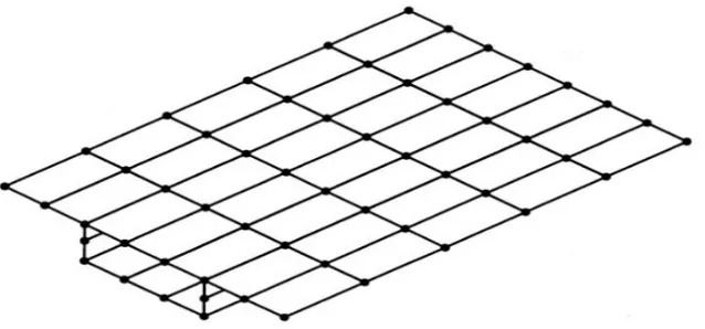
Available online: https://edupediapublications.org/journals/index.php/IJR/ P a g e | 7 Figure 6 -Three- Dimensional Structures Composed of Finite Plate Elements
Analysis of T beam bridge by Courbon’s method:
Courbon’s method:
Among these methods, Courbon’s method is the simplest and is applicable when the following conditions are satisfied:-
a) The ratio of span to width of deck is greater than 2 but less than 4.
b) The longitudinal girders are interconnected by at least five symmetrically spaced cross girders c) The cross girder extends to a depth of at least 0.75 times the depth of the longitudinal girders.
Courbon’s method is popular due to the simplicity of computations as detailed below:-
When the live loads are positioned nearer to the kerb the centre of gravity of live load acts eccentrically with the centre of gravity of the girder system. Due to this eccentricity, the load shared by each girder is increased or decreased depending upon the position of the girders.
This is calculated by Courbon’s theory by a reaction factor given by,
Where,
𝑅𝑥= Reaction factor for the girder under consideration.
I = Moment of Inertia of each longitudinal girder.
𝑑𝑥= distance of the girder under consideration from the central axis of the bridge.
Available online: https://edupediapublications.org/journals/index.php/IJR/ P a g e | 8 n = number of longitudinal girders.
e = Eccentricity of live load with respect to the axis of the bridge.
PROBLEM
Design a RCC T- beam girder bridge to suit the following data,
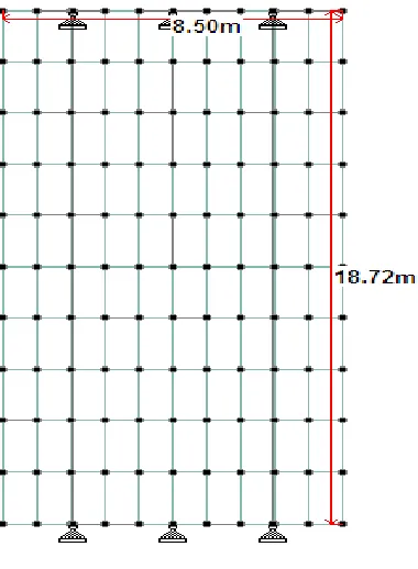
Clear width of the roadway = 7.5 m Span ( c/c of the bearing ) = 18.72 m Thickness of wearing coat = 75 m Five Cross beams at 3.742 M interval Three T-beams at 2.5M intervals
Live load = IRC tracked vehicle Loadings (for state highway)
Concrete mix M30 and Fe 415 grade HYSD bars and Clear cover = 40 mm
Using Courbon method, calculate the design moments and shears main girders and cross girders
Deck Slab
The Slab is supported on four sides by beams Thickness of Slab, H = 225MM
Thickness of Wearing Coat, D = 75MM Span in the transverse direction = 2.5M
Effective span in the Transverse direction = 2.5 - 0.4 = 2.1M Span in the Longitudinal direction = 3.742M
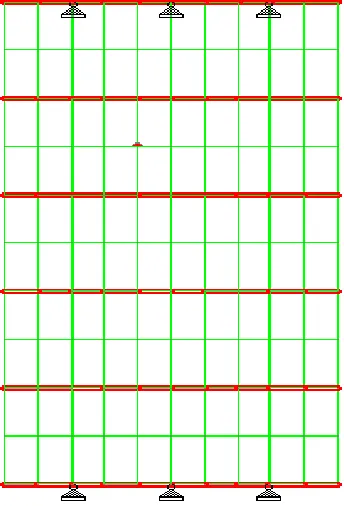
Available online: https://edupediapublications.org/journals/index.php/IJR/ P a g e | 10 Fig 8 - Plan Of longitudinal girder of T beam
Fig 9 - Plan Of Cross girder of T beam
Comparative analysis of results obtained from manual design- by Working Stress
Method verses Finite Element Method- by using Staad Pro ( Manual design v/s
Staad Pro).
Working stress method:-
Design forces due to dead load on deck slab:
Bending moment along shorter span = 4.45 kN-m
Bending moment along longer span = 2.23 kN-m
Shear force = 7.45 kN
Finite Element Method:-
Available online: https://edupediapublications.org/journals/index.php/IJR/ P a g e | 11
Working stress method:-
Design forces due to Live load on deck slab due to IRC Class AA Tracked vehicle:
Bending moment along shorter span = 30.30 kN-m
Bending moment along longer span = 14.81 kN-m
Shear force = 47 kN
Shear force = 58.75 kN (due to impact factor)
Finite Element Method:-
Design forces due to Live load on deck slab due to IRC Class AA Tracked vehicle :
Bending moment along shorter span = 24.47 kN-m
Bending moment along longer span = 12.45 kN-m
Design B.M. and S.F. on Longitudinal girder for Class AA Tracked Loadings :-
Working stress method:-
At mid span
Bending moment at outer girder = 1800 kN-m
Bending moment at inner girder = 1083 kN-m
Shear force at outer girder = 173 kN
Shear force at inner girder = 105 kN
Finite Element Method:-
Available online: https://edupediapublications.org/journals/index.php/IJR/ P a g e | 12 Bending moment at outer girder = 1845.92 kN-m
Bending moment at inner girder = 1123.25 kN-m
Shear force at outer girder = 152.17 kN
Shear force at inner girder = 85 KN
Design B.M. and S.F. on Longitudinal girder for Class A Tracked Loadings :-
Working stress method:-
At mid span
Bending moment at outer girder = 1506 kN-m
Bending moment at inner girder = 1023 kN-m
Finite Element Method:-
At mid span
Bending moment at outer girder = 1325 kN-m
Bending moment at inner girder = 1085 kN-m
Shear force at outer girder = kN
Shear force at inner girder = kN
Design of Outer Girder
1. Total Bending Moment at centre of span = 1513(𝐷𝐿) + 1800(𝐿𝐿) = 3313 𝐾𝑁 − 𝑀
2. Total Shear at support = 317.53 + 287 = 605𝐾𝑁
4. Total Shear at Mid span = 173 + 0 = 173𝐾𝑁
Design of Outer Girder (By Finite Element Method )
Available online: https://edupediapublications.org/journals/index.php/IJR/ P a g e | 13
Design of Inner Girder
1. Total Bending Moment at centre of span = 1513 + 1083 =2596 kN-m
2. Total shear at support = 620 kN
Design of Inner Girder (BY Finite Element Method)
1. Total Bending Moment at centre of span = 555.59 + 1123.25 = 1678.85 kN-m
2. Total shear at support = 410.35 kN
Design of cross-girder
Total Bending Moment = LL BM +DL BM
= 270 + 26.12 = 297 𝑘𝑁 − 𝑚
Total shear force = LL + DL SF
= 183 + 31 = 214 kN
Design of cross-girder (By Finite Element Method)
Total Bending Moment = LL BM +DL BM
= 260.27 + 25.50 = 285.77 kN-m
Total shear force = LL + DL SF
= 177.03 + 11.24 = 188.27 kN
Available online: https://edupediapublications.org/journals/index.php/IJR/ P a g e | 14
Theanalysis and design of Deck slab and T-Beam of a Bridge has been carried out manually as
per IRC guidelines and the following results have been noted.
1. Live Load due to Class AA Wheeled Vehicle produces the severest effect.
2. Shear Force due to Class AA Wheeled Vehicle is very high.
3. Bending Moment in the Inner girder is lesser than the Outer girder hence lesser
reinforcement in inner girder when compared to outer girder.
4. The design of the deck slab and T- beam has been manually done keeping in view the
above results.
With the advancement and recent development in bridge construction technologies now we
have several options to select bridge from different types , different methods of analysis and
also which full fills different parameters viz. economy, safety, stability and aesthetic view of
sub-structure. Introduction and different types of bridges considered in this review and the
selection of different type of bridges in construction technologies in civil engineering.
Among all methods, Courbon’s method is the simplest and is applicable when the conditions
are satisfied
REFERENCES
1. Indian Road congress, IRC: 6-2000, Standard Specifications and Code of Practice for
Road Bridges Section: II, Loads and Stresses, 4th revision.
2. Indian Road congress, IRC: 21-2000, Standard Specifications and Code of Practice for
Road Bridges Section: III, cement concrete (plain and reinforced), 3rd revision.
3. Dr. N. Krishna Raju, Design of Bridges ,Oxford and IBH Publishing Co. Pvt. Ltd
4. Mr. T.R. Jagadeesh and M.A. Jayaram, Design of Bridge Structures, Prentice Hall of
India Pvt. Ltd.
5. RCC Designs(Reinforced Concrete Structures) by Dr. B.C.Punmia, Ashok Kumar Jain,
Available online: https://edupediapublications.org/journals/index.php/IJR/ P a g e | 15 2319 – 1813 ISSN (p): 23-19 – 1805 || Pages || PP 67-71 || 2018 ||
7. Tangudupalli Mahesh Kumar ,J.Sudhamani, “ANALYSIS OF T-BEAM DECK SLAB
BRIDGE IN DIFFERENT METHODS”, International Journal For Technological Research In Engineering Volume 4, Issue 12, August-2017.
8. R.Shreedhar, Shivanand Tenagi, “Comparative study of T-beam bridge longitudinal
girder design using IRC 112:2011 and IRC 21:2000”, International Journal of Scientific & Engineering Research, Volume 6, Issue 8, August-2015 ISSN 2229-5518
9. Y. Kamala Raju, R.Mehar Babu, Mohd. Husssain, “Reinforced Cement Concrete
Bridge Deck Design of a Flyover with Analysis for Dynamic Response Due To Moving Loads for Urban Development in Transportation Systems” Vol 3, Issue 2,February 2018.
10.L.P.Huang, S.G.Cao2, C.L.Wei, Z.G.Chang, X.C.Zhang and Y.Z.Huang, “Load
Distribution Factor before and after Widening of Existing T-beam Bridges”, Journal of Engineering Science and Technology Review 10 (3) (2017)
11.Abrar Ahmed, Prof. R.B. Lokhande, “COMPARATIVE ANALYSIS AND DESIGN OF
T-BEAM AND BOX GIRDERS”, Volume: 04 Issue: 07 | July-2017
12.Bridge Design using the STAAD.Pro/Beava”, IEG Group, Bentley Systems, Bentley
Systems Inc., March 2008.
13.“Bridge Deck Analysis” by Eugene J O‟Brien and Damien and L Keogh, E&FN Spon,
London.
14.“Bridge Deck Behavior” by Edmund Hambly, Second Edition, Chapman & hal India,
Madras.