A SAR AUTOFOCUS ALGORITHM BASED ON PARTICLE SWARM OPTIMIZATION
T. S. Lim, V. C. Koo, H. T. Ewe, and H. T. Chuah
Faculty of Engineering & Technology Multimedia University
Jalan Ayer Keroh Lama, Bukit Beruang, 75450 Melaka, Malaysia
Abstract—In synthetic aperture radar (SAR) processing, autofocus techniques are commonly used to improve SAR image quality by removing its residual phase errors after conventional motion compensation. This paper highlights a SAR autofocus algorithm based on particle swarm optimization (PSO). PSO is a population-based stochastic optimization technique based on the movement of swarms and inspired by social behavior of bird flocking or fish schooling. PSO has been successfully applied in many different application areas due to its robustness and simplicity [1–3]. This paper presents a novel approach to solve the low-frequency order polynomial and high-frequency sinusoidal phase errors. The power-to-spreading noise ratio (PSR) and image entropy (IE) are used as the focal quality indicator to search for optimum solution. The algorithm is tested on both simulated two-dimensional point target and real SAR raw data from RADARSAT-1. The results show significant improvement in SAR image focus quality after the distorted SAR signal was compensated by the proposed algorithm.
1. INTRODUCTION
The uncompensated along-trackmotions errors can cause a severe loss of geometry accuracy and degrade SAR image quality. In a typical airborne SAR system, an inertia navigation unit (INU) and a global positioning system (GPS) are employed to provide real-time data for motion error compensation. After conventional motion compensation,autofocus techniques are widely used to improve image focus. Autofocus refers to the computer-automated estimation and compensation of residual phase errors in SAR imagery.
Basically phase errors may be categorized as low-frequency phase errors and high-frequency phase errors. The detail classification of phase errors can be found in [4]. Depending on its nature and magnitude, phase errors can significantly degrade the image quality in terms of geometry linearity, resolution, image contrast, and signal-tonoise ratio (SNR). Basically the low-frequency phase errors affect the mainlobe of the system impulse response while high-frequency phase errors affect the sidelobe region.
Many autofocus algorithms have been proposed and developed since the early SAR development. A common approach in existing autofocus algorithms is to model the phase error as one-dimensional multiplicative noise in the azimuth domain. In general, autofocus techniques can be divided into two groups, namely model-based and non-parametric. Model-based autofocus techniques estimate the coefficients of an expansion that models the phase error. Elementary model-based autofocus may determine only the quadrature phase error (QPE), while more elaborate methods estimate higher order polynomial-like phase errors as well. The mapdirft (MD) and multiple aperture mapdrift (MAM) are examples of model-based autofocus algorithms for low-frequency phase errors compensation [5]. The MD and MAM’s performance is only guaranteed if the phase error estimated is correctly modeled. However, these types of techniques are often unable to extract high-frequency phase errors due to the complexity of the problem.
nonparametric algorithms apply mainly to spotlight SAR imagery. The autofocus algorithm for spotlight mode imagery cannot be directly applied to imagery formed by the conventional stripmap mode. The main difference is that in the spotlight mode, the individual target apertures coincide, but in the stripmap case the apertures are offset from each other.
This paper proposes a non-parametric autofocus algorithm for motion compensation in SAR imaging based on particle swarm optimization. It is an algorithm that capable to minimize both the low-frequency polynomial-like phase errors and high-low-frequency sinusoidal phase errors in a distorted SAR signal. Furthermore, it is applicable to spotlight and stripmap SAR imagery.
2. SYSTEM MODEL
Consider a SAR system that travels along cross-range (y) direction. Thexdirection (slant-range) is the direction perpendicular to the flight path of the radar platform andkxas it corresponding spatial frequency,
the SAR raw signal s(x, y) can be defined as [8]:
s(x, y) =
r(xi, yi)g(x−xi, y−yi, xi)dxidyi (1)
where r(·) is the surface reflectivity pattern, and g(·) is the impulse response of the system (the return due to a unity point scatterer).
The uncompensated or distorted SAR raw signal (Sme) in two-dimensional (kx, y) domain is defined as
sme(kx, y) =
r(xi, yi)e−jkxxig(kx, y−yi, xi)ejθedxidyi (2) where θe(·) is a two-dimensional multiplicative phase error in (kr, y)
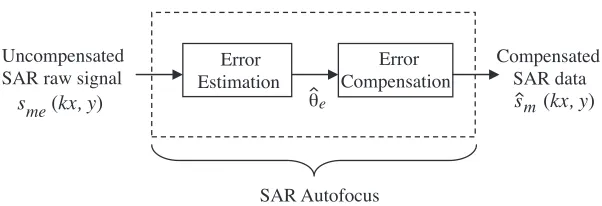
domain. The SAR autofocus algorithm is to determine or estimate the phase error θe(·) based on the uncompensated SAR raw signal. The
phase errors of the distorted SAR raw signal can then be minimized from the estimated phase error of the autofocus algorithm. Figure 1 shows the basic blockdiagram of a typical SAR autofocus algorithm.
e
Uncompensated SAR raw signal
s me(kx, y)
Error
Estimation Compensation
Error Compensated
SAR data
s m(kx, y)
SAR Autofocus
θ> >
Figure 1. Blockdiagram of a typical SAR autofocus.
major cause of phase errors. This assumption makes the phase error separable from the integral of Eq. (2). The second assumption relies on the fact that the effects of azimuth (cross-range) phase errors are generally more dominant than the range phase errors. With these assumptions, the perturbed SAR raw signal in range-compressed domain is given by
se(yb) =|sa(yb)|ej(φa(yb)+θe(yb)) a= 1,2, . . . , A; b= 1,2, . . . , B (3)
where subscript a refers to the ath range bin, yb is the bth azimuth
position along the synthetic aperture for Arange bins and B azimuth positions of a discrete sample of SAR image. The magnitude and phase of the range-compressed data for range binaare defined by|sa(yb)|and φa(yb), respectively. The uncompensated phase errors, θe is assumed
common to all range bins and independent ofa. Therefore, the vector of phase errors,ϕ
e is given by: ϕ
e= [0, θe(y2), . . . , θe(yb)] (4)
Low-frequency phase error is one having a period larger than the coherent processing interval [9]. Motion measurement errors are the primary source of lowfrequency phase errors. A practical model to describe these errors in azimuth domain of theK-th order polynomial is given as:
θeLF(y) =
K
k=1
akyk −Lsyn
2 ≤y≤
Lsyn
2 (5)
whereakis the unknown coefficient ofK-th order polynomial error and Lsyn is the synthetic aperture length. Basically, linear phase error will
errors do not affect SAR image focus, the error model in Eq. (5) does not include zero-order term.
In addition, high-frequency sinusoidal phase errors have more rapid variations over the coherent aperture [9]. The major source of high-frequency phase errors is uncompensated vibration of the antenna phase center. A practical model to describe the high-frequency sinusoidal phase errors,θeHF(y) in azimuth domain is given in [4] and
can be rewritten as follows:
θeHF(y) =
Nh
k=1
Rkcos(ωky) (6)
ωk =
2πfs
N k (7)
wherefsis defined as sampling frequency of the signal,N is the number of discrete sample points, Rk is random noise amplitude at harmonic
frequencyωkandNhis the total number of effective harmonics inθeHF.
In order to minimize the phase errors, the taskof the proposed algorithm is to find the best estimate of θeLF and θeHF from the
distorted or uncompensated SAR raw data, se. In this paper, the
effects of the low-frequency phase errors and high-frequency sinusoidal phase errors will be analysed and the proposed algorithm will be utilized to recover the phase errors.
The proposed algorithm not only tested in two-dimensional simulated data but also verified in actual SAR raw data extracted from RADARSAT-1. The phase errors estimation is formulated as a nonlinear optimization problem for both the low-frequency high-order polynomial and high-frequency sinusoidal phase errors. These problems are difficult to solve using traditional search techniques because of its multimodal, non-convex nature, resulting in multiple local minima.
3. PARTICLE SWARM OPTIMIZATION BASED AUTOFOCUS (PSOA)
since all particles in PSO are kept as members of the population through the course of the searching process. Each particle in the swarm is influenced by its own successful experiences as well as the successes experiences of other particles. In a PSO algorithm, the particles are flying through multidimensional search space and have two essential reasoning capabilities: their memory of their own best position and knowledge of the swarm’s best position. A fitness function needs to be defined in PSO algorithm to quantify the performance of each particle. All the encountered positions of the particles are evaluated by the fitness function to represent how well the particle satisfies the design parameters. Finally, most the particles converge to global optimum, which is expected to be the best desire result.
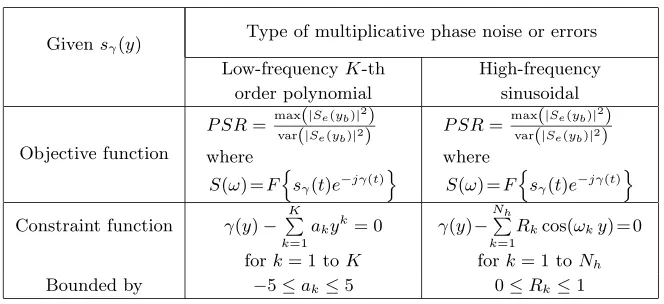
The PSR is used as the focal quality indicator to search for global optimum solution in the SAR phase errors problem. The relationship between peakpower, spreading noise and Nh for SAR system can be found in [4]. The objective and constraint functions of the PSO based SAR autofocus algorithm for low-frequencyK-th order polynomial and high-frequency sinusoidal phase errors may be summarized in Table 1. The goal is to determine optimum solution that yields maximum PSR.
Table 1. The objective and constraint functions of the PSO based SAR autofocus.
Givensγ(y)
Type of multiplicative phase noise or errors
Low-frequencyK-th order polynomial
High-frequency sinusoidal
Objective function
P SR=max(|Se(yb)|2)
var(|Se(yb)|2) where
S(ω) =F
sγ(t)e−jγ(t)
P SR=max(|Se(yb)|2)
var(|Se(yb)|2) where
S(ω) =F
sγ(t)e−jγ(t)
Constraint function γ(y)−
K
k=1
akyk= 0 γ(y)−
Nh
k=1
Rkcos(ωky) = 0
fork= 1 toK fork= 1 toNh
Bounded by −5≤ak≤5 0≤Rk≤1
The fitness function is a combination of the objective and constraint functions as given in the following equation:
For low frequencyK-th order polynomial phase errors:
θLF =P SR−E
γ(y)−
K
k=1
akyk
For high-frequency sinusoidal phase errors:
θHF =P SR−E
γ(y)−
Nh
k=1
Rkcos(ωky)
(9)
whereE[x] =|x|denotes the constraint violation errors.
The PSO algorithm in conjunction with a local improvement procedure for estimating low-frequency polynomial and high-frequency sinusoidal phase errors can be found in [4] and may be summarized as: 1. Initialize a population of the potential solutions, called “particles”, and each particle is assigned a randomized velocity and position. 2. Evaluate the fitness value for each solution vector using Eqs. (8)
and (9) to find the best solution which minimizeθe.
3. Update the velocity and position of the particles according to the following equations:
Vidt+1=ω×Vidt+c1×rand1×(pid−xtid)+c2×rand2×(pgd−xtid) (10) xtid+1=xtid+Vidt+1 (11) where c1 and c2 are two positive acceleration constants
representing a “cognitive” and a “social” component, respectively;
ω is an inertia weight and rand1 and rand2 are two independent
uniform random numbers. The velocity of each particle is updated according to its previous velocity (Vid), the personal best location of the particle (pid) and the global best location (pgd).
4. Repeat steps 2–3 until the best solution is achieved, or a specified maximum number of iterations is reached.
In actual implementation, the program was developed using MATLAB 6.5 application software running on an Intel Centrino Duo at 1.6 GHz laptop with 1 GB memory.
4. RESULTS AND DISCUSSIONS
In order to evaluate the performance of the proposed autofocus algorithm, the following two standard tests are applied:
i) Two-dimensional (2-D) simulated SAR image test for point target. ii) Two-dimensional (2-D) actual SAR image test (raw data extracted
from RADARSAT-1).
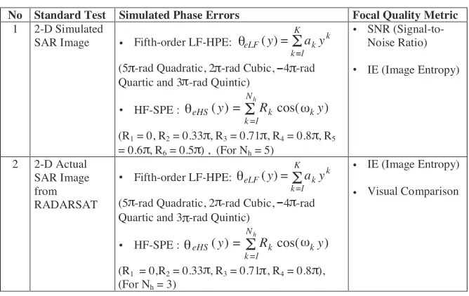
test, two most common phase errors, namely low-frequency high-order polynomial phase errors (LF-HPE), and high-frequency sinusoidal phase errors (HF-SPE) are introduced into the system. The low-frequency quadrature phase error is not included in the tests due to this type of error can be easily removed by conventional model-based autofocus techniques such as Mapdrift algorithm [5]. Table 2 shows the summary of the two standard tests setup of the proposed algorithm corrupted by LF-HPE and HF-SPE.
Table 2. Two standard tests setup of the PSO based autofocus algorithm.
No Standard Test Simulated Phase Errors Focal Quality Metric
1 2-D Simulated
SAR Image Fifth-order LF-HPE:
=
= K k
k k
eLF y a y
1 ) (
(5( -rad Quadratic, 2( -rad Cubic, 4( -rad Quartic and 3( -rad Quintic)
HF-SPE : = = h N k k k
eHS y R y
1 ) cos( ) (
(R1 = 0, R2= 0.33( , R3 = 0.71 , R4 = 0.8( , R5 = 0.6( , R6 = 0.5 ) , (For Nh= 5)
SNR (Signal-to- Noise Ratio)
IE (Image Entropy)
2 2-D Actual SAR Image from RADARSAT Fifth-order LF-HPE: = = K k k k
eLF y a y
1 ) (
(5( -rad Quadratic, 2( -rad Cubic, 4( -rad Quartic and 3( -rad Quintic)
HF-SPE :
= = h
N
k k k
eHS y R y
1
) cos( )
(
(R1 = 0,R2= 0.33( , R3= 0.71( , R4 = 0.8( ), (For Nh = 3)
IE (Image Entropy)
Visual Comparison θ θ
Σ
Σ
π π π π θΣ
ω ω θΣ
π π π π π π π π π π π π . . . . . . . .4.1. Two-dimensional Simulated SAR Image Test
in discrete form, an approximation of the IE [12, 13] is given as:
IE=−
M−1
m=0
N−1
n=0
sm, nlnsm, n (12)
wheresm, n is the normalized target reflectivity of an image.
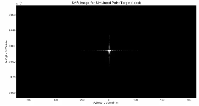
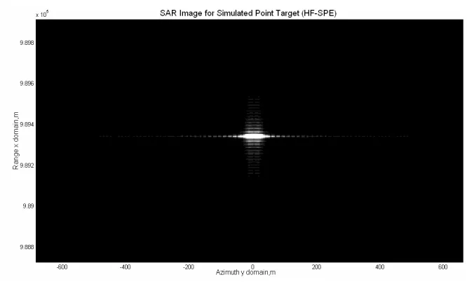
Figure 2 illustrates a simulated SAR image of an ideal 2-D SAR signal for a point target processed by Range-Doppler Algorithm (RDA). Figure 3 and Figure 4 show a simulated 2-D SAR image for point target corrupted by low-frequency high-order polynomial and high-frequency sinusoidal phase errors respectively. The number of both range and azimuth samples in the simulation test is 1024. As depicted in Figure 3, the LF high-order polynomial phase errors defocus the mainlobe and cause minor distortion in the sidelobes regions of the point target. It can also be observed that the HF sinusoidal phase errors cause pair echoes to appear as spurious targets as shown in Figure 4.
Figure 2. Ideal 2-D SAR image.
can be observed where spurious targets caused by HF-SPE have almost totally been eliminated.
Figure 3. 2-D SAR image corrupted by LF-HPE.
Figure 4. 2-D SAR image corrupted by HF-SPE.
by PSO based autofocus algorithm. From Table 3, it is found that higher SNR and lower IE value are obtained for the simulated 2-D SAR image as a result of the minimization of the phase errors by PSO based autofocus algorithm. (It should be noted that the smaller value of IE indicates better focus of the image).
Figure 5. 2-D SAR image corrupted by LF-HPE (compensated by PSO autofocus).
Table 3. SNR and IE of the simulated 2-D SAR image.
Standard Test 1 5-th order LF-HPE HF-SPE (Nh=5) SNR (dB) IE SNR (dB) IE
1 2-D Simulated SAR
Image (Ideal) 9.2596 7.72792 9.2596 7.72792
2
2-D Real SAR Image (Corrupted by
phase errors)
8.8315 8.73471 8.8491 9.52160
3
2-D Real SAR Image (Compensated by PSO based autofocus
algorithm)
Figure 6. 2-D SAR image corrupted by HF-SPE (compensated by PSO autofocus).
(a)
(b)
4.2. Two-dimensional Actual SAR Image Test
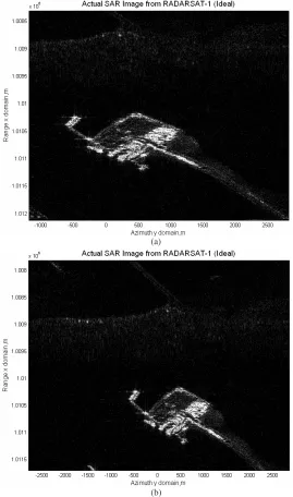
In order to further verify the effectiveness of the proposed algorithm, a particular set of real SAR raw data [14] extracted from an existing space-borne SAR sensor (RADARSAT-1) is employed. The image entropy is used again as a measure of the image quality. However, the SNR is not used in this test as thesignal and noise is no longer clear in the case of natural terrains of actual SAR image. RADARSAT-1 is Canada’s first commercial Earth observation satellite and was launched in 1995. It uses a SAR sensor to image the Earth at a single frequency of 5.3 GHz (C band) and its data are stored in Committee of Earth Observations Satellites (CEOS) format. For this test, only a selected portion (a port and bridge) of the fully processed image (Vancouver, Canada) of RADARSAT-1 SAR raw data is employed as shown in Figure 7.
As shown in Table 2, the raw data of selected portion are corrupted by LFHPE and HF-SPE and the proposed algorithm is applied subsequently to minimize the phase errors. Figure 8 shows a processed SAR image of the selected portion of the RADARSAT-1 SAR raw data processed by RDA. In addition, Figure 9 and Figure 10 show the same SAR images but corrupted by the LF-HPE and HF-SPE respectively. As illustrated in Figure 9, the LF-HPE defocuses the image but the basic shape of the image (a port and bridge) still can be maintained. This is due to the fact the LF-HPE mainly defocus the mainlobe without affects much on the sidelobe regions. The degree of distortion depends on the number of order and value of the coefficients of LF-HPE. Figure 10 shows that the HF-SPE create a lot spurious targets (ghost image) as the effects of the pair echoes. On the other hand, Figures 11 and 12 show the compensated SAR images from RADARSAT-1 raw data by using PSO based autofocus algorithm which was corrupted by LF-HPE and HF-SPE respectively. The visual inspection of Figure 11 as compared to Figure 9 shows a little improvement in the image focus quality since the LF-HPE (up to fifth-order for this case) did not introduce high degree of distortion of SAR image as compared to HF-SPE. However, when compared the Figure 12 to Figure 10 by visual inspection, significant image focus quality improvement can be observed where most of the spurious targets (ghost image) caused by HF-SPE have been removed.
Figure 9. SAR image from RADARSAT-1 raw data corrupted by LF-HPE.
Figure 11. SAR image from RADARSAT-1 raw data corrupted by LF-HPE (compensated by PSO autofocus).
Table 4. IE of the RADARSAT-1 SAR image.
Standard Test 2 5-th order LF-HPE HF-SPE (Nh=3)
IE IE
1 2-D Simulated SAR
Image (Ideal) 16.5837 16.5837
2
2-D Real SAR Image (Corrupted
by phase errors)
17.9090 18.5361
3
2-D Real SAR Image (Compensated
by PSO based autofocus algorithm)
16.7166 17.1098
Based on results of the standard test 1 and 2, it is clearly shown that the proposed PSO based autofocus algorithm is a non-parametric and capable of estimating all types of phase errors in two-dimensional space. The strength of the PSO derives from the interactions among particles as they search the problem space collaboratively [15]. The main reason for the success of PSO algorithm lies in its particles ability to communicate information they find about each other by updating their velocities in terms of local and global bests.
5. CONCLUSION
A SAR non-parametric autofocus algorithm based on particle swarm optimization has been presented. The proposed algorithm is capable of estimating both low-frequency and high-frequency of phase errors in two-dimensional space. It is also applicable to stripmap SAR imagery. The simulated and real SAR raw data testing results clearly show that the proposed algorithm is effective to minimize both the low-frequency high-order polynomial and high-frequency sinusoidal phase errors.
REFERENCES
1. Naka, S., T. Genji, T. Yura, and Y. Fukuyama, “A hybrid particle swarm optimization for distribution state estimation,” IEEE Trans. Power Syst., Vol. 18, 60–68, 2003.
2. Gaing, Z., “A particle swarm optimization approach for optimum design of PID controller in AVR system,” IEEE Trans. Energy Conv., Vol. 19, 384–391, 2004.
optimization scheme to the design of electromagnetic absorbers,” IEEE Trans. Antennas Propag., Vol. 53, No. 11, 384–391, 2005. 4. Lim, T. S., V. C. Koo, H. T. Ewe, and H. T. Chuah,
“High-frequency phase error reduction in SAR using particle swarm optimization,”J. of Electromagn. Waves and Appl., Vol. 21, No. 6, 795–810, 2007.
5. Mancill, C. E. and J. M. Swiger, “A mapdrift autofocus technique for correcting higher order SAR phase errors,” 27th Annual Tri-Service Radar Symposium Record, 391–400, Monterey, CA, 1981. 6. Jakowatz, C. V. and D. E. Wahl, “Eigenvector method for
maximum-likelihood estimation of phase errors in synthetic aperture radar imagery,” Optics Letters, Vol. 10, No. 12, 2539– 2546, 1993.
7. Wahl, D. E., P. H. Eichel, D. C. Ghiglia, and C. V. Jakowatz, “Phase gradient autofocus — A robust tool for high resolution SAR phase correction,” IEEE Transactions on Aerospace and Electronic System, Vol. 30, No. 3, 827–835, 1994.
8. Koo, V. C., Y. K. Chan, V. Gobi, T. S. Lim, B. K. Chung, and H. T. Chuah, “The MASAR project: Design and development,” Progress In Electromagnetics Research, Vol. 50, 279–298, 2005. 9. Carrara, W. G., R. S. Goodman, and R. M. Majewski,
Spotlight Synthetic Aperture Radar: Signal Processing Algorithms, Chapter 5, 203–243, Artech House, 1995.
10. Kennedy, J. and R. C. Eberhart, “Particle swarm optimization,” Proc. IEEE International Conference on Neural Networks, Vol. 4, 1942–1948, 1995.
11. Koo, V. C., T. S. Lim, M. C. Rao, and H. T. Chuah, “A GA-based autofocus technique for correcting high-frequency SAR phase error,”J. of Electromagn. Waves and Appl., Vol. 18, No. 6, 781–795, 2004.
12. Koo, V. C., Y. K. Chan, and H. T. Chuah, “Multiple phase difference method for real-time SAR autofocus,” J. of Electromagn. Waves and Appl., Vol. 20, No. 3, 375–388, 2006. 13. Nikhil, P. R. and P. K. Sankar, “Entropy: A new definition and
its applications,” IEEE Trans. on System, Man and Cybernetics, Vol. 21, No. 5, 1260–1270, 1991.
14. Cumming, I. G. and F. H. Wong, Digital Processing of Synthetic Aperture Radar Data, Artech House Inc., 2005.