University of South Florida
Scholar Commons
Graduate Theses and Dissertations Graduate SchoolApril 2018
Multi-Objective Resource Provisioning in Network
Function Virtualization Infrastructures
Diogo Oliveira
University of South Florida, [email protected]
Follow this and additional works at:http://scholarcommons.usf.edu/etd Part of theComputer Engineering Commons
Scholar Commons Citation
Oliveira, Diogo, "Multi-Objective Resource Provisioning in Network Function Virtualization Infrastructures" (2018).Graduate Theses and Dissertations.
Multi-Objective Resource Provisioning in Network Function Virtualization Infrastructures
by
Diogo Oliveira
A dissertation submitted in partial fulfillment of the requirements for the degree of
Doctor of Philosophy
Department of Electrical Engineering College of Engineering
University of South Florida
Co-Major Professor: Nasir Ghani, Ph.D. Co-Major Professor: Jorge Crichigno, Ph.D.
Richard Gitlin, Sc.D. Stephen Saddow, Ph.D.
Kaiqi Xiong, Ph.D.
Date of Approval: March 20, 2018
Keywords: Virtual Network Function, Placement Problem, Risk-Aware
Dedication
To my wife, Elisa Oliveira, for all the support, braveness, understanding and love. To my daughters, Ana Clara and Emily Oliveira, for the unconditional love.
Acknowledgments
I would like to acknowledge and dedicate my gratitude to the following people who made the completion of this work possible: Most specially, my wife, Elisa, and my daughters, Ana Clara and Emily, for their unconditional love and support.
My supervisor, Dr. Nasir Ghani, for his continuous help and advisement through my Ph.D. study.
My former co-supervisor and committee member, Dr. Stephen Saddow, for believing in me and giving me the chance to join the University of South Florida as a visiting scholar. My co-supervisor, Dr. Jorge Crichigno, for the contribution and continuous assess-ment through my research.
My dissertation committee members, Dr. Richard Gitlin and Dr. Kaiqi Xiong, for their valuable suggestions and advice on this dissertation work.
My former and current research colleagues, Dr. Hao Bai, Dr. Mahsa Pourval, M.E. Amanda Gonzalez, M.E. Farooq Shaikh, M.E. Andrea Wright, Dr. Mohammed Jasim, M.E. Nazlee Siasi and Mr. Akhil Arra, for their collaboration.
My former research colleagues, Dr. Tom Lehman and Dr. Xi Yang for the contribution during our collaborative research.
My father, for being such an inspiration as a person and professional.
Table of Contents
List of Tables iii
List of Figures iv Abstract vi Chapter 1 Introduction 1 1.1 Background Overview 1 1.2 Motivations 5 1.3 Problem Statement 7
1.4 Proposed Work and Contributions 7
Chapter 2 Background and Related Work 9
2.1 Network Function Virtualization Overview 9
2.2 VNF Placement 12
2.3 NFV Survivability 18
2.3.1 Single Failure Scenarios 19
2.3.2 Multi-Failure Scenarios 22
2.4 Open Challenges 25
Chapter 3 Joint VNF Placement and Routing with Traffic Engineering 26
3.1 Notation Overview 27
3.2 Multi-Objective Minimized Link Load ILP (MLL-ILP) Model 28
3.3 MLL-ILP Complexity 32
3.4 MLL-GR Heuristic 33
3.5 MLL-GR Complexity 36
3.6 Performance Evaluation 38
3.6.1 Weighting Factors Selection (First Testcase) 40
3.7 Under-Resourced Scenarios (Second Testcase) 42
Chapter 4 Survivable Joint VNF Placement and Routing 53
4.1 Notation Overview and Failure Model 54
4.2 “Risk-Aware” Network Function Placement and Routing 56
4.2.1 “Risk-Aware” Optimization Model (RA-ILP) 57
4.3 Performance Evaluation 60
4.3.1 Pre-Fault Performance 61
4.3.2 Post-Fault Performance 62
Chapter 5 Multi-Objective Metaheuristic Scheme for Large-Scale Networks 71
5.1 Overview of Genetic Algorithm Metaheuristic 71
5.2 Genetic Algorithm Approach for NFV Provisioning 74
5.2.1 Notation Overview 74
5.2.2 “Risk-Aware” Genetic Algorithm (RA-GEN) Scheme 75
5.3 Performance Evaluation 79
5.3.1 Pre-Fault Performance 80
5.3.2 Post-Fault Performance 80
Chapter 6 Conclusions and Future Work 85
6.1 Summary of Research Findings 86
6.1.1 Future Work 90
References 91
List of Tables
Table 3.1 List of variables 29
Table 3.2 Testcases parameters 39
Table 4.1 List of variables 55
Table 4.2 Multi-failure testcases parameters 61
Table 5.1 List of variables 75
Table 5.2 Multi-failure testcases parameters 79
List of Figures
Figure 1.1 Service Function Chaining. 4
Figure 1.2 Network Function Virtualization overview. 5
Figure 2.1 VNF placement overview 13
Figure 2.2 A summary of VNF placement and survivability efforts 14
Figure 3.1 MLL-GR heuristic algorithm 37
Figure 3.2 NSF network topology. 38
Figure 3.3 First testcase: a) average deployment cost for differentw2 and w3weights
b) average routing cost for different w2 and w3 weights 46
Figure 3.4 First testcase: a) average deployment cost and b) average routing cost 47
Figure 3.5 Second testcase: a) satisfied NFs, and b) deployment cost 48
Figure 3.6 Second testcase: a) routing cost, and b) number of links 49
Figure 3.7 Third testcase: satisfied NFs: a) MLL-ILP and JRP-ILP, b) MLL-GR
and JRP-GR 50
Figure 3.8 Third testcase: MLL schemes a) deployment cost, and b) routing cost 51
Figure 3.9 Third testcase: number of links - MLL-ILP and MLL-GR. 52
Figure 4.3 NSF network topology and the respective failure regions. 60
Figure 4.4 NSF network topology and the respective failure regions. 63
Figure 4.5 a) deployment costs, and b) routing costs 66
Figure 4.6 Requests assignment failures for the idealistic stressor scenario) RA-ILP
and MLL-ILP, and b) RA-GR and MLL-GR 67
Figure 4.7 Link failure rates for the idealistic stressor scenario) RA-ILP and
MLL-ILP, and b) RA-GR and MLL-GR 68
Figure 4.8 Requests assignment failures for the realistic stressor scenario a) RA-ILP
and MLL-ILP, and b) RA-GR and MLL-GR 69
Figure 4.9 Link failure rates for the realistic stressor scenario a) RA-ILP and
MLL-ILP, and b) RA-GR and MLL-GR 70
Figure 5.1 Genetic algorithm (GA) flow chart 73
Figure 5.2 RA-GEN metaheuristic algorithm 82
Figure 5.3 a) deployment costs, and b) routing costs 83
Figure 5.4 Requests assignment failures for the a) idealistic stressor scenario, and
Abstract
Network function virtualization (NFV) and software-defined networking (SDN) are two recent networking paradigms that strive to increase manageability, scalability, pro-grammability and dynamism. The former decouples network functions and hosting devices, while the latter decouples the data and control planes. As more and more service providers adopt these new paradigms, there is a growing need to address multi-failure conditions, particularly those arising from large-scale disaster events. Overall, addressing the virtual
network function (VNF) placement and routing problem is crucial to deploy NFV
surviv-ability. In particular, many studies have inspected non-survivable VNF provisioning, however no known work have proposed survivable/resilient solutions for multi-failure scenarios.
In light of the above, this work proposes and deploys a survivable multi-objective provisioning solution for NFV infrastructures. Overall, this study initially proposes multi-objective solutions to efficiently solve the VNF mapping/placement and routing problem. In
particular, a integer linear programming (ILP) optimization and a greedy heuristic
meth-ods try to maximize the requests acceptance rate while minimizing costs and implementing
traffic engineering (TE) load-balancing. Next, these schemes are expanded to perform
services. Furthermore, additionally to the ILP optimization and greedy heuristic schemes, a metaheuristic genetic algorithm (GA) is also introduced, which is more suitable for
large-scale networks. Overall, these solutions are then tested in idealistic and realistic stressor scenarios in order to evaluate their performance, accuracy and reliability.
Chapter 1 Introduction
This dissertation presents a multi-objective resources provisioning in network func-tion virtualizafunc-tion infrastructures, which focuses on virtual network funcfunc-tion placement and routing with a focus on survivability under large-scale disaster conditions. This initial chap-ter starts by introducing some of the key developments in this space and then presents the key motivations for the work. The main contributions of the research are then presented in a high-level manner along with an overview of the remainder of the thesis.
1.1 Background Overview
The past three decades have seen rapid technological achievements in the networking
and information technology (IT) space. These developments have occurred not only in
computational power, but also in terms of data rate transmission and storage as well. In turn, these advances have led to much lower acquisition, deployment and maintenance costs. These improvements have led to the adoption of large-scale datacenters interconnection, and the broader emergence of cloud-computing paradigms. However, as these trends have unfolded, a host of management and orchestration ossification challenges have also arisen.
Now traditional physical network devices, e.g., such as switches and routers, have operated with their own specialized internal and standalone control plane configuration
sys-tems; i.e., vendor-proprietary. These setups led to increase management complexity due to individual configuration requirements and a high degree of vendor dependency. As a result, many carriers began to find it very difficult to build and offer cost-effective servers using legacy devices. In response, various organizations initiated efforts to simplify network node designs by decoupling the control and data planes, i.e.,software-defined networking (SDN).
The main premise behind SDN outsource the control plane to a concentrator, namely SDN controller. The controller is responsible for receiving the flow rules via northbound interface and pushing such rules into the proper network nodes via southbound interface. Overall, SDN strives to reduce network ossification as well as reducing operational and capital ex-penses (OpEx and CapEx) by reducing management complexity and improving dynamism. Additionally, the adoption of SDN nodes leverages vendor-independency.
Now, although decoupling the control and data planes delivers the aforementioned advantages, traditional network services deployment still remains a complex and expensive under-taking. Moreover there is a high degree of vendor-dependency as traditional network services are managed and deployed by embedded vendor-proprietary systems. Therefore, in order to reduce network services management complexity and to improve (re)deployment
capabilities, network function virtualization (NFV) paradigm has been evolved to support
deployment of network functions oncommercial-of-the-shelf (COTS) equipment as a software
In general, typical client networking services can include a range of offerings such as firewalls, deep packet inspection (DPI) engines, intrusion detection/prevention systems,
network address translation (NAT) boxes, etc. Now in terms of NFV, many of these services
are typically composed of multiple virtual network functions (VNF). Specifically VNF can
be deployed/implemented across multiple datacenter sites, and a datacenter site can host multiple VNFs. Additionally, many client services may impose a strict interdependent
rela-tionship between multiple atomic VNFs, i.e.,service function chaining (SFC). For example,
a firewall service can be comprised of two VNFs to filter packets and balance traffic (load balancer). Fig. Figure 1.1 also illustrates a generic set of three SFC demands, i.e., SFC1 (red) consists of VNFs 1 and 3, SFC2 consists of VNFs 1, 2 and 3 and SFC3 consists of VNFs 2 and 3. In an event of a failure of Datacenter D, services demanding VNF1 are steered to Datacenter D, which deploys a backup instance of VNF1.
Although it is not mandatory, in general most deployments use an embedded
vir-tual network as the virtual network function infrastructure (VNFI) owing the advantages
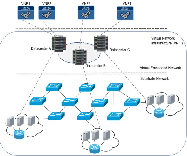
offered by this approach. In particular, it is possible to map and deploy VNFs in a substrate infrastructure comprised of nodes that support the VNF paradigm. However a virtual net-work guarantees a more flexible and manageable infrastructure. Specifically, Fig. Figure 1.2 shows a VNFI comprised of a virtual network embedded into a substrate/physical network, where the substrate nodes are COTS devices hosting virtual nodes that instantiate the VNFs illustrated in the NFV layer.
Figure 1.1: Service Function Chaining.
However as service providers show increasing interest in NFV, many further questions and challenges are starting to arise, i.e., such as management and orchestration, security and privacy, performance, and function placement, among others. In particular, the latter placement problem must consider a multiple set of client requests, where each request is comprised of a set of VNFs, a source, a destination and a minimum bandwidth rate. Hence, the service providers must efficiently ”place” these VNFs across their datacenters to reduce deployment and routing costs, and also increase service performance and reliability.
Now given the immense interest and focus on network virtualization, the VNF place-ment problem has been well-studied in recent years. Specifically, researchers have proposed a host of schemes to minimize costs, increase revenues or increase reliability [BA01]-[DO02]. Additional studies have also looked at survivable VNF placement using backup VNF
re-Figure 1.2: Network Function Virtualization overview.
source provisioning [MB01][ZY01][WD01]. In general, these studies have used a wide range of techniques, including optimization, graph-theoretic heuristics, meta-heuristics, and vari-ous approximation strategies, see [ZY01] for details.
1.2 Motivations
requests are provisioned based upon the current available resource levels in the network. However, as more providers start to deploy NFV-based services, related survivability is-sues are becoming increasingly important. Now traditionally, network operators have relied upon dedicated, expensive hardware systems to deliver a ”carrier-grade” reliability for their high-end clients. Clearly, achieving similar performance over commodity-based servers (im-plementing NFV) is a much more challenging task as such systems have generally lower reliability levels. Hence operators have to derive effective strategies to achieve acceptable survivability support in emerging NFV service setups.
Although some efforts have addressed NFV survivability topics, these solutions mostly focus on single isolated system failures. As a result, the further impact of large-scale disaster events (multiple failures) on NFV-based services becomes a concern. These occurrences can include events such as natural disasters, malicious attacks, and cascading power outages.
Now the only known work on ”risk-aware” disaster-based NFV provisioning is pre-sented in [JF01], which outlines the probabilistic availability of a path based on the actual temporal availability of physical resources. Indeed there is a growing need to build more sys-tematic multi-objective solutions to efficiently provision resources and directly incorporate the randomized nature of disaster events into the NFV placement process., i.e., ”risk-aware” VNF placement on multi-failure scenarios. This request forms the key motivation for this dissertation research.
1.3 Problem Statement
This dissertation addresses the above challenges and develops a novel set of multi-objective resources provisioning in NFV infrastructures. Specifically, these techniques im-plement placement and routing strategies and also incorporate stochastic failure models to lower failure risk and improve VNF reliability. In addition, many existing VNF placement and/or routing schemes assume abundant datacenter resources to satisfy all client demands, therefore they only focus on minimizing cost, i.e., unconstrained resource levels. However, this assumption may not hold in heavy demand or in post-failure scenarios where resource scarcity will be high. As a result, this dissertation also looks at constrained VNF placement to minimize costs and maximize the overall VNF placement.
1.4 Proposed Work and Contributions
This dissertation studies the VNF placement problem within the context of disas-ter recovery, i.e., large failure events causing multiple correlated system failures. The key contributions of this effort include the following:
1) Newinteger linear programming (ILP) optimization models and improved greedy
heuris-tics to minimize deployment and routing costs and maximizing the number of satisfied VNFs.
2) New ”risk-aware” probabilistic VNF placement problem along with associated
3) Novel meta-heuristic strategies for VNF placement based upon genetic algorithms, including variants for regular cost minimization and risk mitigation.
The remainder of this dissertation is organized as follows. First Chapter 2 presents a detailed survey of existing VNFs placement techniques as well as some rated survivability NFV schemes. Next Chapter 3 details some new joint routing and placement schemes for NFV to conceptually maximize the number of satisfied requests and also reduce costs. Chap-ter 4 then extends this work by introducing novel ”risk-aware” routing and VNF placement schemes assuming probabilistic multi-failure models, i.e., including ILP-based and greedy heuristic methods. Finally, Chapter 5 presents further genetic algorithm methodology for ”risk-aware” provisioning, focusing on large-scale networks. Conclusions and directions for future work are then presented in Chapter 6 to conclude this dissertation.
Chapter 2 Background and Related Work
The overall area of NFV has received notable attention in recent years, specifically due to the contemporary nature of this paradigm and its various challenges. Along these lines, this chapter overviews some of the latest developments in this field and then introduces the VNF placement and routing problem. A range of associated provisioning schemes are then surveyed, including survivability-based methods. Open research challenges are then outlined to motivate the thesis research.
2.1 Network Function Virtualization Overview
The European Telecommunications Standards Institute (ETSI) selected seven major
telecom operators to form the Industry Specification Group for NFV (ISG-NFV) in 2012.
This community now exceeds 300 companies and published its initial specifications between late 2013 and 2014, termed as Release 1 [ETSI01]. Now given the relatively high complexity
of the NFV paradigm, the ISG-NFV also defined several working groups (WG) to handle
specific NFV specification areas:
• Interfaces and Architecture (IFA): Specifies the overall NFV architecture and its inter-facing requirements to support interoperability
• Evolution and Ecosystem (EVE): Specifies the interface between NFV and other stan-dards or technologies that may relate to NFV. As an example, this WG has defined various NFV-SDN interaction requirements and use cases.
• Solutions (SOL): Focuses on specifying and developing protocols to support NFV
in-teroperability.
• Reliability (REL): Focuses on improving the reliability and availability of NFV systems.
• Security (SEC): Addresses security-related concerns for NFV, e.g., such as southbound, northbound and deployment security.
• Testing and Implementation (TST): Focuses on deploying NFV testcases in order to
test and demonstrate the capabilities of this technology. Hence this WG is crucial for driving NFV adoption by operators.
Therefore it is critical to identify specific NFV topics being addressed by the WGs and identify the ones that are of higher interest to users [ETSI01]. Accordingly, those topics are briefly detailed here as:
• Architecture: Analyze and proposes improvements to the NFV architecture
• MANO: Focus on physical and virtual resources requirements and management,
net-work functions correlation, lifecycle control, policies implementation and management
• Use Cases: Develop state-of-the-art NFV deployment cases
• Placement: Address the VNF location problem by analyzing and/or proposing novel
• Security: Address NFV-related security concerns and solutions
• Performance: Correlate efforts to target NFV performance evaluation
Now, many studies have addressed a wide range of NFV-related topics. For example, [BH01] surveys the state-of-the-art in NFV technologies, detailing its requirements, archi-tectural framework, use cases, challenges and potential solutions strategies. Specifically, this work addresses performance issues, i.e., throughput limitation and latency, that may arise due to the instantiation of services in a software. In addition, service function
chain-ing (SFC) concerns are also addressed the possibility of service failure from a single VNF
outage or misplacement. Finally, this study also analyses security concerns involving the
interface between the NFV and network function virtualization infrastructure (NFVI)
lay-ers, and highlights the impact of VNF mapping with regards to performance, security and availability.
As mentioned in Section 1.1, evene though the SDN and NFV paradigms are not interdependent, their combination is still very beneficial. As a result, some efforts have also addressed this integration, i.e., termed as software defined network function virtualization
(SDNFV). For example, [YL01] details the close association between these two methodologies and highlights VNF placement traffic steering considerations. Potential future applications of SDNFV are also detailed.
i.e., MANO, energy efficiency, performance, resource allocation, security, privacy and trust. The importance of VNF placement here is also stressed.
2.2 VNF Placement
In general, VNF placement has a major impact on many of the detailed NFV topic areas, e.g., such as performance, security and management. As a result, various research studies have defined addressed this particular problem in a detailed manner. In particular, the service provider’s network, whether physical or virtual, is typically modeled as a graph with a set of nodes and links. This infrastructure yields incoming client requests which are composed of source and destination nodes, a set of interconnecting VNFs and a requisite bandwidth requests. Furthermore, each requested VNF has a set of minimum physical re-quirements, e.g., processor, memory, storage, etc. Accordingly, the VNF placement and/or routing algorithms try to provision each request by assigning a path across a set of datacen-ters that instantiate (support) the desired set of VNFs. Overall, Figure 2.1 shows a VNF placement example for 2 service requests. Here, the virtual infrastructure layer features a virtual network with 10 nodes and 15 links. The values inside the nodes correspond to the amount of available physical datacenter resources, whereas the values next to the associ-ated link correspond to the link capacity. Now, Request A requires a path from node 1 to
node 8 crossing over datacenters supporting functions a, b, c with a minimum bandwidth
capacity of 50 units. Similarly, Request B demands a path from node 5 to node 6 crossing
units. Also, each function here requires a certain amount of datacenter resources, as denoted by the number next to each requested VNF. Furthermore the grey dashed lines illustrate some potential VNF mappings, whereas the blue and green dashed lines illustrate potential connection path satisfying requests A and B, respectively.
2 5 7 6 3 1 4 8 10 9 200 300 50 150 180 80 120 190 120 80 300 300 100 400 30 32 50 45 70 65 46 38 61 63 Virtual Infrastructure
b
c
20 3 8a
VNF Service Request A: Src=1, Dst=8 3 NFs={a, b, c} link load=50 15d
e
f
12 5 VNF Service Request B: Src=5, Dst=6, 3 NFs={d, e, f} link load=100 3 20 8Figure 2.1: VNF placement overview
Overall researchers have studied a range of algorithmic schemes for VNF placement and/or routing. Most of these methods try to achieve a given objective, e.g., such as
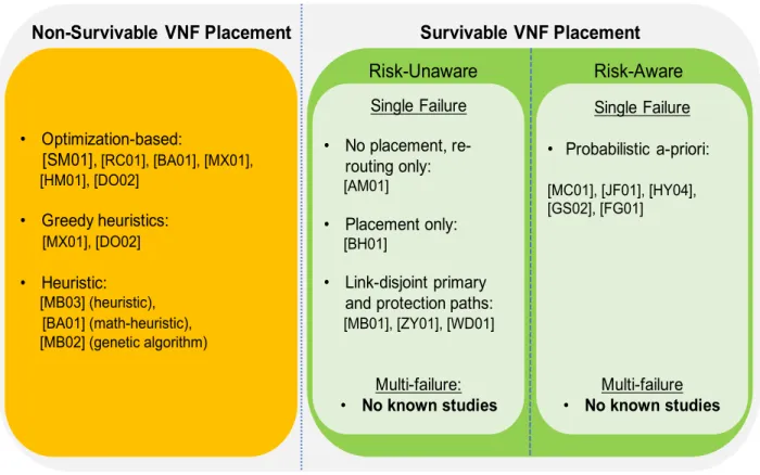
mini-maximize other quantities (such as resource, carried load, energy efficiency, and availabil-ity/reliability), or achieve a tradeoff. Accordinglyl, Figure 2.2 presents a high-level taxonomy of some of the existing VNF placement and/or routing schemes. Those solutions are now surveyed further.
Non-Survivable VNF Placement Survivable VNF Placement
Risk-Unaware Risk-Aware Single Failure • No placement, re-routing only: [AM01] • Placement only: [BH01] • Link-disjoint primary and protection paths:
[MB01], [ZY01], [WD01] Multi-failure: • No known studies Single Failure • Probabilistic a-priori: [MC01], [JF01], [HY04], [GS02], [FG01] Multi-failure • No known studies • Optimization-based: [SM01], [RC01], [BA01], [MX01], [HM01], [DO02] • Greedy heuristics: [MX01], [DO02] • Heuristic: [MB03] (heuristic), [BA01] (math-heuristic), [MB02] (genetic algorithm)
Figure 2.2: A summary of VNF placement and survivability efforts
Foremost, a wide range of studies have looked at VNF placement under regular, i.e., working network conditions, i.e., [SM01], [HM01], [MB03], [BA01], [RC01], [MX01], [MB02], [JC01] and [DO02]. For example, [SM01] presents one of the first studies on VNF placement optimization to maximize the remaining traffic data rate, minimize the number of used network nodes and minimize the total latency over all paths. Moreover, the proposed model
considers some specific constraints, e.g., , an upper-bound number of instances of each VNF, a maximum tolerable latency between endpoints, a pre-defined requests acceptance rate per instance, etc. The solution also develops a chain classifier module to classify flows according
to pre-defined chains and steer traffic according to SFC demands. Furthermore a mixed
integer quadratically constrained program (MIQCP) scheme is also used to provision a VNF
chain in the first stage and embed it into the underlying topology in the second stage. This two-stage approach is necessary due to the linear nature of the adopted scheme. Moreover, the objective function tries to either maximize the transmission data rate, minimize the overall number of assigned nodes or minimize latency. Nevertheless, this scheme does not combine any of these three provisioning objectives.
Meanwhile [RC01] proposes two ILP-based optimization schemes to minimize VNF mapping cost, i.e., uncapacitated and capacited. Specifically, mapping cost is defined as the sum of the setup cost of each function at a specific node and the distance between the nodes. Now whereas the uncapacited scheme assumes that a datacenter has unlimited instance constraints while the capacited scheme, akin to [SM01], assumes a finite and pre-determined number of instances of a VNF. Overall, this solution addresses two key conccerns, i.e., facility
location problem and generalized assignment problem (GAP), governed by the neighboring
distance and setup costs, respectively. However, multiple approximation techniques are
implemented and no routing costs, bandwidth capacity constraints nor traffic engineering constraints are taken into account. The proposed ILP schemes are compared versus a greedy
heuristic algorithm based on performance ratio. The performance ratio is defined by the ratio between the mapping cost and the number of flows supported by a function instance. Results indicate that the former reduces this ratio by at least 60%. Also the authors show that the performance rate significantly increases when function capacity is reduced, showing that as more allocations are necessary, more accurately the ILP scheme has performed. Thus, the authors show that although the location problem is NP-hard, ILP schemes perform better than greedy heuristics as complexity increases.
Furthermore [MB03] presents a heuristic scheme to compose and embed VNF chains (SFCs) and minimize bandwidth utilization in a reasonable amount of time, termed as Co-ordVNF. Specifically, the solution defines a maximum path length parameter to limit the distance between a mapped node and the corresponding substrate nodes, i.e., and achieve some level of flexibility. The CoordVNF scheme is then compared to the MIQCP scheme from [SM01] for maximum path length parameters ranging from 1-5 hops. Overall results show that this method gives significantly faster embedding and service chaining, i.e., on the order of milliseconds vesus order of seconds. This joint performance gain occurs due to the heuristic nature of the scheme, which jointly performs both chaining and embedding in a single stage, i.e., whereas the MIQCP algorithm uses a two-stage approach.
Additionally, [BA01] introduces a mixed integer linear programming (MILP) scheme
to optimally place VNF datacenters over an NFVI and optimally assign requested functions (to VNF datacenters) to build the chains. Specifically, the authors try minimize resources
usage (node and link) and use two different objective functions. Namely, the first technique, termed as TE, defines two separate objective functions, i.e., one to minimize node load and the otther to minimize link load. Meanwhile, the second technique minimizes both node and link loads in the same objective function, termed as TE-NFV.. Additionally, the authors also extend their work in [VM01] and build a heuristic algorithm to handle larger, more realistic operational scenarios. Overall, results show that the TE-NFV scheme reduces the number of VNFs instantiated as compared to the single TE minimization scheme. In addition, VNF setup cost is also 70% lower here. Now these results indicate that the TE scheme gives slightly lower link utilization (about 5% less). However placing VNFs traffic engineering yields substantial setup cost while delay remains the same for both.
Now some studies have also addressed VNF placement for specific solutions, i.e., deploying VNFs to implement a single and specific service. For example [MX01] focuses on heterogeneous NFVI Layer 1 networks and proposes a scheme to minimize NF placement cost in hybrid networks composed of optical and electronic network elements. The goal here is to reduce the optical-to-electronic-to-optical (O-E-O) and
electronic-to-optical-to-electronic (EOE) conversion delay costs by mapping VNFs from the same chain to a reduced
number of datacenters. The problem is modeled as a binary integer linear programming
(BIP) optimization scheme, and a greedy heuristic scheme is also presented to improve applicability (scalability) in more complex scenarios. These two methods are compared with a greedy first-hit heuristic scheme, and results confirm that both of the proposed schemes
drastically reduce the number of required E-O-E and O-E-O conversions (as well as the number of datacenters).
Akin to the above, [MB02] also presents a placement heuristic to minimize the de-ployment cost of a single service in a SDN network, i.e.,deep packet inspection (DPI) service.
Overall, this effort tries to minimize the number of inspection engines deployed and their loads, as well as improve overall efficiency (traffic inspection). Accordingly, a metaheuristic
genetic algorithm (GA) solution is proposed owing to its improved scalability versus linear
solvers. This algorithm uses evolutionary strategies based upon previous results to narrow down the search space, and the authors implement all critical GA steps here, i.e., including random initial population, selection, crossover and mutation. Moreover a greedy heuristic
algorithm is also devised to compute a constrained shortest path (SP) between the two
end-points. Furthermore, several different scenarios are evaluated for two key parameters, i.e., cost of a DPI engine and maximum bandwidth usage per link. Overall results show a clear tradeoff between the number of DPI engines and the network load, e.g., the overall deploy-ment cost can be reduced by up to 58% for a lower DPI cost. Finally Gebert et al [SG01] also present a heuristic algorithm to efficiently place VNFs in a service provider NFVI and optimize cellular coverage for large events.
2.3 NFV Survivability
Overall most VNF placement schemes have focused on objectives such as performance improvement, cost reduction, energy efficiency, traffic engineering, etc. However, VNF
sur-vivability (reliability) is now becoming a major concern given the critical nature of many services. In many cases service providers will still be expected to provide “nines” reliability, regardless of if services are being provisioned over commodity systems or legacy carrier-grade platforms.
Now [BH01] presents a high-level look at VNF resiliency and outlines a range of re-quirements, i.e., failure management, state management/synchronization, VNF migration, and handling larger correlated failures. However this work does not present any specific solution strategies. Instead, only a handful of efforts have addressed survivable VNF place-ment to improve the resiliency of services (mostly for single failures). Specifically, these methodologies have pursued a range of routing, redeployment and pre-provisioned (protec-tion) schemes. A review of the existing VNF survivable schemes is now presented, see also Figure 2.2.
2.3.1 Single Failure Scenarios
Most VNF mapping studies have only addressed survivability concerns for isolated single node and link failures. For example, [AM01] considers the case of a single VNF failure, i.e., datacenter outage, causing a service chain interruption. A extended orchestration architecture is then proposed to dynamically redefine flows and steer (re-route) traffic to establish new paths and reduce downtime. Nevertheless, VNF placement is not considered here. Further considerations for resource limitations and bandwidth constraints are also lacking. As such, this effort only focuses on reactive disaster recovery.
Meanwhile [MB01] proposes another resilient SFC allocation scheme. First, a greedy heuristic algorithm is designed to map thevirtual network functions forwarding graphs
(VNF-FGs) for service chaining requests, thereby yielding resource allocation constraints and VNFs interdependence. Two different protection strategies are then defined, ie.,link resilience and
VNF resilience. The former implements link-disjoint path protection between all neighboring
datacenters, whereas the latter defines alternate datacenters for each NF, i.e., more than one NF per datacenter allowed. A complex (time-consuming) back-tracking scheme is then presented to allocate resources. Specifically, the solution randomly choses a datacenter that is able to instantiate the first NF belonging to a service chain, and then performs a breadth search to find a datacenter capable of instantiating the next function. Resources are then allocated at these datacenters. However, if a datacenter cannot be assigned for a specific NF (according to the service chain specifications), all resources are deallocated and another search is initiated. However, runtime performance is only evaluated for a small topology and a small number of requests, resulting in very few backtracking searches. Furthermore, no resiliency results are presented either.
Meanwhile, the work in [ZY01] presents ajoint topology design and mapping (JTDM)
solution, which uses a heuristic scheme termed asclosed-loop with critical mapping feedback.
This solution builds the network topology (NFVI) and then maps the VNFs in order to
minimize the total bandwidth cost (TBC). In particular, TBC minimization is achieved by
reduce bandwidth load. Furthermore, this solution also incorporates reliability concerns by computing node- and link-disjoint protection service chains. In particular, two protection schemes are considered here, i.e., dedicated and shared [HL01]. Results show a clear tradeoff between reliability and efficiency as expected, with dedicated protection giving higher (lower) reliability (efficiency) than shared protection.
Furthermore, the work in [MC01] takes a slightly different approach and assumes the availability of a-priori probabilistic resource availability levels. An optimization-based MILP scheme and VNF provisioning heuristic are then developed to incorporate these availability levels, i.e., service paths is computed as the product of availability levels of all resources
satisfying the request. This study also assumes that the NFVI is comprised of a large
number of nodes with limited resources distributed across multiple datacenters, and that each node can only host one VNF instance. Overall, the MILP can only handle a small number of demands, whereas the heuristic is capable of fielding more realistic scenarios. Associated results here confirm excessively high computation times with the MILP approach even for smaller testcases. However, although a-priori probabilities are considered here, broader resources constraints, routing costs and traffic engineering concerns are not studied. Akin to the above, [JF01] presents another polynomial-time greedy heuristic scheme to collect the actual temporal availability of physical resources. This information is then used to compute the probabilistic availability of a path and further resolve a primary-protection path pair. Additionally this scheme also tries to increase the acceptance rate of online
re-quests by minimizing physical resources consumption, i.e., map NFs according to availability and resource usage levels. Overall results show that the proposed scheme gives notable bet-ter resilience and resource efficiency versus traditional greedy primary-backup protection schemes (k-shortest paths), e.g., 27% shorter path lengths (link usage).
Finally, [WD01] introduces acost-efficient redundancy algorithm (CERA) heuristic to
efficiently place primary (working) VNFs along with redundant/backup ones. The authors assume that most studies do not consider each NF as part of an interdependent end-to-end service connection, i.e., service chain. In particular, the protection mapping takes into
account the NFVI resources by using a cost-aware importance measure (CIM) scheme to
minimize resource allocation of backup nodes, which tries to guarantee improved performance and therefore higher reliability to the SFC backup paths. Finally, the proposed scheme is compared with two other schemes, i.e., one which tries to minimize backup physical resources costs and another which tries to achieve maximum reliability per iteration. Results are presented for four different metrics, i.e., backup allocation cost, number of physical nodes within a backup path, cost-effective ratio and number of accepted requests. Findings confirm that the CERA scheme outperforms the others for all scenarios. However no failover and disaster-recovery results are presented.
2.3.2 Multi-Failure Scenarios
As noted earlier, most existing VNF provisioning solutions are only designed to handle isolated single failures. As such, these methods will be largely ineffective against large-scale
failure events/stressors, such as natural disasters, power outages, WMD attacks, etc. In fact, there are no known studies on VNF placement and routing within the context of multi-failure disasters. Moreover, the existing body of work on network disaster-recovery has only
focused on point-to-point connections and virtual network (VN) services. Consider some
details here.
In general, disaster events yield a large number of infrastructure node/link failures with a high degree of temporal and spatial correlation. As a result most solutions here define an a-priori set of “risk regions” to model probabilistic disaster events (also termed
as stressors). Namely, here each region has an associated probability as well as failure
sub-graph, i.e., vulnerable subset of datacenter nodes and links. Along these lines, [HL01] presents one of the first studies on “risk-aware” connection routing. Namely, a probabilistic
shared risk link group (p-SRLG) model is introduced to specify a-priori failure risk regions
with conditional node and link failure probabilities. Leveraging this, an advanced integer
non-linear programming (INLP) formulation is then presented to minimize single connection
path and disjoint primary-backup path pair failure risks. Further approximation and linear relaxation techniques are also developed to improve scalability. However, this framework does not incorporate any resource efficiency concerns and hence may lead to longer paths.
To improve resource efficiency, [DO01] proposes a graph-based heuristic method to jointly incorporate both risk and resource usage concerns. In particular, the authors assume that all requests arrive in a dynamic manner and are composed of a source node, destination
node and a required link capacity. Also, a set of probabilistic independent failure events (p-SRLG) are also assumed here, as per [HL01], and associated with a plural number of vul-nerable links. The heuristic scheme analyzes the topology graph and prunes all links with insufficient capacity, creating a secondary topology graph. Adaptive weights are then as-signed to the remaining links according to their respective failure probabilities andk-shorest
paths are computed for the primary source-destination route. Link-disjoint protection paths
are computed for each of these k paths and the path-pair with lowest failure probability
is chosen, characterizing a “risk-aware” weighted link-disjoint path pair definition. Finally, the proposed risk-aware joint protection path and load balancing scheme is compared with three other schemes that do not implement risk-awareness and one that does in regards to failure rate, protection failure rate, bandwidth blocking rate and average route length. Overall, results confirm that the proposed method yields much lower failure rates versus “non-risk-aware” schemes (about 75% less) and yields a minimal increase in average route lengths. Hence this study shows that combining risk-awareness, and traffic engineering can yield substantial gains with regards to survivability.
More recently, follow-on studies have also applied the above-detailed multi-failure “risk-region” models for VN services. For example, [HY04] and [GS02] proposes two heuristic schemes to achieve backup virtual node and link provisioning, i.e., termed as supplemental and incremental. The former computes mappings for each risk region and then combines them using resource sharing on common nodes and links. Meanwhile the latter adds backup
virtual nodes/links as needed to a base mapping in order to protect against each potential risk region. However, these schemes generally yield very high resource inefficiency, and hence further work in [FG01] proposes improved optimization and heuristics-based strategies that work by grouping the failure regions, see related reference for details.
2.4 Open Challenges
Despite the aforementioned contributions, in general there are no known studies on disaster-aware provisioning of NFV-capable infrastructures. This is a major concern since large stressor events can cause multiple failures and resulting widespread services disruption across the whole network, i.e., due to the high degree of virtual function multiplexing being done. In light of the above, there is a pressing need to study NFV provisioning within the context of multi-failure disasters, i.e., network function placement and routing. These solu-tions should incorporate a-priori risk (vulnerability) information and also take into account resource efficiency concerns.
Furthermore, as noted in Section 2.2, most regular VNF mapping schemes perform NF placement under the assumption that datacenters have infinite resources to satisfy all demands. However, under heavy load scenarios and/or post-fault conditions, resource con-straints (scarcity) will likely arise. As a result, there is also a further need to incorporate datacenter node and link bandwidth constraints into the VNF placement and routing pro-cess.
Chapter 3 Joint VNF Placement and Routing with Traffic Engineering 1
As previously mentioned, an increasing number of studies have looked at VNF place-ment and routing to improve service deployplace-ment performance, efficiency and reliability. How-ever most of these efforts have tried to minimize placement costs under the assumption of unlimited network resources to satisfy all requests. As a result, maximizing the number of satisfied NFs is usually secondary. To address more realistic scenarios, this chapter ad-dresses more realistic resource-limited scenarios, e.g., such as those arising during heavy load intervals or after resources failures/outages.
Foremost, an optimization-based scheme is presented for VNF placement and routing, i.e., termed as themulti-objective minimized link load ILP (MLL-ILP) scheme. This solution
pursues several objectives in a weighted manner in order to provide an adaptive solution, i.e., maximize the number of satisfied requests, reduce infrastructure deployment costs, reduce routing costs, and also improve load-balancing, overall this multi-objective approach allows
providers to tailor the outputs to meet their desired needs/tradeoffs. For example if a
datacenter has limited physical resources but sufficient link and routing capacity, deployment costs may be given higher weighting. On the other hand, if link capacities are constrained and path hops and delay times are high, lower routing costs may be more favorable. Also, the
ability to implement load balancing is becoming increasingly important, i.e., as it can benefit service performance in cloud computing and in general, lead to increased revenues. Hence the proposed solutions also incorporate links load levels to improve the VNF provisioning process. Finally, owing to ILP complexity, a further polynomial-time heuristic scheme is also presented to improve scalability, i.e., termed as the multi-objective minimized link load
greedy heuristic (MLL-GR) scheme. These methods are also analyzed and compared for
sample VNF deployment scenarios. Overall this work provides a good basis to develop subsequent disaster-ware VNF schemes.
3.1 Notation Overview
The requisite notation is introduced first. Consider a network infrastructure topology represented by a graphG= (V, E), whereV is the set of nodes andE the set of links. Each link (i, j)∈E has an associated cost cij and capacitybij, which quantifies the cost of using
that link and its maximum bandwidth capacity, respectively. Meanwhile, the subset D⊆V
represents the set of datacenters implementing the NFs, and the complete set of NFs is
denoted by F. Hence a given datacenter d ∈ D only implements a subset of functions
Fd ⊆F. Furthermore, the set of requests is given by the set R. Namely each request r ∈R is characterized by a 4-tuple (srcr, dstr, Fr, br), which denotes the source and destination
nodes of the flow, the set of requested functions Fr ⊆ F, and the required (minimum)
Now it is assumed that the infrastructure has a total of m different VNF resource
types, i.e., resource dimensionality. For example, m=3 can denote processor, storage and
memory. In order to model resource constraints, it is also assumed that a datacenter d ∈
D has a finite amount of resources Wd = {wd,1, wd,2, ..., wd,m}. Hence a datacenter d ∈
D implements a function i ∈ Fd must employ wd,i1, wid,2, ..., wid,m resources. Furthermore, this resource requirement is also datacenter-dependent, which reflects the fact that some datacenters may be designed/specialized to implement certain especific functions. Finally, the setup cost of locating/placing an instance of a function i ∈ Fd at datacenter d is given by ci
d, and an instance of function i at datacenter d can serve up to λid requests. Hence in
order to accommodate more requests, multiple instances of function i must be deployed at
datacenterd, with each consuming additional resources and imposing further setup cost. All of the afformentioned variables are also summarized in Table 3.1, and several other variables are also defined in Section 3.2.
3.2 Multi-Objective Minimized Link Load ILP (MLL-ILP) Model
A detailed MLL-ILP optimization formulation is now presented to achieve several key objectives, i.e., minimize the number of satisfied NFs, minimize deployment cost, minimize routing cost and minimize the maximum overall link load. Consider some requisite ILP-related variable definitions first:
• xi
r,d ∈ {0,1} r ∈ R, i ∈ Fr, d ∈ D|i ∈ Fd: Indicates whether function i ∈ Fr requested by request r∈R is implemented at datacenter d∈D, i.e., binary
Table 3.1: List of variables
Variable Description
V Set of nodes
v Node ∈V
E Set of links
(i, j) Link ∈E connecting nodes i and j
cij Link (i, j) setup cost
bij Link (i, j) bandwidth
D⊆V Set of datacenters
d Datacenter ∈D
F Set of all functions
i Function ∈F
R Set of requests
r Request ∈R
Fr Set of functions requested by request r
br Minimum load required by request r
m Resource dimensionality
• yi
d ∈ Z+ d∈D, i∈ Fd: Represents the number of instances of function i ∈F at
noded∈D
• li,j
r ∈ {0,1} r ∈R,(i, j)∈ E: Indicates whether link (i, j)∈ E is used to route the traffic flow for requestr ∈R, i.e., binary
• 0 ≤ α ≤ 1: Represents the highest overall link usage ratio, i.e., sum of all br
Based upon the above, the MLL-ILP objective function is defined as: max F = w1 X r∈R X i∈Fr X d∈D|i∈Fd xir,d−w2 X d∈D X i∈Fd cidydi −w3 X r∈R X (i,j)∈E cijlrij −αw4 (3.1) subject to: X d∈D xir,d ≤ 1 r ∈R, i∈Fr (3.2) xir,d ≤ yid r ∈R, i∈Fr, d∈D|i∈Fd (3.3) X i∈Fd wid,jydi ≤ wd,j d∈D, r∈R, j ∈ {1,2, ..., m} (3.4) X r∈R xr,di ≤ λidydi d∈D, i∈Fd (3.5) X j:(i,j)∈E lrij − X j:(j,i)∈E ljir = −1;i=dstr, srcr 6=dstr 1;i=srcr, srcr6=dstr 0; otherwise. i∈V, r∈R (3.6) X (d,j)∈E lrdj ≥ xir,d r ∈R, i ∈Fr, d∈D|i∈Fd (3.7) X r∈R li,jr br ≤ αbi,j {i, j} ∈E (3.8)
Overall, the objective function in Eq. 3.1 consists of a series of terms scaled by their respective weighting factors, i.e., w1,w2, w3 and w4. In particular, the first term in Eq. 3.1
represents the total number of requested NFs, whereas the second term is the total cost to setup/deploy NFs at the various datacenters (also called deployment cost). Meanwhile, the third term is the total routing cost, and the fourth term represents the maximum overall link load. Note that the second, third and fourth terms are negative since maximizing a negative term is equivalent to minimizing it [JC02],[JC03]. Furthermore, the setup cost is directly related to the number of satisfied functions and number of instances of each function. Thus the second term (setup cost) depends upon the number of NFs per request and on how many datacenters are used to host these NFs. On the other hand, the third and fourth terms (routing and maximum link load costs) depend upon the number of requests and number of links used. These latter two terms are independent of the number of NFs and NF instances. Now one of the key goals of the MLL-ILP scheme is to avoid link overload or at least minimize link load. Therefore the fourth term in Eq. 3.1 introduces a link load minimization function variable α, which is linked to Eq. 3.8 (detailed later).
Meanwhile, Eqs. 3.2-3.8 represent the model constraints. Namely, Eq. 3.2 ensures that a functionirequested by requestris serviced by at most one datacenterd. Since one of the objectives of the MLL-ILP scheme is to maximize the sum of all variablesxi
r,d (first term of Eq. 3.1), the optimal solution will drive the constraint in Eq. 3.2 to equality. Meanwhile Eq. 3.3 mandates that function i should be located at datacenter d if request r is assigned
to function i at datacenter d. Also, Eq. 3.4 ensures that the aggregate amount of type j
resources used by all functions instantiated at datacenter d should be limited by the total amount of such resources at this datacenter, i.e., wd,j ∈ Wd, j ∈ {1,2, ..., m}. Similarly, Eq.
3.5 states that the total number of requests for function i served by datacenter d should
be bounded by the number of instances of i at d times the capacity λi
d of an instance i. Additionally, Eq. 3.6 represents the necessary flow conservation constraint. Also, Eq. 3.7 guarantees that if a functioniis requested by a request rand is placed at datacenter d, then the demand traffic flow must be routed through that datacenter. Finally, Eq. 3.8 relates to load-balancing and ensures that the sum of all links (i, j) used by a traffic flow (associated with requestr) times the requested loadbrdemanded by requestris bounded by the product of the link capacity bi,j timesα. As a result, traffic flows are associated with links that have reduced load profiles (higher available capacity).
3.3 MLL-ILP Complexity
Since the MLL-ILP objective function and constraints are linear and all variables are either integer or binary, the optimization problem is NP-hard [TC01]. Hence the complexity of this model can be judged by the total number of variables that the scheme utilizes. In particular, the total number of variables xir,d, ydi and lri,j (Eqs. ??-??) is upper-bounded by
|R||F||D|,|F||D|and|R||E|, respectively.Based upon this, the upper-bounds for the number of constraints, Eqs. 3.2-3.5, are also |R||F|, |R||F||D|, |R||D||Wd| and |F||D|, respectively.
Meanwhile, the upper-bounds for the number of constraints in Eqs. 3.6 and 3.7 are
|V||R| and |R||F||D|. Finally, the upper-bound on the number of constraints in Eq. 3.8 is
|V||R|+ 1.
From the above, the upper-bound for the total number of variables is dominated by the product|R||F||D|. Now in general, it is very difficult to pre-specify limits for the number of requests or number of functions to ensure ILP convergence. However for small-to-medium sized network topologies, the proposed ILP can be solved in a reasonable amount of time, i.e., less than a few hundred nodes.
3.4 MLL-GR Heuristic
Although the MLL-ILP approach provides an optimal VNF placement solution, its run-time performance can be a concern in complex scenarios with increased variable costs and high resource dimensionality. As a result, heuristic schemes can be developed to build more scalable, albeit non-optimal, solutions. Along these lines, a greedy graph-based heuris-tic algorithm is also presented to solve the NF placement problem in larger networks, as shown in Figure 3.1. Overall, this algorithm implements a two-stage solution. Namely, given a graph and input parameters (akin to MLL-ILP; source, destination, set of NFs and min-imum link capacity), the algorithm returns the VNF mappings, associated paths, number of function instances in each datacenter and the highest link load. Before presenting this scheme, however, some further variable definitions are introduced here as follows.
• K: Number of datacenters that satisfies function i requested by request r
• dk: Datacenter that satisfy function i requested by request r • yi
dk: Total number of instances of function iin datacenter dk
• λid
k: Maximum number of clients per instance of function i in datacenter dk
• D(r): Set of datacenters serving request r
• C(r): Subset of D(r) that tracks the datacenters serving request r connected to their respective neighbors within the source-destination path
Overall, the first stage in Figure 3.1 (lines 4-15) focuses on NF placement at specific datacenters to reduce deployment cost. Namely, for each function i requested byr ∈R, the algorithm selects the datacenter dk that implements iwith the lowest setup cost and at the same time has sufficient resources to host upcoming requests (line 8). Once a NF is placed,
the resources at datacenter dk are updated accordingly. Namely if there is an instance of
NF i at datacenter dk with enough instance capacity to satisfy request r, the remaining
capacity is simply decremented by 1. Otherwise, another instance of NF i is created at cost
ci
dk, where each newly-created instance can serve λ
i
dk −1 requests. Hence either way, the
available resource levels at datacenter dk, i.e., wdk,i (1≤ j ≤ m) are reduced by w
i
dk,j (line
9, Figure 3.1). Note that serving a request does not incur any additional cost, i.e., only new instantiations of NF i do. Additionally, for each new instance of NF i, the total number of instances at datacenter yi
dk is also incremented by 1 (line 10, Figure 3.1) and x
i
r,dk is set to
To conclude NF placement (first stage), datacenterdk is also added to a set variable,
D(r), which tracks the subset of datacenters serving request r.
Meanwhile, the second stage in Figure 3.1 (lines 14-27) computes the shortest path between the source srcr and destinationdstr, that passes through all datacentersdk ∈D(r). Initially, the algorithm starts by connecting the source node srcr to the first datacenter d1
in D(r). In particular, this connection route is computed using the constrained Dijkstra’s shortest path algorithm (line 20, Figure 3.1) and only considers links in G(V, E) with suffi-cient capacity to support the requestedbr. The routing cost here is defined by the sum of the setup cost of all links associated with a traffic flow and each respective link capacity/request load ratio, as follow:
X
(i,j)∈E
cij +br/bij (3.9)
All variablesli,j
r along the path are then set to 1 (line 21, Figure 3.1), and datacenter
d1 is also added (line 22, Figure 3.1) to another set variable C(r). Namely, this subset
tracks the datacenters serving requestrthat have already been connected to their respective
neighbors within the srcr and dstr path. Now if there is another datacenter j ∈ D in the
path between the source and destination, it is also added toC(r) (line 23, Figure 3.1), i.e., in order to avoid duplicated/overlapped routes for datacenters yet to be analyzed in upcoming
iterations. Before returning to the beginning of the loop, the temporary src variable is
The algorithm (second stage) then loops to process the next datacenter serving the request. Again, a shortest-path is computed between the previous destination and the fol-lowing datacenterdk ∈D(r), i.e., in the second iteration a path is computed betweend1 and
d2. In the two final steps, a shortest path is computed between the last datacenter and the
destinationdst(line 30), and all links li,j
r within that traffic flow are set to 1 (line 27). Now, note that the greedy heuristic scheme is not an optimization algorithm, which means that it does not loop searching for lower solutions. It is a one-time iteration method, and by the end of the only iteration, costs are calculated for each and all requests.
3.5 MLL-GR Complexity
Consider the computational complexity of the MLL-GR heuristic. Conceptually, this algorithm tries to lower runtime overhead by finding the first acceptable solution. In par-ticular, the first stage selects a datacenter, d, that can implement function i ∈ Fr with the lowest cost (line 8, Figure 3.1). Note that NF placement here is done in a serialized manner, i.e., each NF is placed independent of requirements of the following NF. However, the second stage poses higher complexity as it runs the constrained Dijkstra shortest-path algorithm within a double loop. In particular, this stage is invoked a total of |R||D|times, D(r)≤D. Now assuming a binary heap Dijkstra implementation complexity of O(|E|log|V|) [TC01], the overall complexity of the MLL-GR heuristic scheme is dominated by the second stage and is given by O(|R||D||E|log|D|).
1: INPUT: G(V, E), cij∀(i, j)∈E, R, F, D
2: OUTPUT: xir,d, yid, lijr values
3: setxir,d= 0, ydi = 0, lijr = 0 for all r ∈R, i∈Fr, d∈D,(i, j)∈E {BEGIN FIRST STAGE}
4: forall r∈R
5: D(r) ={}
6: k= 1
7: for all i∈Fr
8: dk = datacenter that implementsiat minimum cost and has enough resources to serve an
additional request 9: update resources of dk 10: updateydi k 11: set xir,d k = 1 12: D(r) =D(r)∪dk 13: k=k+ 1
{END FIRST STAGE} {BEGIN SECOND STAGE}
14: forall r∈R 15: src=srcr 16: C(r) ={src} 17: for k= 1 to |D(r)| 18: dst=dk 19: if dk∈/C(r) 20: SP =constrained Dijkstra(src, dst) 21: setlijr = 1 for all link (i, j)∈SP
22: C(r) =C(r)∪dk
23: C(r)∪j, for all datacenterj∈SP, j∈D(r) 24: src=dst
25: dst=dstr
26: SP =constrained Dijkstra(src, dst) 27: set lijr = 1 for all (i, j)∈SP
{END SECOND STAGE}
28: return NF mappings, NF instances in each datacenter, links within a path
Figure 3.2: NSF network topology.
3.6 Performance Evaluation
The proposed VNF routing and placement solutions (MLL-ILP and MLL-GR) are now analyzed for a sample deployment scenario. Specifically, the optimization model is
solved using the lpsolve solver API running on a 64-bit Windows machine with an Intel(R)
Core(TM) i5 CPU (1.4GHz) and 2 gigabytes of RAM. In order to evaluate the proposed NF placement schemes, a sample 16 node/25-link network topology is chosen here, as shown in Figure 3.2. This setup reflects a large backbone facility, and it is further assumed that each node is also a datacenter i.e., in addition to providing routing/switching capabilities (|V|=|D|=16). The datacenter resource dimensionality is also set to m=3, i.e., representing processor, memory and storage.
Overall, three different testcase scenarios are defined and tested here. In particular, the first testcase performs sensitivity analysis in order to fine tune the various weighting fac-tors in the objective function, Eq. 3.1 (for use in the second and third testcases). Meanwhile,
Table 3.2: Testcases parameters
Parameter First Testcase Second Testcase Third Testcase
Link 1,000 1,000 10,000 Resources (wd,1,wd,2,wd,3) 500 500 5,000 Weight w1 1,000 Weights w2 1/10 1 1 Weights w3 10/1 1 1 Weights w4 10/1000 1,000 1,000 Function set f0,f1,f2,f3,f4 Required Resources (wi d,j) 30≤wd,ji ≤70
Function Setup Cost 50
Instance Capacity 2
Link Setup Cost 20
the second and third testcases are used to evaluate the proposed schemes for varying physical and links resource levels. Specifically, the second testcase is termed as an under-resourced
scenario and uses lower values for both datacenter and connectivity resources. Meanwhile the third testcase is termed as a highly-resourced scenario and emulates settings with higher
resources levels. In light of the above, all testcases have three different datacenter resources levels, as shown in Table 3.2, i.e., Wd={wd,1, wd,2, wd,3}. Namely, the first and second
test-cases use values of wd,1=wd,2=wd,3=500 units, respectively. Additionally, all link capacities
are set to 1,000 units here, i.e.,bi,j ≤1,000 for all (i, j)∈E. Meanwhile, the third testcase sets all datacenter resource levels to 5,000 units. The corresponding link capacity is also increased to 10,000 units here. The various other test parameters are equivalent across all testcases. Namely, the function set F is limited to five types, i.e., F={f0, f1, ..., f4} and it
amount of resources wd,ji needed to implement a function i∈Fd is also uniformly distributed
between 30≤ wi
d,j ≤70 units. Meanwhile the setup cost of placing an instance of function
i∈Fd at datacenter d∈D is set to cid=50, and the instance capacity λid of a function i at datacenter d is set to 2. Finally, each request r requires four NFs, namely Fr is randomly selected from F (Fr⊆F).
3.6.1 Weighting Factors Selection (First Testcase)
Proper selection of weighting factors in the objective function, Eq. 3.1, is crucial for effective NF placement and routing. As a result the first testcase evaluates the im-pact/sensitivity of these values in maximizing the number of satisfied requests (w1) and
minimizing the deployment, routing costs and link load costs (w2, w3 and w4). Now recall
that the first term in Eq. 3.1 represents the number of satisfied NFs, which is typically a small value. Also the other terms represent costs with negative values (minimization). Hence it is imperative to assign a relatively higher value to w1. Meanwhile, the deployment cost
(second term) is related to the number of satisfied NFs i and their respective costs. Hence deploying multiple NFs at the same datacenter reduces the deployment cost of each instance capacity, λi
d, at a datacenter. On the other hand, the routing cost (third term) and the link load cost (fourth term) are associated with the number of links used for each traffic flow. Although both of these values are related to the number of hops, minimizing link load cost can result in longer paths. Clearly, this trade-off needs to be analyzed further.
In general, deployment and routing costs are associated with a large number of vari-ables in the mLL-ILP model, i.e., up to|D||F|and|R||E|, respectively. Hence increasing one of the associated (minimization) terms in Eq. 3.1 can lower the overall cost. However this approach may also increase the other costs. Accordingly, Figure 3.3(a) and Figure 3.3(b) show the trade-off between deployment and routing costs. Namely, Figure 3.3(a) compares the deployment cost for different weight values of w2 and w3. Overall, a larger routing cost
weight (w3=10) gives increased deployment costs, whereas a larger deployment cost weight
(w2=10) results in lower deployment cost. Meanwhile, Figure 3.3(b) also indicates that
assigning higher weights to routing cost reduces this component at the expense of higher deployment cost.
Finally, consider the link load minimization term (fourth term) in Eq. 3.1. This term only has a single fractional valueα, which is computed as the ratio of between all requests br using a specific link (i, j)∈E and its corresponding link capacity bi,j. Note that the fourth term is directly correlated with the third term, i.e., routing cost, since both use variableslijd
and br. Hence w4 can be used as a balancing factor to select between one of the other two
minimization terms, i.e., deployment or routing cost. Namely, minimizing αreduces routing
cost and increases deployment cost. Furthermore, increasing w4 decreases routing cost and
increases deployment cost. Finally,w4 also provides increased sensitivity due to its fractional
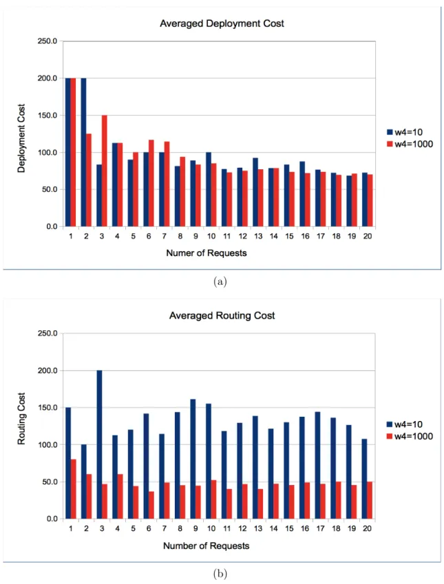
Now in order to demonstrate the effect of varying w4, an empirical methodology
is deployed here using two different values, i.e., w4=10 and w4=1,000. Specifically, tests
are performed for a varying number of input batch requests, ranging from 1 to 20 (20 placement solutions) with the remaining weights set to w1=1,000, w2=1 and w3=1. Here,
Figure 3.4(a) compares the average deployment cost for both values of w4, i.e., computed as
deployment cost/number of requests. Overall, these results show that the two costs are very similar. However, the average routing costs shown in Figure 3.4(b) show notable differences. Namely, the w4=10 value gives anywhere from 2 to 4 times higher values than w4=1,000,
i.e., computed as routing cost/number of requests.
Overall, the maximum link load variable α can be used to modify NF placements
according to service provider needs. For example, some may prefer placing NFs to reduce deployment costs due to physical datacenter resources limitations. Meanwhile others may prefer to reduce routing cost due to network link transmission constraints, i.e., lower link capacity, increased delays, etc. Based upon the above sensitivity analysis, the respective weighting factors are set to w1=w4=1,000 and w2=w3=1 in the remaining testcases.
3.7 Under-Resourced Scenarios (Second Testcase)
The second testcase considers under-resourced settings and assumes the same set of input parameters defined in Section 3.6. In particular, up to 30 arriving batch requests are processed here to measure the impact of reduced datacenter and link level resources, as shown in Table 3.2. For comparison purposes, “standardized” non-load-balancing versions of
the respective optimization and heuristic schemes (i.e., MLL-IP and MLL-GR) are devised
and also tested here. In particular, the joint routing and placement ILP (JRP-ILP) method
removes the fourth term in the objection function, i.e., w4α in Eq. 3.1. Similarly, the joint routing and placement greedy heuristic (JRP-GR) scheme implements the algorithm shown
in Figure 3.1 but removes the fourth term w4α.
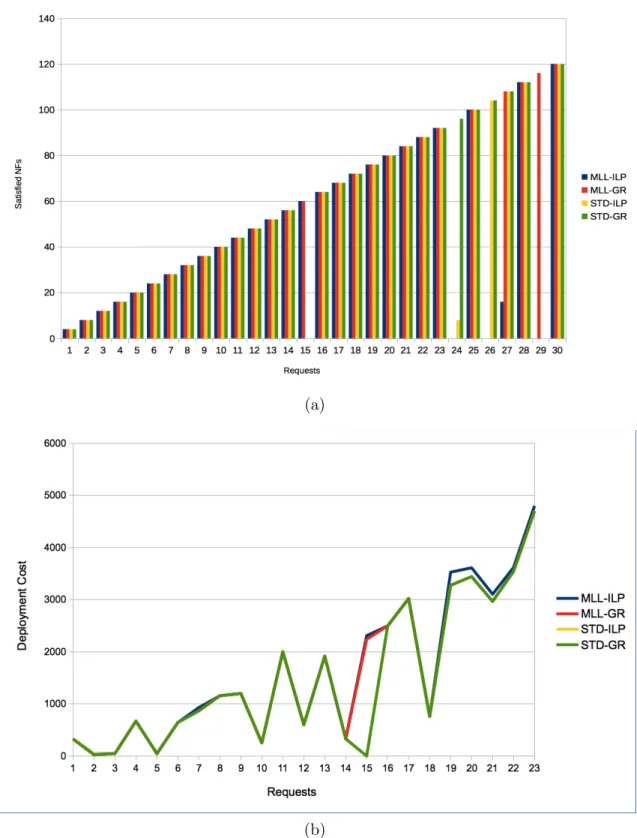
Overall Figure 3.5(a) plots the number of satisfied NFs for the second testcase and shows that all four schemes begin to drop demands after 24 requests, i.e., due to resource limitations. Hence in the subsequent plots, results are only shown for up to 23 requests. However, note that both the JRP-ILP and JRP-GR schemes (yellow and green lines) also fail to satisfy the 15threquest due to their inability to balance link loads. In particular, these methods yield higher link congestion, leading to overload and rate blocking on selected links. Meanwhile, Figure 3.5(b) also compares the deployment cost for this testcase. Clearly, all schemes yield very similar values, albeit the JRP-ILP and JRP-GR methods yield zero cost for request 15 since they cannot satisfy the requested NFs here. Furthermore, the MLL-ILP (blue) and JRP-MLL-ILP (yellow) schemes also exhibit negligibly higher deployment cost (by about 5%) for request 19 and beyond. However, the routing costs are shown in Figure 3.6(a) and clearly show a huge separation between the optimized ILP models (blue and yellow) and greedy heuristic schemes (red and green). Namely, the latter methods yield about twice as much routing costs than their respective optimization-based counterparts. Now in general, the routing cost is directly related to the number of links used to route the connections.