Deriving Component Interfaces after a Restructuring of
a Legacy System
Abderrahmane Seriai, Salah Sadou, Houari Sahraoui, Salma Hamza
To cite this version:
Abderrahmane Seriai, Salah Sadou, Houari Sahraoui, Salma Hamza.
Deriving
Compo-nent Interfaces after a Restructuring of a Legacy System.
Working IEEE/IFIP
Confer-ence on Software Architecture (WICSA), Apr 2014, Sydney, Australia.
pp.31 - 40, 2014,
<
10.1109/WICSA.2014.27
>
.
<
hal-01102164
>
HAL Id: hal-01102164
https://hal.archives-ouvertes.fr/hal-01102164
Submitted on 12 Jan 2015
HAL
is a multi-disciplinary open access
archive for the deposit and dissemination of
sci-entific research documents, whether they are
pub-lished or not.
The documents may come from
teaching and research institutions in France or
abroad, or from public or private research centers.
L’archive ouverte pluridisciplinaire
HAL
, est
destin´
ee au d´
epˆ
ot et `
a la diffusion de documents
scientifiques de niveau recherche, publi´
es ou non,
´
emanant des ´
etablissements d’enseignement et de
recherche fran¸
cais ou ´
etrangers, des laboratoires
publics ou priv´
es.
Deriving Component Interfaces After a Restructuring
of a Legacy System
Abderrahmane Seriai
IRISA
Universit´e de Bretagne Sud Vannes, France
Salah Sadou
IRISA
Universit´e de Bretagne Sud Vannes, France [email protected]
Houari Sahraoui
DIRO Universit´e de Montr´eal Montreal, Canada [email protected]Salma Hamza
IRISAUniversit´e de Bretagne Sud Vannes, France [email protected]
Abstract—Although there are contributions on component-oriented languages, components are mostly implemented using object-oriented (OO) languages. In this perspective, a component corresponds to a set of classes that work together to provide one or more services. Services are grouped together in interfaces that are each implemented by a class. Thus, dependencies between components are defined using the semantic of the enclosed classes, which is mostly structural. This makes it difficult to understand an architecture described with such links. Indeed, at an architectural level dependencies between components must represent functional aspects.
This problem is worse, when the components are obtained by re-engineering of legacy OO systems. Indeed, in this case the obtained components are mainly based on the consistency of the grouping logic. So, in this paper we propose an approach to identify the interfaces of a component according to its interactions with the other components. To this end, we use formal concept analysis. The evaluation of the proposed approach via an empirical study showed that the identified interfaces overall correspond to the different functional aspects of the components. Keywords—Object-Oriented Application, Component-Based Ar-chitecture, Interfaces Identification, FCA (Formal Concept Analy-sis)
I. INTRODUCTION
Nowadays, components are most often built using object-oriented technology. This is normal as, usually, new program-ming paradigms are defined using previous ones. That was the case for classes that are built on the procedural paradigm.
Classes are designed to hide their implementation (pro-cedural details), i.e., encapsulation principle. This is also true for components that need to hide their implementation (details of contained classes). Components must expose only their provided and required interfaces. The organization of these interfaces should not reflect the implementation details of their component. They must be organized according to the component’s business logic independently of classes that actually provide services exposed by the interfaces.
This problem appears when building components from scratch. However, it is more blatant during automatic restruc-turing of an object-oriented application into a component-based application. Indeed, in this case the approach of ex-traction of components is mainly based on the consistency of the groups of classes. In addition, the obtained components often have a large number of classes, which complicates the
identification of their interfaces. There are two advantages of this type of restructuring: i) allowing a better understanding of the system to achieve its current maintenance thanks to its extracted architectural representation based on the component paradigm. ii) facilitating its future maintenance by its reim-plementation within a component technology while relying on its architectural representation. Most of the work on the extraction of components from object-oriented applications consider components as clusters of classes with a set of provided methods and a set of required methods [12], [13], [19], [32].
To the best of our knowledge, one of the most important works that projects the extracted components on a concrete component model used an extracted component oriented archi-tecture [1]. In this work, the organization of the interfaces was achieved through a direct mapping to the component’s classes. Although this projection is an improvement with respect to the existing work, it still reveals the details of the component implementation. The disadvantage is that if the definition of component interfaces is strongly influenced by structural as-pects, coming from the object approach (component’s internal classes), it complicates the understanding of the relationships between components. Indeed, component interfaces should represent its functional aspects and its relationships with the other components should imply only that.
In this paper, we propose to consider the problem of orga-nizing the interfaces of a component starting from its classes and all their exposed methods. Thus, our starting point is the result obtained by the majority of the works on component extraction from object-oriented applications. More concretely, we view interface organization as a clustering problem based on dependencies between the exposed methods (services) and components that use them. Formal-concept analysis techniques are used to perform the clustering. The idea behind this is that when a component uses another, it means that it needs one or more specific aspects from the latter. The analysis of all interactions of a component allows us to define its various exposed aspects. Each aspect is represented by a subset of the exposed methods and will be implemented as an interface of the component. This applies to the provided interfaces. Similarly, in a context where components are extracted from the same application, the required interfaces of a component are defined according to interfaces provided by the other components that it uses.
in-troduces some definitions, highlights the component extraction issues, the interfaces identification and gives an overview of Formal Concept Analysis (FCA). The interfaces identification approach is presented and illustrated with an example in section III. Our approach is evaluated and discussed through an empirical study in Section IV. Concluding remarks are given in Section VI.
II. BACKGROUND ANDRELATEDWORK
The goal of our work is to organize the interfaces of the extracted components, from an object oriented application, according to their interactions. The perspective is to produce an architecture with more meaningful bindings, which simplifies the system understanding. This step is very important for the projection of the produced architecture into a concrete com-ponent model while avoiding object oriented design influence. This section gives the necessary background, including the related work, to the presentation of our contribution.
A. Architecture Extraction
Software architecture plays an important role in at least six aspects of software development: understanding, reuse, construction, evolution, analysis and management [10]. Many approaches and techniques were proposed in the literature to support software architecture recovery [12], [13], [19], [32], [8], and often the problem is redefined as a software clustering problem. The software clustering problem consists of finding a good partition of software modules based on various criteria, in particular, the dependencies among these modules [18]. Dependencies are extracted by static analysis, dynamic analysis, or using a combination of both (so-called hybrid approaches).
Among the approaches that use static analysis, Pourhaji Kazem et al. [21] proposed a genetic algorithm for clustering based on weighted module dependency graph. Saeed et al. [24] used the Rigi tool to extract the function dependency graph and presented a new clustering algorithm called the “combined” algorithm to implement software architecture recovery. Man-coridis et al. [17] extracted the file dependency graph from the source code and used a clustering algorithm based on a genetic algorithm.
With regard to approaches that use dynamic analysis, Yan et al. [33] described a technique that uses run time observations about an executing system to construct an architectural view of the system. In a previous work, we proposed an approach to restructure an object-oriented application into a component-oriented one [3]. This approach is based on dynamic calls,
i.e. actual calls at runtime with use cases, to determine the dependencies between classes. These dependencies are then used by a genetic algorithm to derive groups of classes representing components
For hybrid approaches, Richner et al. [22] presented an environment supporting the generation of tailorable views of object-oriented systems from both static and dynamic infor-mation. Claudio Riva et al. [23] proposed a technique for combining the analysis of static and dynamic architectural information to support the task of architecture reconstruction
B. Interface Identification
We find that the reverse engineering research commu-nity has been actively investigating techniques to decompose (partition) the structure of software systems into subsystems (clusters) [26], [5], [20], [15], [29], [4], but regrettably the most part of researchers limited themselves to that, ignoring the problem of provided/required interfaces identification. In the context of restructuring an application,required interfaces
of a component, i.e.,what the environment should provide in terms of services to the considered component, are defined so that they match the provided interfaces by the used components,i.e.,what the component should provide in terms of services to its clients. For this reason, the first step to perform is to define the provided interfaces for all components. Among the few studies that have addressed the problem of interface identification, we can cite the work by Chouambe et al. [6]. The starting point in their approach is a list of classes and interfaces (in the sense of OO programming) and the relationships between each other in the analysed software system. They create two lists L1 and L2 of tuples consisting each of a class and an interface. Tuples of L1
consist of the implementation relationship between classes and interfaces, whereas tuples of L2 represent the used-by relationship between classes and interfaces. Thereafter, they consider classes as components and the interfaces implemented in the analysed system as the provided interfaces of the extracted components and the interfaces used as the required ones. Although the idea is interesting, it is completely based on the OO application logic. Consequently, to implement/package the identified components according to a concrete component model, one must first identify the provided interfaces and then implement them in the application language.
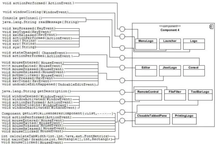
A trivial solution would be to create a unique interface offering all the exposed methods (services). This solution is, however, undesirable since it requires the other components to use a single interface regardless of the services they need, which implies that components provide only one aspect, which is unlikely. An alternative solution was proposed in [1]. In this work, exposed methods are grouped by their classes,i.e.,one interface per contained class, if it holds methods used by the other components. Figures 1 shows the result of this strategy for an extracted component.
Although this solution offers more interfaces to be used by the other components, it violates some component ori-ented principles. Indeed, the interface definition is based on the internal structure of the components. Thus, it violates the encapsulation principle (black box) of the component paradigm. To be consistent with this paradigm, the organization of interfaces should be based on the functional aspect of the component and not on its concrete implementation.
C. Formal Concept Analysis (FCA)
We consider interface organization as a clustering problem. In this perspective, we use formal concept analysis (FCA) [9] to group exposed methods into interfaces. FCA is a classifica-tion technique that is based on the lattice theory.
Much works have already used formal FCA for soft-ware clustering problems. For example, in legacy system re-engineering, FCA was used to identify objects in procedural
Fig. 1. Organization of the interfaces based on contained classes
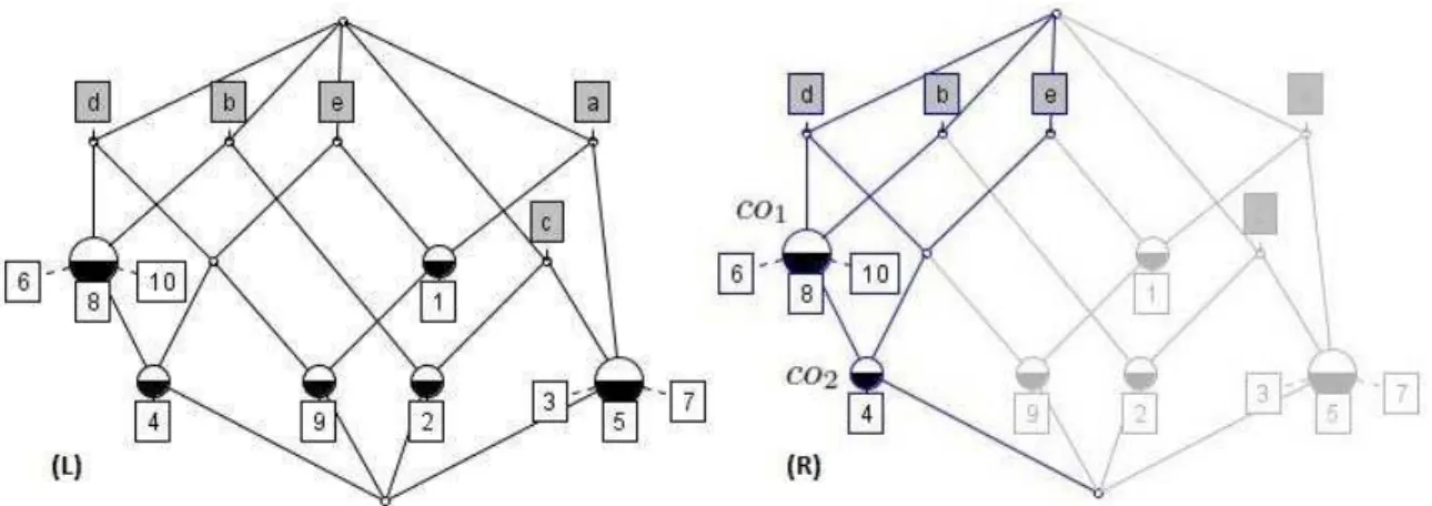
code [25], [30]. FCA was also used for restructuring existing OO code [7], [27], refactoring existing code toward aspect-oriented [28], [31] or component-aspect-oriented [16], [2] paradigms. FCA allows the identification of groups of elements having common attributes. FCA considers contexts defined with the triple (O, At, As). O is the set of elements (in our case the calling components), At the set of attributes (in our case the called methods) and As the relation that associates elements to attributes. As is generally represented by an association matrix, with the elements as rows and attributes as columns. An example of a formal context is shown in Table I, with a set of elements O = {1,2,3,4,5,6,7,8,9,10} and a set of attributes At={a, b, c, d, e}. In this table, element 1, for example, has the attributes aande.
TABLE I. AFORMAL CONTEXT FOR THE ELEMENTSOAND THE ATTRIBUTESAt. a b c d e 1 × × 2 × × 3 × × 4 × × × 5 × × 6 × × 7 × × 8 × × 9 × × × 10 × ×
FCA extracts the set of all formal concepts from a formal
context. A formal concept is a maximal set of elements (called extent) sharing a maximal set of attributes (called intent). We can express the formal concept as a pair of corresponding sets (E, I)such that:
Extent E ={e ∈O | ∀i ∈I,(e, i) ∈As} (covered objects) and
Intent I={i∈At| ∀e∈E,(e, i)∈As} (shared attributes).
For the example of Table I, co1 = ({4,6,8,10},{b, d})
is a formal concept because the objects 4,6,8, and 10share exactly the attributesbandd, and conversely. On the contrary,
({6},{b, d}) is not a formal concept as it is subsumed by
co1 (subset of the extent and the same intent). In addition to the set of all formal concepts, it is possible to define an inheritance relationship between concepts. The conceptco1 is more general than the concept co2 if the extent of co2 is a subset of the one of co1, and the intent ofco2is a superset of the one ofco1. Formal concepts and their relationships form a concept lattice. The concept lattice obtained from the context of Table I is illustrated in Figure 2 (left).
In Figure 2 (right), we can see that the concept
co2 = ({4}{b, d, e}) is a sub-concept of concept co1 = ({4,6,8,10},{b, d}) because it inherits the attributes b and
Fig. 2. Example of formal concept lattice (left) and a focus on conceptco2(right).
III. INTERFACEIDENTIFICATIONAPPROACH
Conceptually, as depicted in Figure 3, a component is intended to implement a high-level feature (e.g., image pro-cessing). This feature is generally offered through a set of facets (e.g.,create images, convert images, merge and overlay images, etc). For efficient use of a component and to give meaning to its bindings in an architecture, the various aspects of a component must be represented by separate interfaces. When components are derived from an OO application, each component correspond to a set of classes. The services offered by components are the exposed methods of their classes. However, the notion of interface is not explicitly defined. To create interfaces, one should identify component facets from the code.
Fig. 3. Aspects involved in interface definition
To identify the various functional facets of a component, we rely on the way the other components use it. Indeed, for a given component, the subset of features, which are used by another component, partially highlights one or more of its functional aspects. The analysis of all the facets of a component, which are highlighted by its use by all the other components of the application, allows us to identify a coherent set of interfaces (facets) that the component should expose. Thus, we can treat the problem of interface organization as a clustering problem based on dependencies between compo-nents.
A dependency is defined by the pair (calling component,
called service). Using this definition of dependencies, we use a formal concept analysis to classify services according to the components that use them.
Figure 4 gives an overview of the proposed approach for the identification of the component’s interfaces. The identification is the result of four steps: the first three steps are performed automatically while the last one needs a collaboration with the designer.
In the following sections, we detail the steps of our ap-proach through an illustrative example. This example concerns the Logo application, which was already used to illustrate our approach for component extraction [3]. The identified components for Logo are as follow:
• Component 1: The Language Parser component is used to read the logo code, to interpret it according to the Logo grammar, and to launch appropriate java treatments.
• Component 2: The Evaluator that receives a list of instructions to evaluate it in the current lexical envi-ronment.
• Component 3: The Graphical Display component dis-plays the results of a Logo program.
• Component 4 The Graphical User Interface (GUI) component represents the graphical interface through which beginner programmers interact with the appli-cation.
As can be understood through the definition of the above components, the Logo application is a programming learning tool with a graphical display of results.
A. Formal Context Construction and Classification
For each component we build a formal context. This context summarizes the dependencies of the other components with the current one. In our approach, we consider that these dependencies already exist and have been determined during the component extraction process. In the case of redefining
Fig. 4. An overview of the component’s interface identification approach
the components’ interfaces of an already existing component-based application, it is possible to have these dependencies by a simple analysis of its source code.
The formal context is created as a matrix with lines corresponding to the calling components and columns corre-sponding to the services called on the component.
Table II shows a part of the formal context associated to the Logo’s Language Parser component.
TABLE II. FORMALCONTEXT FOR THELANGUAGEPARSER
COMPONENT
m1 m2 m3 m4 m5 m6 C1
C2 × × × ×
C4 × × × ×
The component’s methods are referred in the table by their number and the correspondence is given in figure 5. Thus, this component is used by only two components (Graphical Display and Evaluator components). In fact, the GUI component never directly accesses to the Language Parser component.
For each formal context corresponding to a called compo-nent, the FCA classifier module derives a concept lattice in which services are grouped according to the calling compo-nents. Lattice construction follows the principles described in Section II-C.
The lattices corresponding to the matrix of Table IIis shown in Figure 5.
Fig. 5. The concept lattices for the Language Parser component
In the constructed lattices only concepts that hold services (circles with a coloured top) are interesting. If a concept holds a component (bottom coloured) it is even more interesting because it shows the aspect highlighted by that component.
B. Lattice Interpretation
The aim of the Lattice Interpreter stage is to suggest interfaces for the called component based on its corresponding lattice. Some of concepts may be considered as interfaces thanks to their use by a single component (lower level of the lattice) while others are consequence of a combination of components (upper levels of the lattice).
In the example of Figure 5, three interfaces may be taken into account for the Language Parser component. This may seem obvious because the Logo example was deliberately chosen for its small number of components in order to simplify the explanation of our approach. But when the application contains a large number of components, which is for example the case of applications taken for the empirical study (see Section IV), the number of concepts (interfaces) in a lattice can be very large. So, it is not reasonable to let the designer solely responsible for determining the optimal combination of concepts.
Thus, the Interpretation stage aims to offer a combination of concepts that satisfies the following properties:
1) It must contain all the services exposed by the com-ponent.
2) Each service belongs to only one concept: this is dictated by the clustering problem, but it means that a method of a class can participate in only one aspect of the component that contains it.
3) the number of concepts should not exceed a limit set by the designer. Indeed, the number of interfaces per component is one of the quality properties that each company defines according to its experience. 4) Among the combinations of concepts which satisfy
the above conditions, the proposed solution must optimize the objective function defined below.
dev(C) =
P
i∈CidevI(i)
|Ci|
with Ci={interf aces of C} (1)
devI(I) =
P
c∈I udevIbyC(I, c)
|Iu|
with Iu={components using I} (2)
devIbyC(I, C) =
P
m∈IN otU sedBy(m, C)
|I|
with I ={methods in the interf ace} (3)
N otU sedBy(m, C) =
0 if m is used by C
1 otherwise (4)
The objective function measures the quality of the selected combination of concepts with respect to aspects. In our ap-proach, the aspects of a component are determined by the components that use it. Thus, the optimum would be to have an aspect (interface) per user component. As the objective function measures the deviation, then the best solution is the one that gives the minimum result. The deviation for a component corresponds to an average of the deviations of all its interfaces (equ. 1). The deviation for an interface is the average of its deviations with all components that use it (equ. 2). The deviation of an interface with respect of a user component is the portion of its methods that are not used by the latter (equ. 3).
Having the lattice corresponding to a component and the objective function, it becomes possible to propose the com-bination of concepts (component’s interfaces) that meets all the conditions mentioned above. The selection of the concepts representing the solution is done through the following steps: 1) In the first step are selected only concepts that are associated with user components. The maximum number of interfaces (rule 3) can be exceeded and the problem will be solved when negotiating with the designer (see next subsection).
2) If the specified number of interfaces is not reached, then the lattice is visited level by level, from the bottom, and are selected concepts that contain the largest number of methods. This process is stopped when the specified number of interfaces is reached. 3) This step is useful only if after reaching the fixed
number of interfaces there are still non selected concepts while they contain methods. Each of these concepts will be completely fused with an already selected concept. The aim is to avoid break up an already identified concept.
For the last step, the search for non selected concepts is done by browsing the lattice, level by level, from the top. Thus, we first consider the most constraining concepts. For each, we
determine the set of its sub-concepts that are already selected. We consider the fusion of the concerned concept with each concept of that set and we measure the objective function at the interface level (equ. 2). The fusion which obtains the best score will be realized.
Our approach promotes the identification of concepts against a strict compliance with the limitation of the number of interfaces. We believe it is easier to merge identified concepts than identify new ones from existing ones.
C. Refining the Solution
The previous stages are an aid, based on a heuristic approach, to the designer to get a solution which is close to the optimal. Thus, the proposed solution can be considered as the final solution, but it simplifies the work of the designer to achieve the latter. Moreover, it is not possible to automatically find a meaningful name for each interface. At this stage, the designer can refine the proposed solution (eg. moving methods, merging interfaces or splitting an interface), but the most important is giving a meaningful name to each interface. Merging interfaces can result from an exceeding of the maximum number of interfaces that the designer has chosen. In this case, of course, our objective function will be useful to the designer to find the best fusion.
Once the provided interfaces are defined, it is easy to extract the required interfaces. The component’s required in-terfaces are defined such as to correspond to the provided interfaces that it uses. Thus, a component-based architecture of the legacy application can be proposed. For instance, the extracted architecture for the Logo application is shown in Figure 6. As we can see, connections between components contain names with a semantic meaning that simplifies the understanding of the architecture.
IV. EMPIRICALSTUDY
Through this study we want to show the importance of the influence of the object paradigm on the definition of component interfaces when components are built using this paradigm. But we also want to validate that our approach provides consistent interfaces.
To this aim, we selected component-based applications and for each we have achieved the following:
First step:
• Extract dependencies between components.
• Based on the extracted dependencies and our objective function, measure the quality of the declared inter-faces.
Second step:
• From the already extracted dependencies, apply our approach to propose interfaces to components
• Measure the quality of the proposed interfaces using our objective function
• Take randomly a small number of interfaces to mea-sure the number of changes that the designer may have to make.
Fig. 6. The extracted component-based architecture for the Logo system.
Thus, in the second step we consider the components as if they were extracted, we deliberately ignore their declared interfaces to propose new ones. Below we explain the most important aspects of this study and we give the results.
A. Selected Applications
For the purposes of the study, we need to reproduce the situation that corresponds to an object-oriented application re-structured into component-based application. Thus, the chosen component-based applications must not contain anything other than their specific classes. We want to avoid any interference from classes added by the component framework. To meet these criteria, we decided to select only applications developed within the OSGi component model. Indeed, in OSGi, except business classes, there are no additional classes to define the component. In OSGi, a component is known as a bundle. Each bundle is defined by a single JAR file which packages the module (code and resources) and a manifest file which contains the extra meta-data. In fact, the logical bundle is equated with the physical bundle JAR file (the module) [11].
TABLE III. SELECTED APPLICATIONS
Application Description Nb. of compo-nents Code Size (KLOC) version
MAT Eclipse Memory Analyser Tool
13 86 1.2.0 Eclipse E4 Eclipse Platform 28 20 4.0
IMP IDE Meta-Tooling Platform 36 117 0.2.1 We selected 3 OSGi component-based applications that are all open-source projects and developed in JAVA. We have tried to collect applications having different sizes (number of components in an application and its code size) and belonging to different development teams. Table III provides a short description of these applications.
B. Results
Table IV summarizes the results of our study on the applications when considering as interfaces of a component all interfaces (Java meaning) and public classes that are in its exported packages.
TABLE IV. OBTAINED RESULTS BEFORE THE USE OF OUR APPROACH
Application # declared interfaces
# declared but not used
interfaces # used but not declared interfaces Average DevC MAT 481 373 2 0.603 Eclipse E4 168 161 5 0.573 IMP 1655 1639 5 0.597
The fourth column shows the number of interfaces (as defined above) that are not reported in the exported packages, but are used by other components. This is achieved by breaking the rules that must be observed for developing OSGi compo-nents. The number of interfaces that are in this case shows the weakness of the component interface design. The number of the third column also shows this design weakness, since the majority of components are created specifically for their application.
The last column gives the average value of our objective function DevC for all components of the application. For this calculation, we have considered only interfaces that are declared in exported packages. If an interface is declared but not used, it receives 1 for DevC (max value). Thus, the number of declared interfaces but not used (column 3) is heavily involved in the weak score of the average DevC.
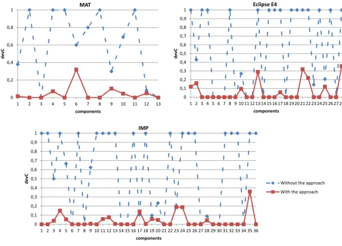
Figure 7 shows the results of the objective function DevC for each component from each application. In each graph, at the same time are represented the results related to the interfaces derived with our approach (solid line) and those declared in the manifest file of components (dashed line). We can notice that the results are much better for components with interfaces that were proposed by our approach. In some cases they are not the same set of services which are considered in the calculation of a component DevC. This is the case when some methods of a class are used while the latter does not belong to an exported package.
It is true that the penalty assigned to unused interfaces (1 for DevI) degrades the result of the declared component interfaces. But, at the same time it also shows how the components were poorly designed in terms of defining their
MAT Eclipse E4 IMP 0 0,2 0,4 0,6 0,8 1 1 2 3 4 5 6 7 8 9 10 11 12 13 d e v C components 0 0,1 0,2 0,3 0,4 0,5 0,6 0,7 0,8 0,9 1 1 2 3 4 5 6 7 8 9 10 11 12 13 14 15 16 17 18 19 20 21 22 23 24 25 26 27 28 d e v C components 0 0,1 0,2 0,3 0,4 0,5 0,6 0,7 0,8 0,9 1 1 2 3 4 5 6 7 8 9 10 11 12 13 14 15 16 17 18 19 20 21 22 23 24 25 26 27 28 29 30 31 32 33 34 35 36 d e v C components
Without the approach With the approach
Fig. 7. Comparative results for DevC before and after the use of our approach
interfaces.
C. Discussion
The obtained results are the same regardless of the appli-cation, as shown in Figure 7. Thus, the problem is not related to the context of the application (scope or development team). The common element is the use of object-oriented approach for building components.
The other problem we have noticed is the use of an already existing packages for declaring interfaces. Indeed, with the OSGi framework provided interfaces are declared in a package to export. But programmers use classes that already belong to packages, while the latter are designed for object-oriented design. The logic used to group classes in a single package, according to the object-oriented approach does not correspond to the logical grouping of features according to aspects. This is highlighted by i) the number of interfaces declared by components (in their exported packages) which are not used by the other components. ii) the existence of interfaces that are used but do not belong to exported packages (see Table IV).
The results obtained with our approach depends on the maximum number of interfaces per component set by the designer. Not knowing the semantics of each component of each application, we set this number at 1.5 times greater than
the number of user components of each component. There is no doubt that a good knowledge of the components makes it possible to set the limit of the number of interfaces to the correct value and thus get better results.
V. THREATS TO VALIDITY
Our study may be concerned by internal and external threats to validity. We discuss below these two kind of possible threats.
A. Internal Validity
The internal validity is threatened by the chosen tool to extract dependencies between components. We used the JDT Eclipse parser to build the static call graph. Indeed, if dependencies are extracted from a dynamic call graph (actual calls), they may be a little bit different from those obtained from a static call graph. The dynamic call graph may contain calls related to classes dynamically loaded and may miss calls that the used use cases do not cover.
The number calls related to classes dynamically loaded is very small wrt to calls within an application. Thus, they do not impact the results of our study. But, the number of possibly missed calls by use cases may be important. Indeed, it is hard to get use cases covering all possibilities of an application.
That is why we chose the use of a static call graph to extract dependencies between components.
B. External Validity
The external validity is threatened by the language and the framework with which the chosen applications have been developed. We chose applications developed with the Java language. As our study is based on static calls, we do not believe that the results may be different with another object-oriented language. We have chosen the OSGi framework because there are no additional classes that the business classes have to interact with.
The use of our approach for redefining interfaces of already existing components, constructed within a framework that adds its own classes (eg. J2EE), can give an inconsistent result. But our approach has been built to be integrated in a process of restructuring of object-oriented applications into component-based applications. In this case, there are only application-specific classes.
VI. CONCLUSION
According to Lehman’s first law [14], software systems must be continually adapted, or they become progressively less satisfactory. In the same time, the software evolution is becoming more and more complex and expensive. This is explained by the Lehman’s second law [14] which states that
as a software system evolves its complexity increases unless work is done to maintain or reduce it. Given the advantages of the component paradigm, re-engineering object-oriented applications into component-oriented applications seems to be a promising choice. It helps companies reducing their software maintenance and evolution costs. Especially if this process is automated in a large part. In this context, automated identifi-cation of components and their interfaces is an important first step. In this paper, we have proposed an interface identification approach that is defined as a continuation of a component identification process. The aim is to build a consistent and understandable architecture that facilitates the maintenance and/or the mapping of the application to a concrete a com-ponent model.
Our study of existing applications has shown how the designer is influenced by the object paradigm when designing her/his components. In case of a correctly built application, but mainly with component on the shelf, our objective function can give unsatisfactory results. Indeed, the latter are often generic in order to cover a wide space of application domains. So they can hold aspects that are not relevant to the target application. However, our objective function can be used to choose between competing components to minimize the size of unnecessary code in the application.
To project an architecture, which is extracted with our approach, on an existing component framework, we can use the fac¸ade and the factory design patterns. For the latter, its use can raise some difficulties. Indeed, the life-cycle of objects from a group of classes (component) is somehow managed by some third parties in the legacy application. To put their life-cycle within the component that holds the concerned classes, we need first to conduct a study on the dynamics of these objects in order to reproduce it within the component. This aspect will constitute our main future work.
REFERENCES
[1] S. Allier, S. Sadou, H. Sahraoui, and R. Fleurquin. From object-oriented applications to component-oriented applications via component-oriented architecture. In 9th IEEE/IFIP Working International Conference on Software Architecture (WICSA), pages 214–223, Washington, DC, USA, june 2011. IEEE Computer Society.
[2] S. Allier, H. A. Sahraoui, and S. Sadou. Identifying components in object-oriented programs using dynamic analysis and clustering. In
Proceedings of the 2009 Conference of the Center for Advanced Studies on Collaborative Research, CASCON ’09, pages 136–148, New York, NY, USA, 2009. ACM.
[3] S. Allier, H. A. Sahraoui, S. Sadou, and S. Vaucher. Restructuring object-oriented applications into component-oriented applications by using consistency with execution traces. In CBSE, pages 216–231, 2010.
[4] N. Anquetil and T. C. Lethbridge. Recovering software architecture from the names of source files. Journal of Software Maintenance, 11(3):201–221, 1999.
[5] S. C. Choi and W. Scacchi. Extracting and restructuring the design of large systems. IEEE Software, 7(1):66–71, 1990.
[6] L. Chouambe, B. Klatt, and K. Krogmann. Reverse engineering software-models of component-based systems. In12th European Con-ference on Software Maintenance and Reengineering (CSMR), pages 93–102, april 2008.
[7] U. Dekel and Y. Gil. Revealing class structure with concept lattices. In
Proceedings of the 10th Working Conference on Reverse Engineering, WCRE ’03, pages 353–, Washington, DC, USA, 2003. IEEE Computer Society.
[8] S. Ducasse and D. Pollet. Software architecture reconstruction: A process-oriented taxonomy. IEEE Transactions on Software Engineer-ing, 35:573–591, 2009.
[9] B. Ganter and R. Wille. Formal concept analysis - mathematical foundations. Springer, 1999.
[10] D. Garlan. Software architecture: a roadmap. InProceedings of the Conference on The Future of Software Engineering, ICSE ’00, pages 91–101, New York, NY, USA, 2000. ACM.
[11] R. S. Hall, K. Pauls, S. McCulloch, and D. Savage. OSGi in action : creating modular applications in Java. Pearson Education, Greenwich, Conn. Manning London, 2011.
[12] S. D. Kim and S. H. Chang. A systematic method to identify software components. InAPSEC, pages 538–545, Washington, DC, USA, 2004. IEEE Computer Society.
[13] J. K. Lee, S. J. Seung, S. D. , W. Hyun, and D. H. Han. Component identification method with coupling and cohesion. InAPSEC, pages 79–86, Washington, DC, USA, 2001. IEEE Computer Society. [14] M. M. Lehman. On understanding laws, evolution, and conservation
in the large-program life cycle. Journal of Systems and Software, 1(1):213221, 1980.
[15] C. Lindig and G. Snelting. Assessing modular structure of legacy code based on mathematical concept analysis. InICSE, pages 349–359, 1997. [16] J. Lundberg and W. L¨owe. Architecture recovery by semi-automatic component identification. Electr. Notes Theor. Comput. Sci., 82(5):98– 114, 2003.
[17] S. Mancoridis, B. S. Mitchell, and C. Rorres. Using automatic clustering to produce high-level system organizations of source code. InIn Proc. 6th Intl. Workshop on Program Comprehension, pages 45–53, 1998. [18] F. Martin, M. Kessentini, and H. Sahraoui. Deriving high-level
abstrac-tions from legacy software using example-driven clustering. In Inter-national Conference on Computer Science and Software Engineering, CASCON ’11, pages 188–199, 2011.
[19] N. Medvidovic and V. Jakobac. Using software evolution to focus architectural recovery.Automated Software Eng., 13(2):225–256, 2006. [20] H. A. Muller, M. A. Orgun, S. R. Tilley, and J. S. Uhl. A reverse-engineering approach to subsystem structure identification. Reverse Engineering, 5(4):181–204, 1993.
[21] A. Pourhaji Kazem and S. Lotfi. An evolutionary approach for partitioning weighted module dependency graphs. In Innovations in Information Technology, 2007. IIT ’07. 4th International Conference on, pages 252 –256, nov. 2007.
[22] T. Richner and S. Ducasse. Recovering high-level views of object-oriented applications from static and dynamic information. In Pro-ceedings ICSM99 (International Conference on Software Maintenance, pages 13–22. IEEE, 1999.
[23] C. Riva and J. V. Rodriguez. Combining static and dynamic views for architecture reconstruction. InSixth European Conference onSoftware Maintenance and Reengineering (CSMR), pages 47–55. Nokia Research Center, 2002.
[24] M. Saeed, O. Maqbool, H. A. Babri, S. Z. Hassan, and S. M. Sarwar. Software clustering techniques and the use of combined algorithm. In Proceedings of the Seventh European Conference on Software Maintenance and Reengineering, CSMR ’03, pages 301–, Washington, DC, USA, 2003. IEEE Computer Society.
[25] H. A. Sahraoui, W. Melo, H. Lounis, and F. Dumont. Applying concept formation methods to object identification in procedural code. In
Proceedings of the 12th international conference on Automated software engineering (formerly: KBSE), ASE ’97, pages 210–, Washington, DC, USA, 1997. IEEE Computer Society.
[26] R. W. Schwanke and S. J. Hanson. Using neural networks to modularize software. Machine Learning, 15(2):137–168, 1994.
[27] G. Snelting and F. Tip. Reengineering class hierarchies using concept analysis. In Proceedings of the 6th ACM SIGSOFT international symposium on Foundations of software engineering, SIGSOFT ’98/FSE-6, pages 99–110, New York, NY, USA, 1998. ACM.
[28] P. Tonella and M. Ceccato. Migrating interface implementation to aspects. Software Maintenance, IEEE International Conference on, 0:220–229, 2004.
[29] A. van Deursen and T. Kuipers. Identifying objects using cluster and concept analysis. InICSE, pages 246–255, 1999.
[30] A. van Deursen and T. Kuipers. Identifying objects using cluster and concept analysis. InProceedings of the 21st international conference on Software engineering, ICSE ’99, pages 246–255, New York, NY, USA, 1999. ACM.
[31] A. van Deursen, M. Marin, and L. Moonen. Aspect mining and refac-toring. InProceedings First International Workshop on REFactoring: Achievements, Challenges, Effects (REFACE). University of Waterloo, Canada, nov 2003.
[32] H. Washizaki and Y. Fukazawa. A technique for automatic component extraction from object-oriented programs by refactoring. Sci. Comput. Program., 56(1-2):99–116, 2005.
[33] H. Yan, D. Garlan, B. Schmerl, J. Aldrich, and R. Kazman. Discotect: A system for discovering architectures from running systems. Interna-tional Conference on Software Engineering, pages 470–479, 2004.