Mobile Decoder Manual
Includes:
Decoder Selection & Installation Basics
Programming & Configuration Variables
Real FX & FX
3Set Up & Use
Scaleable Speed Stabilization (Back EMF) Set Up
SuperSonic Operation (Silent Operation)
Loadable Speed Tables
Transponding
™Troubleshooting
Digitrax, Inc.
2443 Transmitter Road
Panama City, Florida 32404
(850) 872 9890 - Fax (850) 872 9557
www.digitrax.com
LLooccooNNeett R
Digitrax Manuals & Instructions are updated periodically. Please visit www.digitrax.com for the latest version of all manuals.
This manual was updated 8/10
C
T
C
omplete
rain
ontrol
1.0 Introduction 5 2.0 Digitrax Decoder Features & Specifications 5
3.0 Decoder Installation 7
3.1 9 Steps For Successful Decoder Installation 8 3.1.1 Avoiding Heat Problems With Decoder Installations 8 3.2 Recommended Tools for Decoder Installation 8
3.3 Choosing a Locomotive 9
3.4 Choosing The "Right" Decoder 9 3.4.1 Is There a Plug ‘N Play Decoder? 9 3.4.2 What Is Your Loco's Stall Current? 10 3.4.3 Which Decoder Will Fit? 11 3.4.4 Other Decoder Functions and Features? 11 3.5 LT1 LocoNet Cable & Decoder Tester 13
3.6 Locomotive Disassembly 15
3.7 Isolate the Motor 15
3.8 Decoder Interfaces 16
3.8.1 Plug ‘N Play Interfaces 16
3.8.2 Digitrax 9 Pin HO Decoder Interface 17 3.8.3 Installing Decoders with Wires 18 3.9 Installing Lighting Effects 21
3.10 Final Decoder Test 22
4.0 Troubleshooting 23
4.1 The decoder won't respond 23 4.2 The decoder runs for a while & then just stops 24 4.3 Loco operation is jerky & erratic 24 4.4 "Strange" locomotive light operation 24 4.5 The locomotive won't move at all 25 4.6 Locomotive "buzzes" 25
4.7 The Quarter Trick 25
4.8 The LT1 tester 25 4.9 Getting Help 26
Digitrax Mobile
Decoder Manual
Table of Contents R R5.0 Decoder Programming 26
5.1 What are CVs? 26
5.2 Programming Modes: Paged, Physical Register, Direct & Ops 26 5.3 DCC Outputs For Programming & Train Operation 27 5.4 Reading & Writing CVs 27
6.0 Configuration Variables 28
6.1 Decoder Addresses 31
6.1.1 Decoder 2 Digit Address: CV01 31 6.1.2 Decoder 4 Digit Address: CV17 & CV18 32 6.2 Configuration Register: CV29 32 6.2.1 Characteristics Controlled by CV29 32 6.2.2 Determining CV Value To Program Into CV29 33
6.3 V-start: CV02 36 6.4 Acceleration Rate: CV03 36 6.5 Deceleration Rate: CV04 37 6.6 V-max: CV05 37 6.7 V-mid: CV06 37 6.8 Factory Reset CV: 08 38
6.9 Analog Functions Enable/Disable: CV13 38 6.10 Digitrax Special Light Effects: CV49-CV63 & CV113-CV116
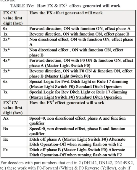
39 6.10.1 Setting Up FX & FX3Effects On Function Outputs 40
6.10.2 Customizing FX & FX3Effects CV62 44
6.10.3 Ditch Light Hold Over Time CV63 44
6.10.4 FX Examples 45
6.10.5 Troubleshooting FX effects 46 6.10.6 Setting Up A Master Light Switch with FX3Decoders 46
6.10.7 Setting Up Configurable Strobes CV49, CV50, & CV61 46 6.10.8 Lamp Selection For Prototypical Lighting Results 47 6.10.9 Setting Up Non-FX Functions with FX3 48
6.11 CV53 & CV54 Torque Compensation & Switching Speed 49
6.12 Function Remapping 50
6.13 Throttle Response Curves & Loadable Speed Tables 52 6.13.1 Simple 3 Step Speed Tables with V-max, V-mid & V-start 53 6.13.2 High Resolution 28 Step Speed Tables CV65-95 53 6.14 CV61 Non-directional Headlights, Transponding™ & Split Phase
Motor Drive 57
6.14.1 Non-Directional Headlight Operation 57 6.14.2 Split Field/AC Motor Drive 58 6.14.3 Transponding Enabled/Disabled 58 6.15 Scaleable Speed Stabilization (Back EMF): CV55, 56 & 57 58
6.17 Advanced Consisting Controls CV19, CV21 & CV22 62
7.0 Operation With Digitrax Compatible Command Stations 63 8.0 Analog Operation of Digitrax Decoders 63
Appendix A: Decimal & Hex Numbers 64
Warranty & Repair Information 67
Digitrax, LocoNet, Genesis, Genesis II, Empire Builder, Super Empire Builder, Super Empire Builder Xtra, Empire Builder II, Chief, Chief II, Super Chief, Super Chief Xtra, Radio Equipped, Challenger, Big Boy, AutoReversing, FX, UniVersal Consisting, Zephyr, Transponding, Jump, SoundFX and others are trademarks of Digitrax, Inc.
Digitrax, Inc. is not responsible for unintentional errors or omissions in this document.
1.0 Introduction
Congratulations on your purchase of a Digitrax Digital Command Control Decoder. It is engineered to give you exciting DCC control features at a rea-sonable price. Digitrax mobile decoders work with DCC compatible systems. Many Digitrax decoders also go beyond DCC compatibility to offer additional non-DCC features like real FX effects, analog mode conversion, speed stabi-lization, Transponding™ and more.
Digitrax offers many decoders that are plug ‘n play, making installation a snap. In some cases decoder installations are more challenging and may require sol-dering. Most model railroaders have the common sense, judgment and skills needed to successfully install decoders. It is important to follow the directions included in this manual and on the decoder specific instructions you receive with each decoder to make sure your installation is successful. If you choose to have someone else install decoders in your locomotives, your local Digitrax authorized dealer can handle the installation or can refer you to someone who can do the job for you.
A word of caution: DCC offers many options that are not available with DC operation. We recommend that you begin by running trains at different speeds in forward and reverse as you did with DC control. Once you are comfortable with basic locomotive operation, then move on the more advanced options available with DCC. Before you know it, you will be running your model trains like the prototype!
Thank you for choosing Digitrax! Please feel free to contact Digitrax or your Digitrax Authorized Dealer with any questions or concerns you might have about our products. We are always looking for ways to make our products bet-ter so, let us know what you think!
2.0 Digitrax Decoder Features & Specifications
Digitrax mobile DCC decoders are just one part of your DCC system. When properly installed in your locomotives, they will receive the commands sent from your command station through the rails, decode the commands and con-trol the motor and function operation of your locomotives.
Digitrax makes a wide variety of decoders with many different features. This lets you choose which decoder is best for each individual locomotive. All Digitrax decoders are robust, reliable and quiet running.
Digitrax builds economy decoders with fewer features, mid range decoders with more features and premium decoders with even more advanced features.
The Decoder Instruction Card included with your decoder lists the features of the decoder and includes specific information about how to install the decoder. This Manual explains most of the features available in Digitrax decoders. The latest versions of this Manual and the Decoder Instruction Cards is available at www.digitrax.com.
Spec sheets and instruction sheets for all Digitrax decoders past and present are available at www.digitrax.com
Digitrax Decoder Part Numbering System
Current production Digitrax decoders use the following numbering system:
The first character tells you it is a digital decoder. This is always a “D”.
The second character tells you what size it is. This is based on the smallest "scale" the decoder is designed to fit. This will be a Z, N, H, or G.
The third character tells you the current rating of the decoder. This will be a 1, 2, 3, 4 or 5. We designate 1.25 & 1.5 amp decoders as 1s and 3.5 amp decoders as 3s for simplicity.
The fourth character tells you how many functions, including directional lights, are available on the decoder.
The fifth character is a Digitrax series designator. This is a number from 0-9. Series 1 Digitrax decoders have standard or configurable strobe function out-puts. Series 2 decoders have FX function outputs, Scaleable Speed Stabilization (Back EMF) and Transponding™. Series 3 decoders with 6 functions have FX3
function outputs, torque compensation, SuperSonic™ (silent operation), Scaleable Speed Stabilization (Back EMF) and Transponding™. Series 3 decoders with less than 6 functions have a modified set of features. See decoder descriptions for actual features embodied in each decoder.
Additional letters may be added to the decoder number to indicate which installation interface is used on the decoder. If the decoder number ends after the series number, then it is a wired decoder.
Numbering Examples:
DH163is a mobile decoder that fits in HO scale, is rated for at least 1 Amp & has 6 functions available. This decoder is actually rated at 1.5 Amps. This is a series 2 decoder.
DN121is a mobile decoder that fits in N scale, is rated at 1 Amp & has 2 func-tions available with standard or configurable strobe funcfunc-tions. This is a Series 1 basic decoder.
DH163IPis a mobile decoder that fits HO scale, is rated for at least 1 Amp, has 6 functions available and uses the integrated DCC medium plug interface to plug into locos. This is a FX3decoder with FX3, torque compensation,
SuperSonic™ silent operation.
3.0 Decoder Installation
Decoder installation is not as difficult as you might think. Follow these simple steps carefully and you will be comfortable with the procedure in no time. Each Digitrax decoder comes with an instruction sheet that shows you the specifics of how to install it in a locomotive.
3.1 9 Steps For Successful Decoder Installation
3.1.1 Avoiding Heat Problems With Decoder Installations
Most HO, N & Z Scale model locomotive motors and lamps are
designed by the locomotive manufacturers to operate at full speed at 12 volts DC on the track. Digitrax recommends running your DCC command station and boosters at the lowest track voltage possible that provides acceptable operation.The “N Scale (12V)” setting on Digitrax equipment works for most HO, N & Z scale layouts. Some DCC systems made by other companies supply more voltage to the track and are not adjustable. If the track voltage applied exceeds the operating parameters of the locomotive and its lamps, it is possible for overheating to damage your locomotive whether you use DC or DCC. For example, running an N Scale locomotive that was designed to run on 12-14 volts on a system that supplies 12 or more volts to the track may cause overheating and damage to the locomo-tive, its shell and your decoder.
3.2 Recommended Tools for Decoder Installation
You'll need a few simple tools when you begin installing decoders: 1. A soldering iron, preferably temperature controlled. Though many
installations do not require soldering, you may still need to use a sol-dering iron to install extras like lamps for special lighting effects. 2. Solder.
3. A small screwdriver for disassembling your loco. 4. Small diagonal cutters for cutting & stripping small wire. 5. Tweezers to pick up small loco parts.
6. Heat shrink tubing for protecting wire connections, this is better than electrical tape.
1. Read the instructions FIRST and PLAN your installation. Have the proper tools on hand.
2. Choose a locomotive that runs well on regular DC. 3. Choose the appropriate decoder for your installation. 4. Test the decoder before installation.
5. Carefully disassemble the loco. 6. Isolate the motor!
7. Follow the decoder's wiring diagram or installation instruc-tions.
8. Test the installation first on DC then on DCC. (If the lights are flashing the first time you apply power, remove the loco from the track and locate the short circuit in your installa-tion.)
7. Tape for securing wires and the decoder inside the locomotive. 8. Decoder installation should be done in a reasonably static free
envi-ronment. We recommend that you do all installations on a non-metallic surface. Digitrax decoders are not overly sensitive to static electricity & with a little common sense, you won't have problems.
3.3 Choosing a Locomotive
Choose a locomotive that runs well on conventional DC power. Digital decoders cannot compensate for faulty motor operation, poor track pickup, etc. If you are not happy with the way your locomotive runs on regular DC power, installing a decoder will not make it run any better.
If there are any mechanical issues with your locomotive, fix them before you install the decoder. Since you have to open up the loco anyway, do a tune up to get it running really well before you put in the decoder. Digitrax recommends using a conductive brush lubricant like Aero Car Technology's "Conducta" brush lubricant to minimize brush noise in all locos. Be sure the brushes are making good con-tact and that the commutator is reasonably clean.
Decide where the decoder will fit inside the loco. Is there space to put the decoder or will you need to "make room?" Is there a plug ‘n play decoder for the loco? Digitrax offers a variety of decoder sizes, form factors and current ratings to accommodate almost any loco-motive. Decoders from other companies that make compatible DCC decoders may fit better in some of your locos, too. If there is just nowhere in the locomotive to install a decoder, you can run it on your Digitrax system as an analog locomotive on address "00."
3.4 Choosing The "Right" Decoder
4 Steps To Choosing the Right Decoder for Your Loco
1. Is there a plug ‘n play decoder or other decoder made for your specific loco? Check www.digitrax.com for specific decoder recommenda-tions for specific locomotives. If so, you can skip steps 2 & 3. 2. What is the stall current of the motor in the locomotive?
3. How much room do you have available inside the loco for installa-tion?
4. Do you want a decoder that does more than motor control and head-lights? Do you want special lighting effects (FX)? Do you want decoders with Scaleable Speed Stabilization (Back EMF) or Transponding™?
3.4.1 Is There a Plug ‘N Play Decoder?
Digitrax maintains a list of decoder recommendations for specific locomotives on the web site www.digitrax.com. Most Digitrax authorized dealers can also
help you determine which decoder will work best in your locomotive. If you can't find a recommended decoder for your locomotive, then proceed to the steps outlined in 3.4.2 & 3.4.3.
3.4.2 What Is Your Loco's Stall Current?
For HO applications, most modern high efficiency can motors draw less than 1/2 Amp when running and less than 1 Amp when stalled at 12V DC. These motors are suitable for use with 1 Amp & 1.5 Amp decoders. Some older HO motor designs (older Athearn open frame motors, Pittman motors, etc.) may exceed these limits and you may need to use a higher current decoder in these applications for better long term reliability.
For N scale applicationsmost modern high efficiency can motors draw less than 1/2 amp when running and less than 1 amp when stalled at 12V DC. However, we have found that many high performance N-scale locos actually draw more than this when properly tested. To ensure long-term reliability, Digitrax recommends that all N-scale decoders have a current rating of at least 1 amp. All current production Digitrax decoders are rated at 1 amp or more.
For large scale equipment, it is particularly important to test the specific loco you will use to determine the appropriate decoder to use. In many cases O, S, O-27 & G scale Digitrax 2 amp decoders will be just right. However, in other cases, especially where 2 motors are involved, Digitrax 3-5 amp decoders will be a better choice.
How to Determine The Stall Current Of A Locomotive
1. Place the loco (without the shell) on a track powered with regular DC at 12V for HO & N Scales (Use 16V for G Scale).
2. Attach a DC current meter (ammeter) in series with one of the track feeds. If you have one of the commercially available power packs that have an ammeter, it will work for this pur-pose.
3. Apply DC power to the track.
4. Stop the motor from rotating by holding the fly wheel or drive shafts for a couple of seconds and measure the current that the unit is drawing from the power pack while the motor is stalled. 5. Be sure that the power pack voltage remains at 12V (16V for G
Scale) during this test to be sure you get an accurate stall cur-rent measurement.
6. Choose a decoder with at least the current rating determined with this test. Digitrax recommends using the decoder with the high-est current rating that will fit in your locomotive to improve long term reliability.
3.4.3 Which Decoder Will Fit?
The space available inside the locomotive is a major factor in choosing which decoder to use for your installation. Many sizes & form factors are available.
For N scale, there are replacement frames available to simplify your installa-tion in locos that don't have plug ‘n play soluinstalla-tions. For milled N scale frames contact Aztec Manufacturing directly. For cast N scale frames, contact your local dealer for Southern Digital Frames.
For HO scale, there is the option of using N or Z scale decoders in tiny spaces as long as the current rating of the decoder is at least 1 amp.
The Digitrax web site, www.digitrax.com, has links to application notes for many different locomotives. Digitrax users have come up with some really cre-ative decoder installations!
3.4.4 Other Decoder Functions and Features?
Once you have determined the current rating and decoder size needed for your loco, consider other things you want your decoder to do.
Functionsare things like: lamps, sound units, smoke units, etc. All Digitrax decoders are equipped with two or more function outputs that are used to turn functions on and off.
Function outputs can be in the form of :
1. Leads (wires) attached to the decoder that are used to hook up exter-nal functions.
2. Pre-wired function outputs that hook up by just plugging in the decoder.
3. Solder pads on the decoder that allow you to solder wires to hook up functions to the decoder.
Some decoders have more than one form of function output. For exam-ple, the DN163K0a has two function outputs pre-wired to the white LEDs on the decoder and 4 additional solder pads available for adding wires to hook up more functions.
If you are planning to operate more functions in addition to headlight control you will need to use a decoder with more function outputs. For applications where you are using a sound module, you will want a decoder with at least 4 or 5 functions. Function only decoders, like the TL1, TF2 & TF4, are also avail-able if you wish to add even more functions.
There are five types of functions available on Digitrax decoders: Standardfunctions turn functions on and off. Digitrax decoders with
automatically reversing or individually controllable.
Standard* functions turn functions on and off. These decoders offer automatically reversing head lights only.
Configurable strobe (CS)functions can be set up to run as simple on/off or as single or double pulse strobes.
FX functionsincorporate generators for prototypical lighting effects, like Mars lights, ditch lights, Gyralites, random flicker, single & double pulse strobes, etc.
FX3functionsincorporate FX generators with additional dynamic and
static qualifiers. FX3functions are fully remappable so they can be
controlled by any function key on your system. A master light switch can be set up to turn off all lights on a locomotive. Functions associated with advanced consists can be controlled, too.
Function outputs on Digitrax decoders are available in several current rat-ings depending on the decoder:
Scaleable Speed Stabilization (Back EMF): Some Digitrax decoders are equipped with this feature that lets you set up "cruise control" for your locomo-tives. This can be used to smooth out operation in the low end speed range, to run locos at the same speed no matter the track grade or to improve operation of steam loco mechanisms.
Torque Compensation for smooth as silk operation. This feature improves loco performance by adjusting for the loss of torque due to high frequency PWM associated with SuperSonic™ silent operation.
SuperSonic™ motor drive for silent operation. Digitrax SuperSonic™ is Transponding™ compatible and does not have to be switched off when transponding is in use on the layout.
a specific transponder equipped loco on a layout that is equipped with transponder detectors. This feature is integrated in some Digitrax decoders. If your decoder does not have an integrated transponder, you can add a stand alone transponder to the locomotive later if desired. Transponders can also be added to rolling stock that does not have a DCC decoder. Digitrax transponding does not require any additional modifications or inductors to be added to your locos, rolling stock or system boosters
Multi-Format: This decoder feature let's you run your loco on other digital format layouts. The decoder automatically detects whether it is receiving DCC, Motorola Trinary or Analog commands and responds to the appropriate com-mands. This feature is very popular in Europe where many different digital command control formats are used.
3.5 LT1 LocoNet Cable & Decoder Tester
Once you have chosen the decoder you will use for your installation, Digitrax recommends that you test it before installation. The test procedure will famil-iarize you with how the decoder works and how to hook up the wires. Testing gives you verification that the decoder is working before you install it. Decoders leave the factory fully tested and ready to go, but it is always com-forting to be sure they work as advertised before installing a decoder in your locomotive. This is especially true for anxious first time installers!
Use the LT1 that came with your Digitrax Starter Set to perform the test. There are other commercially available decoder testers made by third party manufac-turers.
Digitrax will gladly repair or exchange any decoder that you are not convinced works correctly after performing the test procedure outlined. If there is a prob-lem, please call or e-mail for technical assistance before returning the decoder for repair. Many times problems can be solved by phone. Do not install any decoder that does not pass this test.
LT1 LocoNet Cable Testing Instructions
1) Disconnect the harness from the LT1.
2) Plug one end of the cable being tested into the LT1.
3) Connect the other end to any Digitrax Booster LocoNet Connection Jack A or B. Be sure you have at least one Digitrax throttle con-nected to LocoNet.
4) All four LEDs on the LT1 will light if the cable is good. LEDs may not all have the same brightness, this is normal.
5) If any of the LEDs fail to light, remove the plug from the end of the cable and crimp on another plug and re-test.
LT1 Decoder Testing Instructions
1. Strip the insulation from the red, green, black, and yellow wires. The blue and white wires are not used and may be cut off the harness. 2. Twist the red and yellow wires together. Twist the black and green
wires together. (see above) 3. Hook up decoder as shown here.
4. Use your throttle to select the decoder and run it in the forward direc-tion.
5. One of the two center LEDs will light as the motor voltage increases from the decoder. Change direction and the other LED will light. 6. Test the other decoder function outputs by connecting the LT1 to the
blue decoder common and one of the function outputs.
7. Use your throttle to turn the function on and off . One of the two cen-ter LEDs will go on and off with the function. Do this test for all function outputs separately.
3.6 Locomotive Disassembly
Each Digitrax decoder comes with an instruction card. Before you begin your installation, be sure to read the specific instructions that came in your decoder package in addition to reading this manual.
1. Disassemble your loco carefully.
2. Note how + and - motor connections & the left & right power pick up connections are set up.
3. Look carefully at the loco’s wiring & determine where all the wires go and what they do before changing or disconnecting any of them. The physical location of the decoder in the loco is important and may involve sculpting plastic and or metal parts to allow enough room for installation. Install the decoder in the coolest part of the loco body. Recommended operat-ing temperatures should be between 70 & 120 degrees Fahrenheit (20-50 degrees Celsius). The decoders will provide more power to your motors if they are installed away from heat sources inside the locomotive body, e.g., motors and lamps.
When making wire connections inside the loco, use the shortest length of wire that will do the job. After the wires are attached and insulated with heat shrink sleeving, secure them so that repeated removal and replacement of the locomo-tive shell won't pull the wires loose.
The biggest cause of decoder failure after initial installation is wires being pulled loose and shorted to the frame when the shell is removed or replaced.
3.7 Isolate the Motor
For DC permanent magnet powered locomotives, the decoder must be electri-cally inserted between the track power pickups and the 2 motor brushes.
The most important part of any successful locomotive conversion is proper electrical isolation of the 2 motor brush connections, so that they are driv-en only by the decoder. Failure to isolate the motor will damage your decoder. Damage caused by failure to isolate the motor is specifically exclud-ed from the warranty.
Once you have the motor isolated, visually inspect the brushes again, just to be sure. Use a reliable continuity checker (beeper box) to be sure there is an OPEN circuit (very high resistance) from both brushes to any other part of the locomotive chassis or power pickups and wheels. Check both motor brushes. If
the circuit is not open, your beeper box will beep.
Only when you are satisfied that the motor is isolated, should
you proceed with the decoder installation.
Some motor brush power connections may be tricky, like a spring to or inter-ference fit with part of the chassis. Some locos pick up brush power from the chassis through a spring. In this case, after removing the spring connection to the brush, wire the corresponding decoder power input to the chassis. Examine the loco carefully to determine how power moves from the track pickups to the motor.
Decoders with FX3functions have motor isolation protection. If the decoder
senses that the motor is not isolated, it will not run the motor. In this case, you will be able to control the loco’s functions but the motor will not work.
Decoders with FX functions will blink the loco's lights when power is first applied to the decoder to warn you of a short circuit in your installation. If you see the lights blinking, immediately remove the loco from the track, locate the short circuit and correct the problem before proceeding. Do not leave the loco on the track with blinking lights because eventually, the decoder will become overloaded and be damaged. If a short occurs after initial installation, the lights will not blink so, it is important to secure the leads inside the loco once the installation is complete to prevent them from coming loose during normal operation and creating a short. For board decoders, it is important to follow the instructions for installing insulating tape inside the loco to prevent shorts during operation caused by the decoder board shifting inside the engine.
3.8 Decoder Interfaces 3.8.1 Plug ‘N Play Interfaces
Many locomotives come from the factory with provisions for easy decoder installation. You can even buy some locomotives that are decoder equipped! Manufacturers use several terms for these locos.
DCC Ready Locomotives: These locomotives are usually equipped with a DCC medium socket, though you may find some locos where this terminology means that there is room for a decoder. Be sure to check this before purchas-ing the loco.
DCC Medium Socket: This diagram shows the DCC medium plug that is widely used with HO locomotives that come from the manufacturer with the DCC medium socket. The color code refers to the wire colors on a DCC wire harness. To install a decoder in a loco with a DCC medium socket, remove the dummy plug that comes with the locomotive and insert a decoder with a DCC medium plug in the socket.
Digitrax 9 Pin:The Digitrax 9 pin socket & plug is another commonly used DCC plug ‘n play interface that is available in some HO locos.
Plug ‘N Play Locomotives and Decoders: In this case specific decoders are designed for specific locomotives. Plug ‘N Play installations require you to remove an existing circuit board and replace it with a plug ‘n play decoder.
Solderless Decoder Installations: Solderless installations are the answer in some cases where the loco does not come with a circuit board, like Athearn standard locos. In these locos, a special harness is used with your decoder. To do this kind of installation, simply remove and reinstall clips at several loca-tions inside the locomotive.
Decoder Equipped Locomotives: These locomotives are equipped with decoders at the factory. These pre-installed decoders generally have minimal features. If you want additional features, you may wish to replace the decoder that came with a loco with one that has more features. In some cases you have the option to purchase a loco with or without a decoder. You should evaluate the features offered before deciding which one best fits your needs. All DCC compatible decoders shipped with locomotives should work with your Digitrax system.
3.8.2 Digitrax 9 Pin HO Decoder Interface
Most Digitrax HO scale wired decoders come with a plug and socket on the decoder so that the wires can be unplugged from the decoder. This interface lets you share one or more decoders among multiple locomotives wired with Digitrax 9 pin harnesses. DHWH is the wire harness with a plug that attaches
11
22
33
44
55
66
77
88
B l a c k B l a c k N o C o l o rN o C o l o r Y e l l o wY e l l o w O r a n g eO r a n g e R e d R e d B l u e B l u e W h i t e W h i t e G r a y G r a yto your DH series decoders and 9 wires that are soldered to the motor, brushes and functions on your locomotive. DHDP is a DC dummy plug available for DC operation of harnessed locomotives (without decoders). When you install a DHWH wire harness in your locomotive and plug a DHDP dummy plug into it, your loco will operate on any analog control system. When you remove the DHDP and plug in a decoder, the loco will run on DCC. The Digitrax 9 pin interface gives you a cost effective way for clubs and large layouts to share the decoders they have and run with Digitrax even if all locos can't be converted right away.
The DHWHP wire harness has a Digitrax 9 pin plug on one end and DCC medium plug on the other end. DHWHPS is the same with shorter wires. DHAT is a wire harness with Digitrax 9 pin on one end and clips for solderless installation in a standard Athearn diesel locomotive.
To separate a Digitrax decoder from the Wire Harness:
Firmly pinch all 9 wires between thumb and forefinger about 5/8" back from the plug. Grasp the decoder body on the sides right next to the socket to ensure no stresses are placed on components under the protective sleeve. Pull gently and evenly on all 9 wires simultaneously. It is important to distribute the force needed to separate the plug and socket EVENLY over all the wires to prevent damaging the plug by pulling a single wire out of the plug. It is easier to remove the plug if you gently rock it from side-to-side. After the first few times you connect and disconnect the plug, it will be easier to do. Be sure to keep the plug and socket free of dirt and debris.
3.8.3 Installing Decoders with Wires
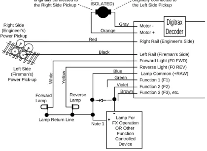
In some cases, especially in older locomotives, brass locomotives and really tiny locomotives, there is no easy way to install decoder available. In these cases, you must install a decoder with wires. Refer to TABLE Iand Figure 1 and the specific instruction card that came with your decoder along with these instructions. Each decoder is equipped with the wires necessary to provide the functions available for that particular decoder. All decoders do not have all the wires described here. See Figure 2for lamp installation information.
Figure 1: Digitrax Decoder Wiring Diagram
Figure 1 Notes:
Do not exceed the decoder's total function output current rating. If lamp com-mon is not used, connect function power to either track power pick up. The directional light function "Lamp Return Line" can be hooked to lamp common as shown or to either track pick-up.
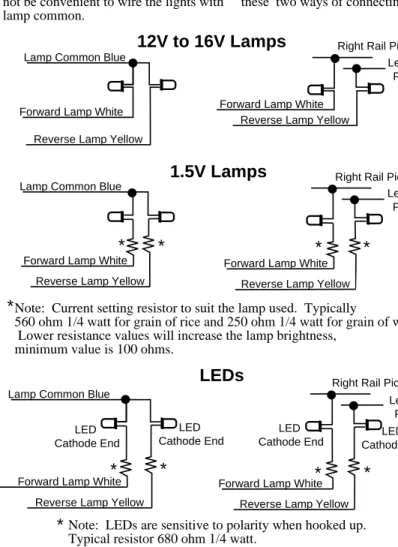
See Figure 2: Lamp Wiring Specificsfor details of wiring 12-16V lamps, 1.5V lamps and LEDs for use with and without the lamp common wire.
Right Rail (Engineer's Side)
Left Rail (Fireman's Side) Motor -Motor + Red Y e llow Blue Green W h it e Orange Gray Forward Light (F0 FWD) Reverse Light (F0 REV) Lamp Common (+RAW) Function 1 (F1) Function 2 (F2) Violet Right Side (Engineer's) Power Pickup Left Side (Fireman's) Power Pick-up DC BRUSH MOTOR (BRUSHES ISOLATED) Black Lamp For FX Operation OR Other Function Controlled Device -+ Note 1 Forward Lamp Reverse Lamp
Lamp Return Line
Function 3 (F3), etc. Brown
This side of motor was originally connected to the Right Side Pickup
This side of motor was originally connected to the Left Side Pickup
Digitrax Decoder
Reverse Lamp Yellow Lamp Common Blue
Forward Lamp White
Reverse Lamp Yellow
Forward Lamp White Reverse Lamp Yellow
Operation with Lamp
Common Connected Operation without Lamp Common Connected
Lamp Common Blue
Forward Lamp White Forward Lamp White
Reverse Lamp Yellow
1.5V Lamps
12V to 16V Lamps
Right Rail PickupLeft Rail Pickup Right Rail Pickup
Left Rail Pickup
Reverse Lamp Yellow Lamp Common Blue
Forward Lamp White Forward Lamp White
Reverse Lamp Yellow
Left Rail Pickup Right Rail Pickup
LEDs
LED Cathode End LED Cathode End LED Cathode End LED Cathode End Lamp brightness won't be affected byoperation of analog locos on the layout. This is the preferred wiring method but, in some locomotives (particularly in N-Scale and smaller HO units) it may not be convenient to wire the lights with lamp common.
Lamp brightness will change depending on the direction of the analog locomotive being operated on the layout. If you don't run analog engines on your layout, you won't notice any difference between these two ways of connecting the lights.
Note: Current setting resistor to suit the lamp used. Typically
560 ohm 1/4 watt for grain of rice and 250 ohm 1/4 watt for grain of wheat. Lower resistance values will increase the lamp brightness,
minimum value is 100 ohms.
Note: LEDs are sensitive to polarity when hooked up. Typical resistor 680 ohm 1/4 watt.
Transponder equipped decoders must be hooked up with lamp common connected for proper operation.
*
*
*
*
*
*
*
*
*
*
3.9 Installing Lighting Effects
Adding lights to your locomotives can bring an added degree of realism but there are a few things to consider.
Headlight and Rear Light Operation
Automatic headlight reversing: All Digitrax decoders are shipped with automatic reversing headlight operation as the default mode of oper-ation.
Manual headlight operation: If you do not want automatic reversing headlight operation most Digitrax decoders can be set up so that the white lead (forward light) operates on F0 (Function 0) and the yel-low lead (reverse light) operates on F4 (function 4) by programming CV61 to a value of 01 (or 03 if Transponding™ is also enabled).
FX & FX3light operation: If you are using a decoder with FX
func-tions refer to the Section 6.10 for details how to program the differ-ent FX effects.
Additional Lamp and Function Wiring Considerations Lamps with current draw over 50 mA:For regular 12 to 16 Volt lamps
that draw more than 50 mA when lit, we recommend that you put a 22 to 33 ohm 1/4 watt resistor in series with the lamp leads. This will ensure that the lamp "start-up currents" (which can be up to 10 times normal current draw) do not overload the outputs.
For decoders with FX
3functions, if you can control the
functions but not the motor, this indicates that the motor
is not properly isolated from the frame. Once you
cor-rect the problem, the decoder will work normally
For decoders with FX functions, the first time you apply
power to a Digitrax decoder equipped loco, if the lights
blink on and off, there is a short in the installation!
Remove the loco from the track immediately.
Review the wiring and correct the short before
Loco with only one lamp:If the locomotive has only one lamp, connect both directional light outputs (white & yellow) together. In this case the single light will be on if the F0, the light function, is turned ON.
Connecting additional function outputs: Connect F1-F6, the other function outputs to the functions you wish to control. Be sure not to exceed the total output current rating of the function outputs for the decoder you are using (125 mA for DZ & DN series & 200 mA for DH series and 1 Amp for DG series).
Transponder equipped decoders: When you install a wired transpon-der equipped decotranspon-der, you should also install a load resistor of between 270 ohms & 470 ohms between the blue and white decoder leads to ensure proper transponding operation. You may see a slight glow even when the forward light is turned off because of the way transponding works. See Section 6.15 for more information.
3.10 Final Decoder Test
Once the decoder is installed, you are ready for the test track.
For decoders with FX functions, if you notice the loco’s lights flashing on and off when you first power up the loco, remove it from the track immediately. When the loco’s lights flash at power on, it is an indication of a short circuit in the decoder installation which must be corrected before proceeding.
For decoders with FX3functions, if you are able to control the loco’s lights but
the motor will not run, this is also an indication of a motor short circuit that must be corrected.
1. Run your Digitrax decoder equipped locomotive on a regular DC track with the positive polarity connected to the right side wheels. The Digitrax decoder in the locomotive will recognize that it is not receiving DCC commands and automatically convert to analog mode.
2. Using your throttle, command the loco to move forward. If the loco moves in reverse, the input power feeds to the decoder are reversed. Power down, swap the decoder power input connections (red & black leads) and try again.
3. Next, run the decoder equipped loco with your Digitrax system. Follow the instructions in your Digitrax Starter Set manual to select and run the locomotive. Operate any other functions installed to be sure they can be turned on and off. Since you have not programmed the decoder yet, the decoder will use the factory default settings.
4. The decoder's address is set to 03, the headlights are set up to be auto-matically reversing and all other variables are set up so that the loco will run with no acceleration or deceleration.
5. If any problems are observed check your wiring and re-test.
4.0 Troubleshooting
4.1 The decoder won't respond
Is the loco on powered track? If the throttle is indicating that track power is off, turn track power on. For DT100, DT200 & DT300 press RUN/STOP and the + UP ARROW key to turn on track power. For DT400 press PWR followed by the Y+ Key to turn track power on.
Can you select the loco on your throttle? If not, the loco may be use by another throttle or it may be part of a consist (do you see a cn in the display when you try to select it). You will need to release the loco from other throttles or remove it from the consist to be able to run it on your throttle.
Do the settings in CV29, the configuration register, match the com-mand station output?If your decoder is a 14 step decoder running on a system that is sending 28/128 speed step commands, status editing will be needed to make the commands sent by the system match what the decoder is expecting.
Have you reset any CVs since the last time you ran the loco? If so, go back and change them to their default values and then try to run the loco. It is possible to set acceleration so high that it will take 10 minutes for the loco to start moving.
Does your throttle say 'xFF' or “slot=max”?This means that the sys-tem's capacity to handle operating locos is full. The DCS50 that comes with the Zephyr can run up to 10 locos. The DB150 that comes with Super Empire Builder can run up to 22 addresses at the same time. The DCS100 that comes with Super Chief Sets can han-dle up to 120 addresses at the same time. The DCS100 is set for 22 addresses at the factory, consult your Super Chief Manual for infor-mation on changing this to 120 if you are exceeding the limit often during operations. If you have the FF or slot=max message, be sure that all locos that are not running are released from throttles. During decoder programming, the FF or slot=max message may also be displayed if the loco you are trying to program has too many
loads attached. If this is the case, you need to remove some of the extra loads to allow the decoder to be programmed. This happens most often with locos that have many lamps installed or where the lamps are wired directly to the track pickups.
Was the loco running and then suddenly stopped?If the decoder is very warm it may be in thermal shutdown. Let it cool off and see if it starts again. Also check for localized track problems.
Are there burn marks on the decoder? You'll need to send it in for repair!
Is this the first time you powered up the decoder after installation? If it is a decoder with FX functions, are the lights flashing?If so, remove the loco from the track immediately and check your installa-tion for motor isolainstalla-tion and short circuits.
Is this the first time you powered up the decoder after installation? If it is an FX3decoder, can you control the functions but not the motor?If so, remove the loco from the track and check your instal-lation for motor isoinstal-lation or short circuit problems.
If all else fails, reprogram the decoder’s address and reset CVs to default values.
4.2 The decoder runs for a while & then just stops
The decoder may be overheating. Is the decoder very warm to the touch? It is normal for decoders to warm up while in use but they should not be hot to the touch. Be sure the decoder is installed so that it can shed heat. Don't put decoders near the motor or lights.
4.3 Loco operation is jerky & erratic
Is the track clean and are the power feeds reliable? Are the locomotive wheel pickups and internal electrical connections reliable? The majority of intermit-tent operation faults can be traced to bad connections and poor or noisy wheel pickups on locomotives. Check track cleanliness and quality of wheel pickups.
4.4 "Strange" locomotive light operation
If you can't control the operation of the lights in your locomotive with your throttle (in default 128, or 28 speed step mode), be sure that the decoder is programmed for advanced 28 speed step mode. Your Digitrax decoder was shipped programmed to 128 speed step mode. You may have changed your decoder's programming when performing the decoder test procedure. In any case, if you are not able to turn the locomotives lights on and off, you will need
to change CV 29 to 006/x06 to have proper light operation when using your Digitrax system in its optimum 128 speed step mode. Do this by programming CV29 with a value of 006/x06 (See Section 6.2 for more information about CV29.)
If you can't turn the lights on and off or the lights blink when you run the loco, this is symptomatic of a Standard (14 speed step operation) decoder trying to process 28 speed step Advanced packets.Be sure that the decoder and command station are using the same mode by reprogramming the decoder or by changing the command station's operating mode.
4.5 The locomotive won't move at all
Does the locomotive have any mechanical binding problems? Are any wires shorting or touching moving parts? We have had several locos in for service that actually had tape on the moving parts that prevented the engines from moving and nothing was wrong with the decoders.
When you are operating a Digitrax Command Station set up to run in 128 speed step mode, there are some decoders that only understand 14 speed step mode. If you are using one of these non-Digitrax decoders, you will need to status edit the decoder so that it will run.
4.6 Locomotive "buzzes"
Most noisy locomotive issues are caused by vibrations inside the loco’s mecha-nism. For DCC equipped locos, try lubricating the locomotive's brushes and tuning up the loco’s mechanism.
Analog locos (without DCC decoders) make a "singing" sound when sitting still on DCC layouts. This noise decreases as the analog loco is accelerated. The noise is caused by the DCC track signal. You can significantly reduce this noise by using conductive brush lubricants and by assuring that there is no vibration inside the loco that will add to the noise generated. When operating analog locos on DCC layouts, it is best to park them off the live track unless they are running. This will prevent heat build up, minimize the humming noise and lessen stress on the motors.
4.7 The Quarter Trick
If your track does not have adequate power supply to the locomotives, then the DCC signal won't get through either. Take a quarter or screwdriver blade and go around your layout creating electrical shorts every 10 feet. Your DB150 should beep and shutdown when the short is present. When the short is removed, the booster should return to normal operation. If this does not hap-pen, then you need to add more feeders.
4.8 The LT1 tester
Check your LocoNet cables with the LT1 tester to be sure the cables are good. See Section 3.5 for complete instructions.
4.9 Getting Help
If you have installed a decoder, read the manual and still just can't seem to get it to work the way you think it should, let us know! Often your local Digitrax dealer will be able to help you work out any problems you may encounter. If not, please contact Digitrax directly. Our support staff is available Monday through Friday to help you with your questions. You can call (850) 872 9890, fax (850) 872 9557 or e-mail [email protected]. We also maintain a web site, www.digitrax.com, that has the answers to many commonly asked questions. So, don't suffer in silence! There is no such thing as a "dumb ques-tion!"
5.0 Decoder Programming
5.1 What are CVs?
Your Digitrax Decoder has many different configuration variables, or CVs, that let you set up many different operating characteristics for each decoder installed in each locomotive to give you prototypical operation.
Each CV controls an operating characteristic of the decoder based on the CV value that you program for the CV. You can pick and choose from among the CVs and program each one independently or you can use the default CV values that are pre-programmed at the factory. Once these CV values are programmed, they are "remembered" in the decoder until you reprogram it with a new value. Before you start programming your decoders, it's a good idea to run your decoders with the default values that come pre-programmed from the factory. This will let you get used to using DCC before you begin customizing. In many cases, you will find that you only need to change the address of the loco-motive to have great operation. If you decide to use deceleration, in particular, keep the programmed CV values small so that you have time to adapt to the delays in deceleration you have set up without crashing your valuable locomo-tives!
5.2 Programming Modes: Paged, Physical Register, Direct & Ops
Digitrax systems default to the "paged" programming method. Paged program-ming is the most commonly used programprogram-ming method and is the Digitrax pre-ferred method for programming.
Genesis II, using a UT2 & DB150, supports paged programming exclusively. The UT2 throttle can program CVs 01-99 to values of 000-099. All UT2 pro-gramming is done with decimal values. See Appendix B.
Zephyr, Super Empire Builder, & Super Chief let you choose from paged, physical register or direct programming methods. This gives you maximum flexibility to program all DCC decoders. You can also access operations mode
programming which lets you program decoders that support this feature while the locomotive is on the mainline without having to put them on the program-ming track. DT300 & DT400 series throttles can use either decimal or hex-adecimal values for programming. See Appendix B.
DT100 programming is done with modified hexadecimal numbers for selecting CV#s and hexadecimal values for entering CV Values. See Appendix B.
Note: You can program the decoder address with Ops mode programming with the DT300 & DT400 series throttles. DT100 series throttles cannot program the address with Ops mode programming.
Physical register mode is a very basic and somewhat limited mode for pro-gramming decoders. With "register mode" you can program CVs 01, 02, 03, 04 & 29 only. Paged and direct programming give access to all CVs and appear very similar to the user. They are just two different methods for programming. All of these methods are included in the DCC industry standards.
DCC compatible command stations made by different DCC manufacturers han-dle programming in many different ways. The NMRA’s “Standards and RPs”, which are a small part of the DCC industry standards, allow for several differ-ent programming modes. All of these may or may not be supported by your command station or programmer. For the specifics and mechanics of program-ming with your system, please check your command station or programmer manual.
5.3 DCC Outputs For Programming & Train Operation
The DB150 that comes with Super Empire Builder, has one DCC output that is used both to run the trains and to program decoders. For this kind of command station, you will have to shutdown layout operations to program. Both the DCS100 that comes with the Super Chief and the DCS50 that comes with Zephyr have two DCC outputs. This means that you can program and read back decoders without having to shut down the layout. Both single and dual DCC output systems require a programming track.
5.4 Reading & Writing CVs
The DB150 Command Station has a "write only programmer," it will program CVs to the values you choose. DB150 will not read back CVs and their values programmed into your decoders.
The DCS100 & DCS50 Command Stations are "read/write programmers," they can program decoders and read back their CVs and values.
Another programming option is to use a PR3 programmer and your computer to program and read back decoders. Other DCC compatible programmers are able to program Digitrax decoders as well. Consult the manual for the system you are using for complete programming instructions.
Digitrax FX3decoders have operations mode readback capabilities when used
on layouts instrumented for this feature.
Note: According to NMRA “RP 9.2.3” you are “required” to use a low power setting for all decoder programming. Digitrax recommends that you use low power programming for initial decoder tests prior to installation in the locomo-tive. Digitrax does not feel that it is necessary to use a low power setting for decoder programming once you have successfully installed the decoder in the locomotive. If you are reprogramming an installed decoder, feel free to follow the steps presented here. If you wish to use a low power setting for decoder programming, please see the decoder initial test procedures which detail the use of a protection resistor to provide a low power programming option.
6.0 Configuration Variables
As discussed in Section 5.1, Configuration Variables or CVs are special storage locations or "pigeonholes" in the decoders. By programming CV values into CVs you can customize each decoder's performance characteristics. These characteristics are permanently "remembered" by the decoder even when the power is off! The CVs you program can be changed as often as you like. The meaning of most CVs is defined by RP 9.2.2. There are also some manufactur-er specific CVs that are defined by each manufacturmanufactur-er to accommodate their own special features.
At first glance, you will see that there are many different CVs. This may seem confusing but, don't worry, Digitrax decoders are shipped with a set of pre-pro-grammed factory default values that let you get up and running right away. As you begin to explore the possibilities with DCC, you will probably reprogram CV01, the decoder's address. This lets you run more than one locomotive at a time. You may need to make changes to CV29, the "configuration" CV to make your lights operate correctly. Next you may decide to set up acceleration (CV03) and deceleration (CV04) or you may wish to set up your FX options using CVs 49 through 63 As you explore more of the capabilities of your decoder and system refer to TABLE IIas a guide.
6.1 Decoder Addresses
The decoder's address is the identification number programmed into specific decoder that lets that decoder recognize commands sent to it by the command station. Once you program the decoder's address, it will be remembered in the decoder until you re-program it.
Decoders can be set up with both 2 digit and 4 digit addresses but only one or the other will be in use at any time.
You can change the decoder address by reprogramming it at any time so, you can set up any numbering scheme you choose for your locos. Many people assign the last two numbers of the loco's road number as the decoder address. You can program more than one loco to the same address. This is useful if you want to set up a basic consist and run several locos on a single address.
The Range of Digital Addresses
Address "00"is reserved for analog operation. All Digitrax command stations give you easy access to analog operation so you can run a locomotive without a decoder on the same track where you run your DCC equipped locos.
Addresses from 001 to 127(In hex, that’s x01-x99 for addresses 01-99 and xA0-xC7 for addresses 100-127) are the two digit address range. All Digitrax decoders have two digit address capability.
Addresses from 0128 to 9983are the four digit address range. All cur-rent production Digitrax decoders also offer four digit address capa-bility.
Two digit decoder addresses are set up by programming CV01 & CV29. Four digit decoder addresses are set up by programming CV17, CV18 & CV29.
6.1.1 Decoder 2 Digit Address: CV01
The 2 digit address is the short identification number for a spe-cific decoder. It is programmed in CV01. When you access CV01 with DT100 throttles, the
display will show “Ad”, instead of “01” when you dial up CV01 to program the 2 digit address. Ad stands for Address. Simply dial in the address number you want to program complete the programming sequence described in your starter set manual.
On your DT300 & DT400 throttles, the display will show Ad2 for two digit addresses and Ad4 for four digit addresses. All other CVs are displayed as numbers on Digitrax throttles. Be sure that CV29 is programmed to a value that has either "0” or “1" as the first digit to enable 2 digit addressing. See CV29 below for more information.
6.1.2 Decoder 4 Digit Address: CV17 & CV18
The 4 digit address is the long address for a specific decoder. It is programmed in CV17 & CV18. CV18 is the first two digits and CV17 is the second two digits of the address. Simply programming CV17 & CV18 will not enable 4 digit addressing. The DCS50, DB150 & DCS100 Command Stations that come with Zephyr, Super Empire Builder and Super Chief Sets provide automated programming that makes this process simple. See the starter set manuals for step by step instructions for setting up and enabling 4 digit addresses in your decoders.
6.2 Configuration Register: CV29 6.2.1 Characteristics Controlled by CV29
Configuration Variable 29 (CV29 for short) is a very special CV. The value entered for this CV controls several things:
1. 2 digit addressing or 4 digit addressing (as described above 2. Normal Direction of Travel (NDOT)
3. Speed step control: Advanced Mode (28/128 speed steps) or Standard Mode (14 speed steps)
4. Analog mode conversion On or Off 5. Speed table On or Off
The Normal Direction of Travel, or NDOTfor short, lets you set up your locos to run either long hood forward or short hood forward. Because with DCC the decoder determines which way the loco will move independent of track polarity, you can set up either direction as forward depending on the pro-totype. (Not all decoders have this feature so be sure to check the card that came with your decoder.)
There are two modes for speed step control: Standard or 14 speed step mode
and Advanced or 28/128 speed step control.
Because of differences in the capabilities of DCC compatible command sta-tions and decoders, you may have to set CV29 in your decoders to different values to match the mode of the command station you are using. If your com-mand station is sending standard 14 speed step mode comcom-mands, your decoders
must be programmed for standard mode in CV29. If your command station is sending advanced 28/128 speed step commands, your decoders must be pro-grammed for advanced mode in CV29. All Digitrax decoders are 128 speed step capable and we recommend that for best performance you run them in 128 speed step mode. If you are using non-Digitrax decoders that are not able to be programmed for advanced mode and you want to run your command station in advanced mode, you can "status edit" the standard decoders so that they can be run with your command station. See your starter set manual for the specifics of status editing.
The analog mode conversionfeature is very convenient if you plan to run your Digitrax decoded locomotive on regular DC layouts. With analog mode conversion enabled, the decoder will automatically begin operating as a DC locomotive when no DCC signal is detected by the decoder. This means that if you place your Digitrax decoder equipped loco, with analog mode conversion enabled, on a regular DC layout, it will run on the DC layout. Disabling ana-log mode conversion can be useful too as the following example illustrates:
Brake Generator Example:If you disable the analog mode conversion feature in a decoder, when DC power is present the locomotive will stop. This gives you a very inexpensive way of generating a "brake section" for stopping DCC locomotives in front of red signals. By NOT allowing analog conversion in the decoder, a relay can supply DC voltage to a track section in front of a red sig-nal to slow and stop a locomotive in the brake section. When the sigsig-nal turns green, the relay can restore the DCC track signal, and the locomotive will restart. The decoder will slow to a stop and restart at its programmed decelera-tion and acceleradecelera-tion values. In addidecelera-tion, if you are using a decoder with FX functions with CV13 programmed to keep functions running on DC, the loco's lights and functions will remain active when stopped on the DC brake section as long as DC power is supplied to the track while the loco is stopped! You can use your DCS100’s second DCC output to set up a braking section. See our website www.digitrax.com application notes and technical information page for instructions for setting up a braking section with DCS100.
Loadable speed tablescan be enabled or disabled with CV29. Speed tables are used to customize the throttle response curve of each decoder equipped locomotive. The speed table values can be stored in the decoder and then the table can be turned on or off with CV29. See the section on CVs 65-93 below for a complete description of how speed tables work.
6.2.2 Determining CV Value To Program Into CV29
The value you will program into CV29 will affect many important decoder characteristics. Each of these characteristics is controlled by a "software switch." This switch is either on or off depending on the CV value
pro-grammed. Following are two methods to determine the value to program into CV29.
The Addition Method
The table below shows each switch and its value if it is on or off. Notice that if the switch is off the value is zero. To determine the value to program for your decoder just go down the list and add up the numbers for all the switches you want to set as ON.
CV29 Examples of CV Values:
All Digitrax decoders are shipped with a factory programmed value of 006/x06 in CV29. This gives the decoders the characteristics highlighted.
A value of 039/x27 programmed into CV29 will give you a decoder that has a normal direction of travel in reverse, operates in advanced 28/128 speed step mode, has analog mode conversion enabled, does not use a speed table and has 4 digit addressing.
active and 128 speed step information is received from the command station, the table is interpolated to generate 4 in-between steps to give full 128 step res-olution. Note that with some older Digitrax decoders, if 128 speed steps are sent by the command station then the 14/28 speed step and Loadable speed table selections are not used.
6.3 V-start: CV02
The start voltage, V-start, is the extra voltage added to the motor drive voltage at the first speed step. This adjustment allows you to compensate for the loco motor's efficiency. The range you can program for this CV value is from 000/x00 to 255/xFF. Each value incre-ment represents an increase of approximately 1/2% of the total motor drive voltage,
when a "straight-line" throttle response curve is used. The value of 255/xFF represents 100% motor voltage. In advanced 28/128 speed step mode, the V-start value is interpolated from the first speed step to the middle speed step or "mid" step, 15.
NOTE: Digitrax FX and later model decoders use V-start in 128 speed step mode and run loadable speed tables in 128 speed step mode. Other standard and most non-FX decoders disregard V-start in 128 speed step mode and run loadable speed tables in 14 or 28 speed step mode.
6.4 Acceleration Rate: CV03
Acceleration is the rate at which the decoder increases from one speed step to the next in response to a new command to increase speed. CV03, acceleration, lets you simulate train weight or inertia. The range of values for acceleration is 000/x00 to 031/x1F. Setting CV03 to a value of 00 generates an immediate response to a new command to increase speed. As you increase the CV value programmed into CV03, the rate of speed step change is approximately 1/10 second per increment in acceleration value.
For example, a value of 01 programmed to CV03 will cause the decoder to change at 1/10 second per speed step (using the 28 speed step range). This means that it would take about 2.8 seconds for the loco to go from stopped to full speed if you command the loco to go immediately to full speed by crank-ing up the throttle.
6.5 Deceleration Rate: CV04
Deceleration is the rate at which the decoder decreases from one speed step to the next in response to a new command to decrease speed. CV04, deceleration, lets you simulate locomotive braking action. The range of values for CV04, deceleration, is 000/x00 to 031/x1F. A value of 00 causes an immediate response to a new command to decrease speed. As you increase the CV value programmed into CV04, the rate of speed step change is approximately 1/10 second per increment in deceleration value.
For example a value of 01 programmed to CV04 causes the decoder to change at 1/10 second per speed step (using the 28 speed step range). This means that it would take 2.8 seconds to decelerate from full speed to stop if you com-manded the loco to go immediately to stop when it was moving at full speed.
6.6 V-max: CV05
Setting CV05, V-max or maximum voltage, specifies an exact voltage that is applied to the motor at the highest speed step Setting V-max to a lower value than 255/xFF allows you to limit the top speed of a locomotive. The range of available V-max CV values is 000/x00 to 255/xFF. A value of 128 applies 50% of total voltage to the motor at the highest speed step. A value of 255/xFF applies 100% voltage at the highest speed step.
For backward compatibility, CV05 values of 000/x00, 001/x01 & 255/xFF all mean 100% voltage at step 28. If V-Max is accidentally set below V-mid, the decoder will use the V-mid setting as V-max.
V-max is not available when loadable speed tables are in use. In this case, set the maximum voltage by programming speed step 28 as the max voltage. Note: Some Digitrax decoders are not able to set V-max in 128 speed step mode. If you encounter this problem, status edit the decoder to run in 28 speed step mode and you will be able to set up v-max.
6.7 V-mid: CV06
Setting CV06, V-mid or mid point voltage specifies an exact voltage that is applied to the motor at speed step 15 ( or speed step 7 in a 14 step system). The range of available V-mid CV values is from 000/x00 to 255/xFF. A value of 128 applies 50% of the total voltage to the motor at step 15 (28 speed system). A value of 255 applies 100% voltage at the middle speed step.
If V-start (CV02) is accidentally programmed to a CV value greater than that programmed for V-mid (CV06), the decoder will force the output voltage for all steps below the V-mid value to be fixed at the V-mid value. This is done to prevent undesirable operational effects.
If a value of 00 or 01 is programmed into CV06 (V-mid), the decoder assumes a "straight-line" throttle response curve is desired. In this case, the decoder will run as though V-mid were set at a value of 50% of total motor voltage.
Note: Some Digitrax decoders are not able to set V-mid in 128 speed step mode. If you encounter this problem, status edit the decoder to run in 28 speed step mode and you will be able to set up v-mid.
V-mid is not available when loadable speed tables are in use.
6.8 Factory Reset CV: 08
CV08 is the factory reset CV for all FX3decoders and also the Manufacturer
ID CV for all decoders.
To reset all CV values to their factory default, program CV08 to a value of 008/x08.
To reset all CV values except for 28 step speed tables to their factory values set CV08 to a value of 009/x09.
Note: Performing a factory reset will not affect the manufacturer ID and will reset the decoder’s address to the factory default of 03, a 2 digit address.
6.9 Analog Functions Enable/Disable: CV13
In FX3decoders, CV13 is disabled.
In FX decoders, the analog functions enabled CV, CV13 lets you define which functions are active when the decoder is operating on DC track power. If you want function outputs F0 forward and reverse and F1 through F6 to be active when on DC (for example when using a short DC track as "brake section") pro-gram CV13 for a CV value of 255/xFF. The factory default value for CV13 is 00, which turns OFF all functions when on DC track. Note that if analog mode conversion is disabled in CV29, it will NOT affect how CV13 controls the functions. Even though the motor will stop on DC power, the functions will still operate if CV13 is programmed for them to do so. To find the best settings for you experiment with the values until you get the desired settings.
To determine the value to program in CV13 add all the values for the functions you want to have ON during DC operation and use TABLE VIto convert the decimal number you came up with to the hex value you will use for program-ming:
For example 64+128+1+2+4+8=207 decimal or xcF hex will operate F0 for-ward & reverse, F1, F2, F3 & F4 functions on DC. To operate F0 Reverse and F0 Forward add 1+2=003 decimal or x03 hex.
6.10 Digitrax Special Light Effects: CV49-CV63 & CV113-CV116
Decoders with FX3features have 8 user configurable, independent special
effects generators. Decoders with FX features have 4. These are set up by pro-gramming CV values as described below.
Digitrax decoders offer five different types of function outputs: There are five types of functions available on Digitrax decoders:
Standardfunctions turn functions on and off. Digitrax decoders with standard functions offer head lights that can be set up to be either automatically reversing or individually controllable. If your decoder has CS, FX or FX3and you do not program the CVs to set up the
features, your function outputs will run as standard on/off function outputs.
Standard* functions turn functions on and off. These decoders offer automatically reversing head lights only.
Configurable strobe (CS)functions can be programmed with a limited number of simulated lighting effects similar to FX but without as many options. Use CVs 49 & 50 to set up the effects you choose for each function output. Configurable strobes are offered in those few Digitrax decoders where there was not enough "code space" to pro-vide full FX features.
FX functionsincorporate generators for prototypical lighting effects, like Mars lights, ditch lights, Gyralites, random flicker, single & double pulse strobes, etc. FX decoders offer up to 4 independent special effects generators.