Optimizing domain size and phase purity in all-polymer
solar cells by solution order aggregation and confinement
effect of the acceptor
Journal: Journal of Materials Chemistry C Manuscript ID TC-ART-07-2019-003697.R1Article Type: Paper Date Submitted by the
Author: 25-Aug-2019
Complete List of Authors: Zhang, Qiang; Chang Chun Institute of Applied Chemistry Chinese Academy of Sciences, State Key Laboratory of Polymer Physics and Chemistry; University of the Chinese Academy of Sciences
Chen, Zhenyu; Xi'an Jiaotong University, State Key Laboratory for Mechanical Behavior of Materials
Ma, Wei; Xi’an Jiaotong University, State Key Laboratory for Mechanical Behavior of Materials
Xie, Zhiyuan; State Key Laboratory of Polymer Physics and Chemistry, Changchun Institute of Applied Chemistry, Chinese Academy of Sciences, Changchun 130022, P. R. China,
Han, Yanchun; Changchun Institute of Applied Chemistry, State Key Lab of Polymer Physics and Chemistry
ARTICLE
Received 00th January 20xx, Accepted 00th January 20xx DOI: 10.1039/x0xx00000x
Optimizing domain size and phase purity in all-polymer solar cells
by solution order aggregation and confinement effect of the
acceptor
Qiang Zhang,
a,bZhenyu Chen,
cWei Ma,*
cZhiyuan Xie,
aand Yanchun Han*
aDomain size, phase purity, and the interpenetrating network within the active layer of all-polymer solar cells (all-PSCs) are crucial for efficient charge generation and carrier transport. However, it is a great challenge to decrease domain size and enhance phase purity simultaneously because of the energetically disfavoring polymer-polymer mixing and chain entanglement. In this work, we manipulated the domain size and phase purity of J51:N2200 blends by promoting their solution ordered aggregation and the confinement of acceptor N2200 to J51 during phase separation. Thus, three solvents, chloroform (CF), mesitylene (Mes), and cyclopentyl methyl ether (CPME) were selected. The solubility of J51 and N2200 in these three solvents decreases solubility differences between J51 and N2200 increases gradually. Among these three solvents, only in CPME solution, N2200 possesses ordered structures, which reduces nucleation barrier to increase nucleation density and boosts template effect of N2200. During phase separation, the ordered aggregation of N2200 dominates solid-liquid phase separation and has the confinement effect of J51. Thus, the blend films cast from CPME have fine-scale phase separation in contrast to the films from CF. In addition, the "memory" effect of ordered aggregations transferred to films can enforce the order of blend films. As a result, the blend film with small domain size (≈21 nm), interpenetrating network structure, and a higher degree of crystallinity was obtained by processed from green solvent CPME. The improved morphology facilitated charge-generating process and carrier transport, resulting in higher short-circuit current (Jsc), fill factor (FF), and the power conversion efficiency (PCE).
1. Introduction
Recently, the hotspots of bulk heterojunction organic solar cells (BHJ OSCs) research have focused on the non-fullerene acceptors (NFAs).1, 2 Indeed, impressive progress has made in
developing high-performance OSCs based on NFAs thanks to the synthesis of new materials3, advances in optical absorption
of engineering,4, 5 and manipulating the morphologies of active
layers.5-8 Among the NFA OSCs, active layers formed from a
polymeric donor and a polymeric acceptor, those are, all-PSCs.9, 10 With the potential for applications in flexible wearable
devices, all-PSCs have attracted considerable attention as they possess critical advantages such as durable morphological stability, high blend ratios tolerance, robust mechanical properties.9, 11-15 Up to date, all-PSCs have acquired significant
advancement with the devices performance exceeding 10% ascribing to the emergence of new synthetic polymers.16, 17 On
the downside, the performances of all-PSCs still lag behind the
polymer solar cells based on non-fullerene small molecular due to the difficulty in regulating the domain sizes and purities of phase separation.9, 18-21 Since the low entropic contribution to
the Gibbs free energy by the polymeric donor and polymeric acceptor that not thermodynamically conducive to polymer-polymer mixing, the large domain sizes near 50−200 nm in all-PSCs are very normal, leading to low short-circuit currents.19, 22-28 In addition, entanglement and low diffusion ability of polymer
chains reduce the ordering of domains, affording unfavorable charge transport. Simultaneously reducing domain sizes and elevating phase purity of the active layer in all-PSCs can effectively help for improving device performance.29
Intense efforts have been invested to regulate the morphology of the interconnected network in the active layer of all-polymer blends.20, 30-34 Normally, phase-separated
morphology manipulation in all-PSCs can be realized by means of compatibilizers,35 side chain optimizations,36-38 crystallinity
control via regulating backbone structure,39 molecular weights
manipulation for donor and acceptor polymers,40 and
ameliorating device processing technology.41 However,
reducing the domain size can negatively impact on the PCE when the decrease in domain size comes at the expense of reducing the ordered stacking of molecules concomitantly. Reducing domain sizes and elevating phase purity at the same time seem to be stumped as these morphology parameters always keep a competitive relationship in the regulatory process. Promoting polymer aggregation conformation in the a.State Key Laboratory of Polymer Physics and Chemistry, Changchun Institute of
Applied Chemistry, Chinese Academy of Sciences, 5625 Renmin Street, Changchun 130022, P. R. China. E-mail: [email protected]
b.University of the Chinese Academy of Sciences, No. 19A Yuquan Road, Beijing
100049, P. R. China
c.State Key Laboratory for Mechanical Behavior of Materials, Xi’an Jiaotong
University, Xi’an 710049, P. R. China. E-mail: [email protected]
Electronic Supplementary Information (ESI) available: [details of any supplementary information available should be included here]. See DOI: 10.1039/x0xx00000x
ARTICLE
Journal Name
2 | J. Name., 2012, 00, 1-3 This journal is © The Royal Society of Chemistry 20xx
solution has a positive influence on decreasing phase-separated domain sizes and increasing the crystallinity in BHJ polymer solar cells containing small organic molecules.42-45 But for
all-PSCs, it remains controversial whether promoting solution-state polymer aggregation can have a positive impact on the morphology.46, 47 How the donor and acceptor polymers
aggregation in solution to regulate the domain sizes in all-PSCs remains less understood. Up to now, successfully controlling the degree of phase separation within 20-30 nm and improving domain purity in all-PSCs at the same time are less realized. The suboptimal film morphology with large domain sizes and low phase purity limits the improvement of device performance. Besides, to move toward the targets for applications in future, capitalizing on environmental-friendly solvents to substitute chlorinated solvents is often necessary.48
Based on the above considerations, herein, we propose to facilitate order aggregation in the solution to increase nuclei density and the template effect of the acceptor, leading to direct the phase-separated morphology and phase purity. We chose
poly{4,8-bis(5-(2-hexyldecyl)-2-yl)benzo[1,2-b:4,5-
b′]dithiophene-co-4,7-di(thien-2-yl)-5,6-difluoro-2-octyl-2H-benzo[d][1,2,3]trazole} (J51)49, 50 as the polymeric donor with
the poly{(N,N′-bis(2-octyldodecyl)-1,4,5,8-naphthalenedicarboximide-2,6-diyl)-alt-5,5′-(2,2′ bithiophene)} (N2200) 51, 52 being electron acceptor, see Fig. S1. Manipulating
the aggregation of polymers can be achieved through three different processing solvents of the halogen chloroform (CF), halogenated aromatic mesitylene (Mes), and non-halogenated and non-aromatic cyclopentyl methyl ether (CPME)48, 53 (structures are shown in Fig. S2). The solubilities of
polymers in the three solvents decrease gradually and the relative solubility differences between donor and acceptor polymer increase. The order aggregation of polymer would induce nucleation and slow chain diffusion and then form network serving as a template for preventing large-sized phase domain formation. The relative solubility differences can enhance the effect of templating. Inducing nucleation can also enhance the polymer crystallinity. Through promoting the aggregation of polymer in solution, the phase-separated domain sizes of J51:N2200 blends from CF to CPME were greatly reduced, and the ordering of polymer and domain purity were also enhanced. Thus, the device performance was improved from 5.54% to 7.03%. Our finding demonstrates that promoting solution aggregation, especially, the ordered structures of N2200 can effectively optimize morphology of all-PSCs.
2. Results and discussion
In this work, we demonstrated order aggregations of both donor and acceptor polymers in solution make a vital role in well tuning the domain size and phase purity. The CF, Mes, and CPME solvents were utilized to control the solubility of polymers to promote the formation of ordered aggregations and the template effect of acceptor and then to optimize the morphology of blend films. We first discuss the molecular aggregation conformation of polymers in solvents and its
effects on the morphology of neat films. The ordered aggregates that promote nuclei and the template effect of the acceptor can facilitate the formation of small domains in the active layers. The favorable morphology with small domain and high phase purity canbe realized by CPME, making the optimal device efficiency of 7.03%.
2.1 Tuning aggregation of polymers in solutions via solubility
Polymer molecular aggregation in the solution state is supposed to be an operative precursor to crystallinity, domain purity, and phase separation. The molecular aggregation conformation in the solution depends heavily on solvent quality. As to modifying the aggregation of polymers, we have chosen three different quality solvents, halogen CF, halogenated Mes, and non-halogenated and non-aromatic CPME. Polymer aggregation in solution is linked to the polymer solubility in the solvent. To confirm the quality of the solvents, we first performed solubility tests of J51 and N2200 in the three solvents, using ultraviolet-visible (UV−vis) absorption to measure the quantitative solubilities (seen in Fig. S3 and Table S1). The donor polymer J51 showed good solubility in all three solvents, while the solubility gradually decreased from CF, Mes to CPME. The solubility of N2200 showed the same regularity, N2200 dissolved poorly in the CPME. The solubility differences between J51 and N2200 in the three solvents progressively increased. For studying the impact of solubility on the aggregation behaviors of polymer chains in solutions, we measured the UV-vis spectra of J51 and N2200 with a consistent concentration (0.1mg ml-1) in various
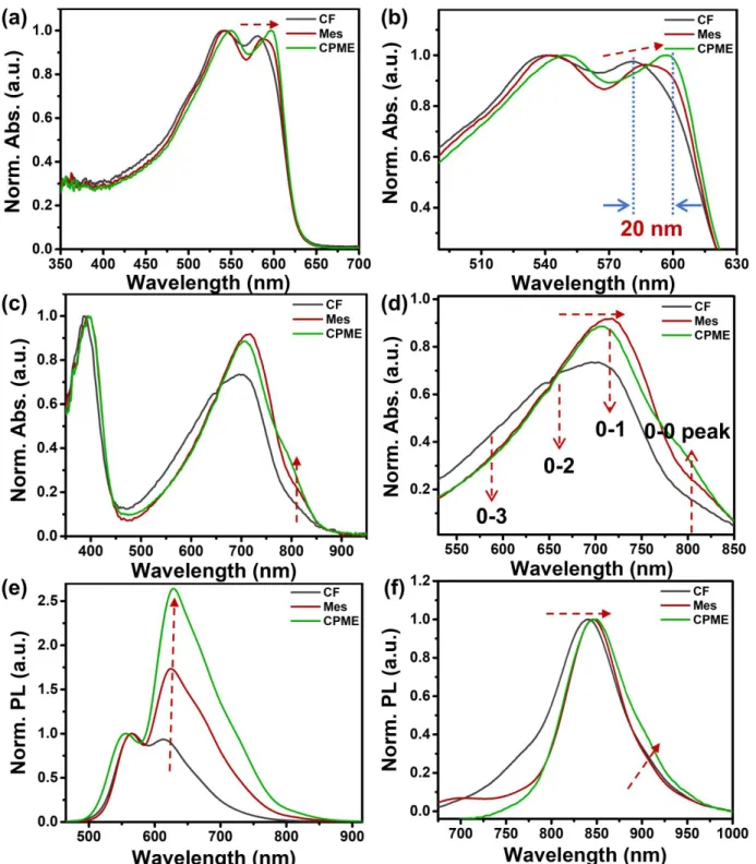
solvents. Fig. 1 presents the normalized solution UV–vis absorption spectra, (a) (b) for J51 and (c) (d) for N2200, respectively. J51 shows two distinct absorption peaks between 450 nm and 650 nm in all solvents.50 For the three J51 solutions,
two absorption peaks gradually bathochromic shift with the decrease of solubility. The absorption peaks’ position of J51 exhibits considerable variations as the solvent changes. Comparing the CF and CPME solutions, the low-energy absorption peak redshift ~10 nm and the high-energy absorption peak redshift ~15 nm, respectively. These results show that the polymer chains of J51 aggregation increased gradually in solutions as the solubility dropping off. The redshift in solution state indicates that the ordered structure of polymer chains has already formed in the solution phase. Fig. 1 (c), (d) depicts the UV–vis absorption spectra for N2200 solutions. The N2200 has two absorption regions where a short-wavelength peak (≈400 nm) is ascribed to π–π* transition, and the broad long-wavelength peak (500–900 nm) derives from the intramolecular charge transfer transition. On decreasing the solubility from CF to CPME, two absorption bands continuously redshift to longer wavelength region. The N2200 aggregate absorption presents a red-shifted trend as the aggregates contain the polymer chains with planar conformations. Interestingly, the shoulder peak at 810 nm in CPME solution enhanced much more than that in CF and Mes solutions. These changes in the absorption spectrum indicate that the portion of aggregated N2200 polymer chains in the solution increases from CF solution to Mes, and then CPME solutions. CF is a good
Fig. 1 Normalized UV-visible absorption spectra and absorption peak position changes highlight of (a) (b) J51, (c) (d) N2200 in various solvents. Normalized photoluminescence (PL) spectra of J51(e), N2200 (f) in various solvents.
solvent for N2200, and chains form “aggregate I” in it. Previous work has confirmed that solvents with low polarizability, like toluene, promote the extensive aggregation and, N2200 chains form “aggregate II” in them, leading to the shoulder peak at 810 nm becoming more obvious.54 The absorption spectra of Mes
solution resemble that of the toluene solutions and N2200 aggregates even more strongly in CPME. Thus, we assume that the N2200 polymer chains in Mes and CPME solutions possess the characteristic features of aggregate II. From the UV−vis
analysis, both the donor J51 and the acceptor N2200 more
aggregate in solutions, and molecules adopt more planar conformations in the aggregation with the decrease of solubility. To have deeply understood the aggregation characteristic of J51 and N2200 in the three solvents, we further studied the solution-state normalized UV−vis spectra on the function of a series of temperature.41, 55 As depicted in Fig. S4,
we noticed that the feature peaks of polymer J51 gradually exhibited blueshift in all the three solvents with the temperature gradually rising from 20℃ to 60℃.It indicates that increasing temperature can break the aggregation of J51 in the solution.
Journal Name
ARTICLE
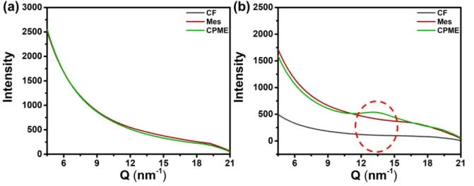
Fig. 2 Transmission wide-angle X-ray scattering of (a) J51and (b) N2200 in various solvents.
But for N2200, the changed are quite different compared to J51. In the CF solution of N2200, the low-energy peak moved to high-energy region and the intensity obviously decreased, which reflects the weak aggregation behavior of N2200 in the CF solution. For the Mes and CPME solutions of N2200, the high-energy absorption peak around 710 nm still remained as increasing temperature to 60℃, meanwhile the characteristic peaks at 810 nm are still obvious even at the temperature of 60
℃. The aggregation behavior of N2200 in Mes and CPME solutions under the influence of temperature is less weak. Compared to the three N2200 solutions, the range of variation of temperature-dependent absorption spectra with the order of CF > Mes > CPME, showing the aggregation in the CPME solution is strongest. As explained in previous work, absorption and photoluminescence (PL) spectra origin from different interactions: the interchain interactions have a greater influence on absorption while the intrachain make more interactions on photoluminescence.56 In the normalized PL
spectra of the J51 and N2200 solutions shown in Fig. 1(e-f), we can observe similar changes. As for the J51 solutions, the PL spectra of the solutions present two peaks. Going from CF to CPME solutions, the emission peak at lower energies is issued in a pronounced redshift. Such changes demonstrate that increasing the conjugation length can make an enhancement of the π−π* interactions.57 The intensity of the second peak at
lower energy (around 620 nm) relative to the high energy peak (around 550 nm) increases with decreasing solubility. This change results from the polymer chains getting more ordered and planarized within solutions. In the PL spectra of N2200 shown in Fig. 1(f), we observe one dominant peak at around 840 nm, the emission peak features a redshift along with the solubility reducing. This is in analogy to absorption spectra. Besides this change, a shoulder peak around 910 nm arises in the PL spectrum of the CPME solution. This is complementary to the behavior of the lower energy peak observed in corresponding absorption spectra. According to the PL spectra of N2200 in various solvents, the associated vibrational structure and a red shift indicate the formation of more ordered and longer conjugation length polymer chains.
Besides the previous results, transmission wide-angle X-ray scattering (WAXS) characterizations have been performed for J51 and N2200 solutions. The corresponding profiles are shown in Fig. 2. No differences in the profiles of J51 can be seen with changing solvent. Due to the solubility of J51 polymer in all solvents being good and low concentration used to measure, there is no scattering intensity difference. For N2200 solutions, the scattering intensity increases from CF to CPME. N2200 aggregates strongly and exhibit weak π stacking in CPME solution. In other words, short-range ordered structures exist in the aggregation of N2200 in CPME solution.
The polymer conformation and aggregates in solution are crucial parameters affecting the morphology of the thin film. Previous study has suggested that the polymer solubility in the solution could impact the formation of nuclei. Classical nucleation theory can be used to determine the minimum nucleus radius, revealing by the Gibbs free energy in equation (1).58 The critical radius can be obtained by equation (2).58
ΔG = LπR2ρSΔμ + 2πRγ1 + 2LπRγ2 (1)
R*= −2γ/ρSΔμ (2) Here, ρS expresses the number of polymers per volume. The
item of ρSΔμ <0 amounts to the chemical potential of aggregation per fiber volume, γ1 and γ2 present the surface
tension at the end points of the nuclei and at the sides of the nuclei, respectively.48 Janssen et al., have demonstrated that
reducing the solvent quality to decrease the solubility of a polymer in solution, leads to increase the crystallization driving force. As equation (1) (2) shown, the larger Δμ would reduce the crystallization barrier and decrease the critical radius, resulting in more nuclei formed.58 As we discussed above, both the J51
and N2200 molecules adopted more planar conformations and had longer conjugation length polymer chains and more aggregate in solutions as the solubility decreasing from CF to CPME. The aggregates of J51 and N2200 also got more ordered in the solution from CF to CPME, which was demonstrated by UV-bis, PL, and WAXS measurement. Therefore, we suppose that the J51 and N2200 can form more nuclei with decreasing the solubility during the formation of films. In the case where the total number of free polymers is constant, the increased amount of nuclei causes random crystallization all over the film,
This journal is © The Royal Society of Chemistry 20xx J. Name., 2013, 00, 1-3 | 5
Fig. 3 AFM topographical images (3×3 μm2) of the surfaces for neat films: (a) J51-CF, (b) J51-Mes, and (c) J51-CPME; (d) N2200-CF, (e) N2200-Mes, and (f) N2200-CPME. resulting in numerous smaller domains. To confirm the effect of the amount of nuclei on the morphology of film, we first studied the morphology of the single component J51 and N2200. The surface morphology of component J51 and N2200 films cast from CF, Mes, and CPME solutions were examined first via tapping mode atomic force microscopy (AFM), seen in Fig. 3, The CF processed J51 film has pronounced polymer aggregation structures due to less amount of nuclei and large diffusion capacity of the chain. The J51 film cast from the Mes solution has less obvious polymer aggregation structures than the CF. For the J51 film obtained from the CPME solution, the surface morphology gets more uniform, which arises from the enhanced polymer aggregates in the solution. The N2200 films processed from CF, Mes, and CPME have a similar variation. Both films processed by the Mes and CPME show a significantly finer microstructure, whereas films processed by the CF evidence relatively large aggregates. Both J51 and N2200 films display the more uniform and finer structures as the polymer ordered aggregation increasing in the solutions. The formation of more ordered polymer chains with longer conjugation length in solutions can facilitate more nuclei, which leads to smaller phase domains and finer microstructures in both J51 and N2200 films.
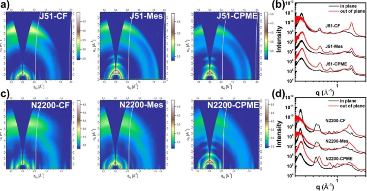
Next, we performed the two-dimensional (2D) grazing incidence X-ray diffraction (GIXD) for J51 and N2200 films to evaluate the polymer packing structures and crystallinity in the films cast from different solvents. Fig. 4a-b depict 2D GIXD images for the J51 and N2200 films prepared with different solvent, the related line cut profiles are shown in Fig. 4 c-d. As
shown in Fig. 4a, the J51 film cast from CF represents that scattering peaks of (010) along the out-plane direction (q=1.72 Å−1), and in-plane (100) diffraction peaks are mainly located at
q=0.25 Å−1, suggesting that the CF-processing J51 film tends to
have poor ordering. For the J51 films processed from Mes and CPME, noticeably enhanced molecular ordering is observed, despite the π–π stacking distance according to the out-of-plane (010) peak displaying a negligible difference with that of CF film. The film processed by CPME exhibits (h00) reflections up to the four orders along the qz direction and the film processed by Mes
has similar pattern. Obviously, the J51 polymer becomes more ordered in the films processed by Mes and CPME, which is evidenced by periodic out-of-plane (h00) reflections. In addition, we observed that the texture of J51 films processed by Mes and CPME exhibited dim (010) scattering peak in-plane implicating little edge-on the molecular orientation appearing. Since the longer time taken by the film-forming and the more aggregates in the solutions promote the polymer chains to assemble, Mes and CPME processed J51 films formed mixed face-on/edge-on textures, showing the formation of three-dimensional charge channels for efficient carrier transport in the film.59 For N2200 films, the (100) peak is located at 0.24 Å−1
and the out-of-plane π–π stacking peaks (010) are at q=1.58 Å−1,
1.61 Å−1, and 1.61 Å−1 are observed in all films, as shown in Fig.
4b. The corresponding π–π stacking distances are 3.98, 3.91, and 3.67 Å. The N2200 film processed by CPME presents (h00) reflections up to the four orders along the out-of-plane direction. That is to say, the N2200 film cast from CPME represents high order. The N2200 films prepared from CF and Mes show similar diffraction features, the absence of apparent (h00) reflections along the qz suggesting less ordered than
CPME. We have also performed absorption spectra for the corresponding films, as depicted in Fig. S5. With regard to J51, the film absorption spectra are a bit different from those of solution. The absorption spectrum of J51 film cast from Mes solution exhibits the most red-shift, followed by those of CPME and CF due to the boiling point of Mes is much higher than CPME and CF. It seems that the film order of J51 is influenced by thermodynamics and kinetics with kinetics dominating. For the film absorption spectra of N2200 cast from the three solvents, they show similar changes with solution-state absorption spectra. The intensity of peak at 810 nm gradually increases from CF to Mes, then CPME with showing the increased film order. The relative intensity changes of peaks around 700 nm for the N2200 films may be relevant to their specific molecular structure packing.
Journal Name
ARTICLE
Fig. 4 2D GIWAXS patterns of the (a) J51 films, (c) N2200 films spin-cast from different solvents and corresponding one-dimensional line-cut profiles of GIWAXS patterns for (b) J51 and (d) N2200.
2.2 Fine phase-separated morphology by ordered aggregation and template effect
Controlling nanoscale phase-separated morphology is one of the critical factors that determine exciton harvest efficiency and profoundly influences the device performance of all-PSCs. The phase separation process can be affected by multiple contributory factors combining of thermodynamic and kinetic factors. To study the phase-separated morphology of blend films spin-coated with CF, Mes, and CPME solutions, AFM and transmission electron microscope (TEM) measurements combining with resonant soft X-ray scattering (R-SoXS) were conducted to examine the effects of solution aggregation on domain size.
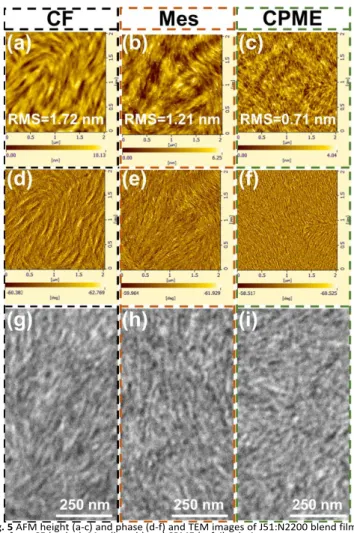
AFM topography and phase images of blend films from CF, Mes, and CPME solutions were obtained to examine the surface morphology. As shown in Fig. 5a-f, the surface root-mean-square (RMS) roughness is 1.72, 1.21, and 0.71 nm for the active layer cast from CF, Mes, and CPME. This result suggests that the surface topographies become smoother. The corresponding phase images also showed the same trend, the CF-processing leads to apparent aggregation phase feature, while the CPME-processing results to small and fine fibrous aggregates. The results indicate that promoting the aggregation of both donor and acceptor polymers in solutions can lead to well-defined nanofibrils feature with suitable domain sizes. To better understand the bulk morphologies of blend films, active layers were examined utilizing TEM, as presented in Fig. 5g-i. It is obvious to note that all the blend films formed the fibrillar network with the trends to be more extreme and finer from CF to Mes, and to CPME, which agrees well with the AFM morphology results. These structural changes may be due to the
increasing crystallinity and reducing domain sizes. The stronger polymer aggregation in solutions promoting generate more nuclei give rise to finer domain sizes and enlarged donor/acceptor interfacial areas, which is advantageous for exciton diffusion and carrier transport, benefiting for higher Jsc,
FF, and superior PCE.
We then analyzed the R-SoXS results for J51:N2200 blend films spin-coated from CF, Mes, and CPME solutions (Fig. 6). R-SoXS data were taken with a photon energy of 285.8 eV to obtain the maximum scattering contrast between the two polymers. The domain sizes of the J51:N2200 blend films can be calculated by an equation, ξ=2π/qmode. The mode domain size
stands for half of ξmode. The CF processed J51:N2200 blend film
has a peak at q=0.073 Å−1, thus representing a domain size of
43.0 nm. The J51:N2200 blend film spin-coated from Mes shows a peak at 0.075 Å−1, amounting to a domain size of 41.9 nm. The
J51:N2200 blend film processed from CPME displays the clear scattering peaks at q = 0.149 Å−1, meaning to a very small
domain size of 21.1 nm. Such small phase separation is well profitable for exciton diffusion and charges separation, leading to higher Jsc. Consequently, the trend of decrease in domain
sizes was found from CF to CPME samples. The relative domain purity through comparing the total scattering intensity (TSI) can be calculated from the scattering profiles. The domain purity underwent an adverse trend. The CF-processing film has the lowest domain purity and film from CPME has the highest domain purity, and the film obtained from Mes possess similar domain purity compared to CPME. The phase-separated domain size of blend film cast from Mes is close to that processed from CF, though J51 and N2200 are more aggregated in Mes solutions and the boiling point of Mes (b.p=166 ℃) is much higher than that of CF (b.p=61 ℃). As the domain size
This journal is © The Royal Society of Chemistry 20xx J. Name., 2013, 00, 1-3 | 7
Fig. 5 AFM height (a-c) and phase (d-f) and TEM images of J51:N2200 blend films cast from CF (a, d, g), Mes (b, e, h) and CPME (c, f, i) solutions.
of blend film correlates with the kinetics and thermodynamics of BHJ film development, the similar domain sizes between the CF and Mes samples are reasonable.
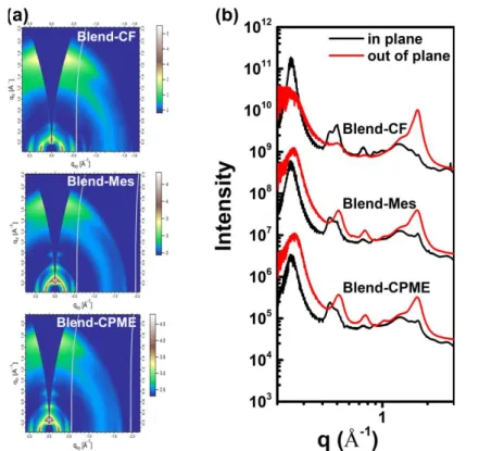
Next, we compare the polymer stacking properties of the blend films cast from various solutions. All the blend films presented evident (010) π−π stacking along the qz direction. The
lamellar packing distances of the blend films fabricated with CF, Mes, and CPME were 25.4 Å (q=0.25 Å-1). The corresponding π– π stacking distances were 3.66Å (q= 1.72 Å-1), 3.67 Å (q=1.71 Å -1), and 3.67 Å (q=1.71 Å-1), respectively. The blend films
prepared from Mes and CPME show stronger (h00) scattering peaks along the out-of-plane direction, indicating that J51:N2200 blend films can mostly maintain the molecular order of the neat J51 films, which is relevant to more noticeable molecular aggregation in Mes and CPME. These results agree with our previous analysis that the blend films processed from Mes and CPME had higher domain purity. Enhanced ordering would make a favorable role in the carrier transport and then would improve the efficiency of OPV devices.
2.3 Improving device performance via optimized morphology
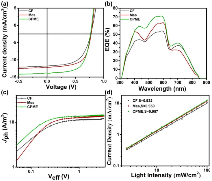
To ascertain the correlation between cell efficiency and active layer morphology, we evaluated photovoltaic current density-voltage (J−V) curves of the J51:N2200 devices cast from CF, Mes, and CPME. All devices were prepared in the glovebox adopting
a conventional conformation of ITO/PEDOT:PSS/J51:N2200 (2:1, w.t/w.t)/PFN-Br/Ag. Fig. 8 (a) displays the J–V profiles of the optimized devices fabricated from various conditions. Table 1 listed the detailed parameters. The device processed from CF shows a PCE of 5.54% with a Voc of 0.81 V, a Jsc of 11.83 mA cm−2,
and an FF of 57.87%, while the average PCE is 5.26%. The devices display a modest PCE due to the low Jsc, which results
from the large domain sizes and low phase purity. Compared with the device processed from CF, devices prepared with Mes yield a relative higher Jsc of 12.23 mA cm−2 because of the slight
decrease of domain sizes, with a Voc of 0.80 V, and an FF of
64.22%, a PCE of 6.28% (an average PCE of 6.0%). The significant improvements in FF could be ascribed to the reinforced domain purity. The minor decreased Voc is not uncommon due to the
improved order of blend films that causes energy losses. As the active layer prepared from the CPME solution, the highest PCE up to 7.03% with a Voc of 0.80 V, Jsc of 13.84 mA cm-2, and an FF
of 64.27% was obtained, which benefits from the enlarged donor/acceptor interfacial area available for exciton separation, and the high degree of domain purity available for carrier transport. Variances of Jsc due to changes in domain sizes and
phase purities are largely accountable to the changes in the general cell performance. The minor decreased Voc is not
uncommon due to the improved order of blend films that causes energy losses. The minor decreased Voc is not
uncommon due to the improved order of blend films that causes energy losses. The blend films using CPME as processing solvent presented both the smallest domain sizes and highest domain purity, therefore coming along with boosted Jsc and FF.
The trend of Jsc values with different solvents keeps pace with
with the changes in the external quantum efficiency curve (EQE), as presented in Fig. 8(b). The EQE curves demonstrated wide-ranging response between 300 and 850 nm. We noted that the
Fig. 6 R-SoXS scattering profile for J51:N2200 blend films processed from CF (black line), Mes (red line) and CPME (green line) as indicated.
ARTICLE
Journal Name
8 | J. Name., 2012, 00, 1-3 This journal is © The Royal Society of Chemistry 20xx
peak around 600 nm was slight blue-shifted by using CPME compared to the Mes-processed devices in the EQE profiles. It results from more crystalline and ordered J51 film cast from Mes (the results as shown in Fig. 4 and Fig. S5) for the much higher boiling point of Mes than CPME and the kinetics dominating the arrangement of J51 molecular during the longer film evolution time. The EQE peak values of the optimized device at 590 nm were around 71% for the device processed with CPME. The EQE of devices with different solvents well-matched with Jsc values. With the purpose of having a further
cognitive of photon absorption and exciton dissociation process in the active layers cast from different solvents, we studied the photocurrents density (Jph) in the wide-ranging biased voltage,
depicted in Fig. 8 (c). The exciton dissociation probabilities efficiency, P(E,T), can be determined by normalizing Jph (at the
short circuit circumstance) with Jsat (Jph/Jsat).60 The calculated P(E,T) values for the CF, Mes, and CPME three devices were 93.28%, 94.14% and 95.91%, respectively. Table S2 lists the detailed values. The CF processed devices had the lowest efficiency of the exciton dissociation due to the large domain size so that the CF devices generated the lowest Jsc. Therefore,
decreasing geminate recombination promotes the dissociation and generation of charge carriers, thus giving rise to a dramatic boost of Jsc. This well agrees with the Jsc data for these devices.
Besides, we also measured the J-V characteristics under various light intensity (P) to understand carrier recombination kinetics
for the devices, as Fig. 8 (d) and Fig. S6 shown. Quantitatively,
Jsc has a power-law function of light intensity (Jsc ∝Pα), and
linearity would suggest less charge losses during the carrier transport process.61, 62 The exponential factors of the three
devices were 0.932 for CF, 0.950 for Mes, 0.957 for CPME. It is apparent that the devices processed with Mes and CPME had the lower trap-assisted recombination. Consequently, the CPME devices had the highest FF. Efficient and balanced carrier transport within active layers is the assurance for high FF and
Jsc. To have deeper knowledge in the difference of FF in devices
cast from three solvents, charge carrier mobilities were determined applying the space charge limited current (SCLC) method via the hole-only and electron-only diodes. The related
J−V characteristics and SCLC fittings for the hole and electron devices are depicted in Fig. S7. Table S3 summarizes the calculated hole (μh) and electron mobilities (μe)in detail. The
calculated hole/electron mobilities of J51:N2200 were 9.13/1.64×10−5, 1.46 × 10⁻⁴/3.76 × 10−5, and 3.45 × 10⁻⁴/7.14 ×
10−5 cm2 V−1 s−1 for CF, Mes, and CPME samples, respectively.
As the enhancement of phase purity, both the hole and electron mobilities increase by degrees. Efficient and balanced charge carrier mobilities are necessary to reduce recombination, as observed for Mes and CPME conditions, helping to improve FF. Higher mobility carrier also helps improve the Jsc, thus the Jsc of
the Mes sample is slightly higher than that of the CF sample.
This journal is © The Royal Society of Chemistry 20xx J. Name., 2013, 00, 1-3 | 9
Fig. 8 (a) J–V curves, (b) EQE spectra, (c) photocurrent density (Jph) plotted function of effective bias (Veff), and (d) Jsc versus Plight for J51:N2200 solar cells fabricated using CF, Mes, and CPME.
Table 1. Photovoltaic characteristics of all-PSC devices based on J51:N2200 blend film processed with different solvents.
a Statistic values averaged from over 6 cells.
In all-PSCs, the domain size and phase purity within active layers are crucial for determining the exciton harvest efficiency and charge transport, which extremely influence device performance. Recently, Bao and coworkers proposed that increasing the nucleation density via flow-induced nucleation
can increase the crystallinity and reduce phase-separated domain sizes.29 By summarizing the additives promoting the
formation of polymer aggregates in solution in polymer/fullerene systems, the aggregation of the polymer can be partially preserved and then quickly forms a fibrillar polymer network during film formation and this polymer network can perform as a template and then the occurrence of larger-size phase
separation is prevented.43, 45 They have two key ingredients: first,
short-range order should reside in the polymer aggregation. Then, relative solubility differences between D-A polymer and fullerene ought to increase. According to our experimental results, we propose the mechanism which controls the phase-separated morphology in J51:N2200 BHJs including both the nucleation density and also template effect of N2200, as shown in scheme 1. Reducing solubility is to optimize the molecular conformation and then enhance the order aggregation in solution for both donor and acceptor molecules. We hypothesize that the amount of the order aggregation increases from CF to CPME.
For the CPME processing condition, during the film formation,
Conditions Voc(V) Jsc(mA/cm2) FF (%) PCE (%)/(PCEaverage)a
CF 0.81 11.83 57.87 5.54 (5.26±0.28)
Mes 0.80 12.23 64.22 6.28 (6.0±0.28)
Journal Name
ARTICLE
Scheme 1. Schematic represents the role of solution-state order aggregation of both donor and acceptor polymers in preventing the liquid-liquid phase separation and improving phase purity by inducing nucleation during the formation of blend films.
the order aggregation can serve as nucleus seed leading to increasing nuclei density throughout the whole film. Since the solubility of N2200 is smaller than that of J51, the polymer N2200 tends to form a fibrillar polymer network and the J51 would fill in the network of N2200 along with the solvent drying. The polymer N2200 dominates the phase separation process. Furthermore,the difference of solubility between J51 and N2200 is large, template effect of N2200 makes more prominent, confining the diffusion of J51 polymer. The more nuclei, the finer polymer network formed. During the film formation, increasing nuclei density can facilitate polymer crystallization, leading to the enhancement in order of polymer domains. Thus, the CPME-processed blend films possess the smallest domain size and the highest phase purity. The mechanism of liquid-solid phase separation is inferred for the CPME-processed blend films. As for the blend films cast from Mes solutions, the less amount of nuclei density and the smaller difference of solubility between J51 and N2200 than CPME result in a less fine polymer network and template effect of N2200, leading to larger domain size. Owing to the higher boiling point of Mes, the polymers have more time to crystallize, which make the relative phase purity and promote maturing integration between phases. Thus, the films from Mes have large domain size together with high phase purity. In the case of CF prepared blend films, the least amount of nuclei density and negligible difference of solubility between J51 and N2200 may lead to executing the liquid-liquid phase separation mechanism, causing the largest domain size and lowest phase purity.
3. Conclusions
In summary, we explored the impacts of polymer solution aggregation on the phase-separated morphology and the device efficiency of all-PSCs based on J51:N2200. Decreasing the solubilities of both donor J51 and acceptor N2200 from CF to Mes and then to CPME solvent led to the enhancement of aggregation and ordering degree of J51 and N2200 in solutions. Thereby, the ordered aggregation would reduce nucleation barriers and then improve the molecular order of J51 and N2200 in the domains. The sequentially increased relative solubility differences between J51 and N2200 would enhance the templating effect of N2200 on J51, leading to a dramatic decrease in domain sizes during phase separation. The green solvent CPME processed blend films had the smallest domain size of 21 nm and the highest phase purity. Such a feature domain size within the active layer cast from CPME is on par with domain sizes in polymer/fullerene systems. The optimized morphology via CPME improve the charge dissociation and carrier transport. Therefore, the PCE of 7.03% was exclusively achieved in CPME based devices, which fairly outperformed the device processed from CF. The preliminary results demonstrate that the network formed by polymer possessing ordered aggregation acts as a template for phase separation could be a promising way towards reducing the domain sizes of all-PSCs.
Conflicts of interest
This journal is © The Royal Society of Chemistry 20xx J. Name., 2013, 00, 1-3 | 11
Acknowledgements
This work was supported by the National Natural Science Foundation of China (51890871, 91833306, 51303177), the Strategic Priority Research Program of the Chinese Academy of Sciences (Grant No. XDB12020300). W.M. thanks for the support from Ministry of science and technology (No. 2016YFA0200700), NSFC (21504066, 21534003). X-ray data were acquired at beamlines 7.3.3 and 11.0.1.2 at the Advanced Light Source, which is supported by the Director, Office of Science, Office of Basic Energy Sciences, of the U.S. Department of Energy under Contract No. DE-AC02-05CH11231. The authors thank Chenhui Zhu at beamline 7.3.3, and Cheng Wang at beamline 11.0.1.2 for assistance with data acquisition. The authors thank the Beijing Synchrotron Radiation Facility (BSRF) for WAXS measurements. We thank Huan Ge for helping WAXS measurements.
Notes and references
1. C. Yan, S. Barlow, Z. Wang, H. Yan, A. K. Y. Jen, S. R. Marder and X. Zhan, Nature Reviews Materials, 2018, 3, 18003. 2. P. Cheng, G. Li, X. Zhan and Y. Yang, Nature Photonics,
2018, 12, 131-142.
3. P. Cheng, J. Wang, Q. Zhang, W. Huang, J. Zhu, R. Wang, S.-Y. Chang, P. Sun, L. Meng, H. Zhao, H.-W. Cheng, T. Huang, Y. Liu, C. Wang, C. Zhu, W. You, X. Zhan and Y. Yang, Adv. Mater., 2018, 30, 1801501.
4. P. Cheng, Y. Liu, S.-Y. Chang, T. Li, P. Sun, R. Wang, H.-W. Cheng, T. Huang, L. Meng and S. Nuryyeva, Joule, 2019, 3, 432-442.
5. P. Cheng, R. Wang, J. Zhu, W. Huang, S.-Y. Chang, L. Meng, P. Sun, H.-W. Cheng, M. Qin, C. Zhu, X. Zhan and Y. Yang,
Adv. Mater., 2018, 30, 1705243.
6. P. Cheng, M. Zhang, T.-K. Lau, Y. Wu, B. Jia, J. Wang, C. Yan, M. Qin, X. Lu and X. Zhan, Adv. Mater., 2017, 29, 1605216. 7. F. Zhao, C. Wang and X. Zhan, Adv. Energy Mater., 2018, 8,
1703147.
8. J. Zhang, H. S. Tan, X. Guo, A. Facchetti and H. Yan, Nature Energy, 2018, 3, 720-731.
9. G. Wang, F. S. Melkonyan, A. Facchetti and T. J. Marks,
Angew. Chem. Int. Ed., 2019, 58, 4129-4142.
10. C. Lee, S. Lee, G.-U. Kim, W. Lee and B. J. Kim, Chem. Rev., 2019, 119, 8028-8086.
11. H. Benten, D. Mori, H. Ohkita and S. Ito, J. Mater. Chem. A, 2016, 4, 5340-5365.
12. T. Kim, R. Younts, W. Lee, S. Lee, K. Gundogdu and B. J. Kim,
J. Mater. Chem. A, 2017, 5, 22170-22179.
13. Y. N. Zhang, Y. L. Xu, M. J. Ford, F. C. Li, J. X. Sun, X. F. Ling, Y. J. Wang, J. N. Gu, J. Y. Yuan and W. L. Ma, Adv. Energy Mater., 2018, 8, 10.
14. W. Kim, J. Choi, J. H. Kim, T. Kim, C. Lee, S. Lee, M. Kim, B. J. Kim and T. S. Kim, Chem. Mater., 2018, 30, 2102-2111. 15. T. Kim, J. H. Kim, T. E. Kang, C. Lee, H. Kang, M. Shin, C.
Wang, B. W. Ma, U. Jeong, T. S. Kim and B. J. Kim, Nat. Commun., 2015, 6, 7.
16. B. Fan, L. Ying, P. Zhu, F. Pan, F. Liu, J. Chen, F. Huang and Y. Cao, Adv. Mater., 2017, 29, 1703906.
17. H. T. Yao, F. J. Bai, H. W. Hu, L. Arunagiri, J. Q. Zhang, Y. Z. Chen, H. Yu, S. S. Chen, T. Liu, J. Y. L. Lai, Y. P. Zou, H. Ade and H. Yan, ACS Energy Letters, 2019, 4, 417-422.
18. H. Kang, W. Lee, J. Oh, T. Kim, C. Lee and B. J. Kim, Acc. Chem. Res., 2016, 49, 2424-2434.
19. C. R. McNeill, Energy Environ. Sci., 2012, 5, 5653-5667. 20. K. Zhou, J. Liu, M. Li, X. Yu, R. Xing and Y. Han, J. Polym. Sci.,
Part B: Polym. Phys., 2015, 53, 288-296.
21. G. Zhang, J. Zhao, P. C. Y. Chow, K. Jiang, J. Zhang, Z. Zhu, J. Zhang, F. Huang and H. Yan, Chem. Rev., 2018, 118, 3447-3507.
22. N. J. Zhou, H. Lin, S. J. Lou, X. G. Yu, P. J. Guo, E. F. Manley, S. Loser, P. Hartnett, H. Huang, M. R. Wasielewski, L. X. Chen, R. P. H. Chang, A. Facchetti and T. J. Marks, Adv. Energy Mater., 2014, 4, 1300785.
23. T. Kurosawa, X. D. Gu, K. L. Gu, Y. Zhou, H. P. Yan, C. Wang, G. J. N. Wang, M. F. Toney and Z. A. Bao, Adv. Energy Mater., 2018, 8, 1701552.
24. Y. N. Zhang, J. Y. Yuan, J. X. Sun, G. Q. Ding, L. Han, X. F. Ling and W. L. Ma, ACS Appl. Mater. Interfaces, 2017, 9, 13396-13405.
25. Y. Zhou, K. L. Gu, X. D. Gu, T. Kurosawa, H. P. Yan, Y. K. Guo, G. I. Koleilat, D. H. Zhao, M. F. Toney and Z. N. Bao, Chem. Mater., 2016, 28, 5037-5042.
26. J. Oh, K. Kranthiraja, C. Lee, K. Gunasekar, S. Kim, B. Ma, B. J. Kim and S. H. Jin, Adv. Mater., 2016, 28, 10016-10023. 27. C. Mu, P. Liu, W. Ma, K. Jiang, J. B. Zhao, K. Zhang, Z. H.
Chen, Z. H. Wei, Y. Yi, J. N. Wang, S. H. Yang, F. Huang, A. Facchetti, H. Ade and H. Yan, Adv. Mater., 2014, 26, 7224-7230.
28. K. D. Deshmukh, T. S. Qin, J. K. Gallaher, A. C. Y. Liu, E. Gann, K. O'Donnell, L. Thomsen, J. M. Hodgkiss, S. E. Watkins and C. R. McNeill, Energy Environ. Sci., 2015, 8, 332-342. 29. Y. Diao, Y. Zhou, T. Kurosawa, L. Shaw, C. Wang, S. Park, Y.
Guo, J. A. Reinspach, K. Gu, X. Gu, B. C. K. Tee, C. Pang, H. Yan, D. Zhao, M. F. Toney, S. C. B. Mannsfeld and Z. Bao,
Nat. Commun., 2015, 6, 7955.
30. K. Zhou, R. Zhang, J. Liu, M. Li, X. Yu, R. Xing and Y. Han, ACS Appl. Mater. Interfaces, 2015, 7, 25352-25361.
31. K. Zhou, J. Liu, M. Li, X. Yu, R. Xing and Y. Han, J. Phys. Chem. C, 2015, 119, 1729-1736.
32. J. Y. Yuan, Y. L. Xu, G. Z. Shi, X. F. Ling, L. Ying, F. Huang, T. H. Lee, H. Y. Woo, J. Y. Kim, Y. Cao and W. L. Ma, J. Mater. Chem. A, 2018, 6, 10421-10432.
33. L. Ye, X. Jiao, W. Zhao, S. Zhang, H. Yao, S. Li, H. Ade and J. Hou, Chem. Mater., 2016, 28, 6178-6185.
34. H. I. Kim, M. Kim, C. W. Park, H. U. Kim, H. K. Lee and T. Park, Chem. Mater., 2017, 29, 6793-6798.
35. F. Lombeck, A. Sepe, R. Thomann, R. H. Friend and M. Sommer, ACS Nano, 2016, 10, 8087-8096.
36. X. Liu, C. H. Zhang, C. H. Duan, M. M. Li, Z. C. Hu, J. Wang, F. Liu, N. Li, C. J. Brabec, R. A. J. Janssen, G. C. Bazan, F. Huang and Y. Cao, J. Am. Chem. Soc., 2018, 140, 8934-8943. 37. H. H. Cho, T. Kim, K. Kim, C. Lee, F. S. Kim and B. J. Kim, J.
Mater. Chem. A, 2017, 5, 5449-5459.
38. C. Lee, H. Kang, W. Lee, T. Kim, K. H. Kim, H. Y. Woo, C. Wang and B. J. Kim, Adv. Mater., 2015, 27, 2466-2471. 39. Z. J. Li, X. F. Xu, W. Zhang, X. Y. Meng, W. Ma, A. Yartsev, O.
Inganas, M. R. Andersson, R. A. J. Janssen and E. G. Wang,
J. Am. Chem. Soc., 2016, 138, 10935-10944.
40. N. J. Zhou, A. S. Dudnik, T. Li, E. F. Manley, T. J. Aldrich, P. J. Guo, H. C. Liao, Z. H. Chen, L. X. Chen, R. P. H. Chang, A.
ARTICLE
Journal Name
12 | J. Name., 2012, 00, 1-3 This journal is © The Royal Society of Chemistry 20xx
Facchetti, M. O. de la Cruz and T. J. Marks, J. Am. Chem. Soc., 2016, 138, 1240-1251.
41. C. Lee, Y. Li, W. Lee, Y. Lee, J. Choi, T. Kim, C. Wang, E. D. Gomez, H. Y. Woo and B. J. Kim, Macromolecules, 2016, 49, 5051-5058.
42. P. Cheng, C. Yan, Y. Li, W. Ma and X. Zhan, Energy Environ. Sci., 2015, 8, 2357-2364.
43. J. A. Bartelt, J. D. Douglas, W. R. Mateker, A. El Labban, C. J. Tassone, M. F. Toney, J. M. J. Frechet, P. M. Beaujuge and M. D. McGehee, Adv. Energy Mater., 2014, 4, 1301733. 44. J. J. van Franeker, M. Turbiez, W. Li, M. M. Wienk and R. A.
J. Janssen, Nat. Commun., 2015, 6, 6229.
45. K. Schmidt, C. J. Tassone, J. R. Niskala, A. T. Yiu, O. P. Lee, T. M. Weiss, C. Wang, J. M. J. Frechet, P. M. Beaujuge and M. F. Toney, Adv. Mater., 2014, 26, 300-305.
46. M. Schubert, D. Dolfen, J. Frisch, S. Roland, R. Steyrleuthner, B. Stiller, Z. Chen, U. Scherf, N. Koch, A. Facchetti and D. Neher, Adv. Energy Mater., 2012, 2, 369-380.
47. B. Fan, L. Ying, Z. Wang, B. He, X.-F. Jiang, F. Huang and Y. Cao, Energy Environ. Sci., 2017, 10, 1243-1251.
48. C. McDowell and G. C. Bazan, Curr. Opin. Green Sustain. Chem., 2017, 5, 49-54.
49. L. Gao, Z.-G. Zhang, L. Xue, J. Min, J. Zhang, Z. Wei and Y. Li,
Adv. Mater., 2016, 28, 1884-1890.
50. J. Min, Z.-G. Zhang, S. Zhang and Y. Li, Chem. Mater., 2012,
24, 3247-3254.
51. H. Yan, Z. Chen, Y. Zheng, C. Newman, J. R. Quinn, F. Dotz, M. Kastler and A. Facchetti, Nature, 2009, 457, 679-U671. 52. H. Bin, L. Zhong, Y. Yang, L. Gao, H. Huang, C. Sun, X. Li, L.
Xue, Z.-G. Zhang, Z. Zhang and Y. Li, Adv. Energy Mater., 2017, 7, 1700746.
53. K. Watanabe, N. Yamagiwa and Y. Torisawa, Org. Process Res. Dev., 2007, 11, 251-258.
54. R. Steyrleuthner, M. Schubert, I. Howard, B. Klaumuenzer, K. Schilling, Z. Chen, P. Saalfrank, F. Laquai, A. Facchetti and D. Neher, J. Am. Chem. Soc., 2012, 134, 18303-18317. 55. W. Zhao, D. Qian, S. Zhang, S. Li, O. Inganäs, F. Gao and J.
Hou, Adv. Mater., 2016, 28, 4734-4739.
56. F. C. Spano and C. Silva, in Annual Review of Physical Chemistry, Vol 65, eds. M. A. Johnson and T. J. Martinez, 2014, vol. 65, pp. 477-500.
57. F. Bencheikh, D. Duche, C. M. Ruiz, J.-J. Simon and L. Escoubas, J. Phys. Chem. C, 2015, 119, 24643-24648. 58. J. J. van Franeker, G. H. L. Heintges, C. Schaefer, G. Portale,
W. Li, M. M. Wienk, P. van der Schoot and R. A. J. Janssen,
J. Am. Chem. Soc., 2015, 137, 11783-11794.
59. L. Ye, Y. Xiong, Z. Chen, Q. Q. Zhang, Z. P. Fei, R. Henry, M. Heeney, B. T. O'Connor, W. You and H. Ade, Advanced Materials, 2019, 31, 9.
60. V. D. Mihailetchi, L. J. A. Koster, J. C. Hummelen and P. W. M. Blom, Phys. Rev. Lett., 2004, 93.
61. I. Riedel, J. Parisi, V. Dyakonov, L. Lutsen, D. Vanderzande and J. C. Hummelen, Adv. Funct. Mater., 2004, 14, 38-44. 62. A. K. K. Kyaw, D. H. Wang, D. Wynands, J. Zhang, N.
Thuc-Quyen, G. C. Bazan and A. J. Heeger, Nano Lett., 2013, 13, 3796-3801.