Procedia Engineering 147 ( 2016 ) 501 – 506
1877-7058 © 2016 The Authors. Published by Elsevier Ltd. This is an open access article under the CC BY-NC-ND license (http://creativecommons.org/licenses/by-nc-nd/4.0/).
Peer-review under responsibility of the organizing committee of ISEA 2016 doi: 10.1016/j.proeng.2016.06.228
ScienceDirect
* Corresponding author.
E-mail address: [email protected]
11th conference of the International Sports Engineering Association, ISEA 2016
Conceptual development and evaluation of heat relief principles for the
application in bicycle helmets
Stefanie Passler
*a, Jürgen Mitternacht
a, Marius Janta
a, Veit Senner
a Technical University of Munich (TUM), Sport Equipments and Materials, Boltzmannstraße 15, D-85748 Garching, GermanyAbstract
The head is one of the most heat sensitive parts of the human body. In various sports head protection is obligatory resulting in a dilemma. In situations of high metabolism heat is accumulated due to insulation properties of the helmet, leading to enormous heat stress and discomfort. Today one way to improve heat dissipation from the head is via ventilation openings. But thermodynamically, further opportunities exist either active or passive. In this paper one material- and one technology-based concept are presented and evaluated with a physical thermal head model. The former uses evaporative cooling (convection). It consists of a water reservoir, a small pump to transport the water beneath the helmet, tubes and a textile for a homogeneous water distribution. The second uses materials with beneficial conductive properties (conduction) in direct contact to the head. This concept is realized by the use of heat pipes that are integrated in the structure of the helmet and a heat sink. Cooling effect of the concepts is evaluated in two controlled thermal environments (T1=15°C; T2=28°C; RH=70%). Thereby the head is heated up to a constant inner temperature of Thy=39°C that arises during high activity. The surface temperatures on the head are recorded by 61 evenly distributed temperature sensors, representing skin temperatures. Finally, cooling effect results from the heating energy that is needed to keep a constant core temperature. The analysed data relating to the required heating energy shows no differences between the HRSs and compared to the reference measurement. In contrast, a considerable effect of HRSs is determined, locally. Applying the HRS Heat pipe & Heat sink skin temperatures show decreases both at 15°C and at 28°C compared to the reference measurement. At sensor position 3 the maximum decrease can be seen by 25 %. By using the HRS H2O at sensor position 3 skin temperature decreases by 13 % at 15°C and by 8 % at 28°C in comparison to the values of the reference measurement. Concerning the cooling effect, the comparison of both of the HRSs shows up to 17 % better values at 15°C using the HRS Heat pipe & Heat sink. At 28°C no differences can be seen. Concerning the cooling effect and the disadvantages of the evaporative cooling principle, the HRS Heat Pipe & Heat sink is more suited for such an application in bicycle helmets. For applying this HRS to a bicycle helmet it has to be adapted to the entire helmet and to its shape.
© 2016 The Authors. Published by Elsevier Ltd.
Peer-review under responsibility of the organizing committee of ISEA 2016 Keywords: Thermal comfort; Heat relief; Bicycle helmets
© 2016 The Authors. Published by Elsevier Ltd. This is an open access article under the CC BY-NC-ND license (http://creativecommons.org/licenses/by-nc-nd/4.0/).
1.Introduction
Various scientific studies have demonstrated that bicycle helmets may protect the human head against severe injuries caused by accidents [1]. However, wearing ratio in Europe is still rather low [2]. Low thermal comfort may be one of the main reasons [3].
Over the past decades, safety standards of bicycle helmets have been improved, considerably. In contrast to these improvements, there is no standard concerning thermal comfort and ventilation of helmets. Thermal comfort of bicycle helmets depends on heat transfer from the head and to the head. The main mechanisms are convective heat loss and radiating heat absorption. The human head is one of the most thermal sensitive parts of the body [4]. Although, the surface of the human head only corresponds to 9 % of the entirely body surface, one third of the produced body heat is emitted by the head [4, 5]. In order to optimize the cooling of
the head during cycling, heat transfer alternatives should be considered. In addition to bicycle helmets [6 - 10] also motorcycle
helmets [11, 12] and cricket helmets [13, 14] were investigated concerning their ventilation properties and their thermal comfort. Unfortunately, the expanded polystyrene liner of the bicycle helmet appears like an excellent insulation. Thus, heat accumulation arises beneath the helmet. The combination of a high heat emission of the head, its excellent insulation due to the construction of the helmets and the insufficiently cooling of the head via ventilation openings cause uncomfortable temperatures and humidity. Nowadays, bicycle helmets have numerous vents. Generally, helmet with vents increases thermal comfort. Besides the size, the number, the arrangement and the geometry of the vents [6, 15], the ventilation of the head is influenced obviously by the head inclination angle [10, 15].
The purpose of this study is to implement two selected concepts for cooling of the human head beneath bicycle helmets to evaluate them by means of a thermal head model. These HRSs are intended to counteract a strong rise in core body temperature and skin temperature and thus improve thermal comfort.
Nomenclature Thy Temperature of hypothalamus RH Relative Humidity D Diameter l Length b Wide h Height
RthKf Thermal resistance (free convection)
Q Heat flux
HRS Heat Relief System
2.Methodology
Measurements performed with respect to the insulating effect of bicycle helmets indicated that the heating energy to the helmet (Thy=39°C) used in this study decreased by 5 % and 12 % at ambient conditions of T1=15°C (32.7 kJ) or T2=28°C (71.5 kJ) and RH=70 % in contrast to needed heating energy without wearing the helmet (37.1 kJ at 15°C and 81.2 kJ at 28°C). This is due to the excellent insulation of the expanded polystyrene liner and shows the importance of a cooling system integrated in helmets.
In this paper one material- and one technology- based HRS are presented and evaluated by the use of the thermal head model. The former uses evaporative cooling (convection). The second uses materials with beneficial conductive properties (conduction) in direct contact to the head. In this study both concepts are evaluated in terms of their local cooling effect as first explorations. For this reason the area is limited to 78.5 cm2
in both concepts.
The evaporative cooling concept (Fig. 1) consists of a water reservoir, a small pump and a tube to transport the water beneath the helmet and furthermore a textile for homogeneous water distribution.
Fig. 1. (a) Textile (D=10 cm; A=78.5 cm2) for homogeneous water distribution fixed on the thermal head model; (b) insulin pump ACCU-CHEK Spirit Combo (5.5 x 8.9 cm) with a water reservoir (3.15 ml) used for pumping cooled water onto the textile.
8.9 cm 5. 5 cm a b Water reservoir Textile Tube a
The insulin pump ACCU-CHEK Spirit Combo (Roche Diagnostics) serves as pump system. It includes a refillable water reservoir with the capacity of 3.15 ml. By means of a tube, water can be transported from the pump to the textile. At the centre, water drips through a small opening and moisturizes it. By the evaporation of the water heat is removed from the head. Thereby, a reduction in skin temperature is assumed.
The material-based concept (Fig. 2) is realized by the use of heat pipes that are integrated in the structure of the helmet.
Fig. 2. Heat relief system using a copper disk (D=10 cm; h=6mm) for heat absorption, four aluminium mesh heat pipes (D=3 mm; l=150 mm; Q=18 W) for heat transportation and a heat sink (l=50 mm; b= 60 mm; h=40 mm; RthKf=2.5 KW-1) for heat dissipation.
The copper disc (D=10 cm; h=6 mm) used in this HRS acts as a heat-coupling element. Because of the beneficial thermal conductivity of copper this disc shall gain the heat beneath the bicycle helmet and transfer the heat to the heat pipes. By using four aluminium mesh heat pipes (D=3 mm; l=150 mm; Q=18 W) it is possible to conduct this absorbed heat through the structure of the helmet to the heat sink, with almost no losses. This heat sink (l=50 mm; b=60 mm; h=40 mm; RthKf=2.5 KW-1) consisting of anodized aluminium releases heat by convection to the environment.
Both of the HRSs were placed at the thermal head model centrally located on top of the sensor position 3. For evaluation of the heat relief prototypes a specifically developed thermal head modelis used (Fig. 3). The head of a crash test dummy serves as the basis of this model. This consists of a hollow aluminum body coated with a vinyl layer. The head circumference is 58.4 cm (95th percentile man). Fixed to a tripod, the head model can be adjusted in height. Moreover, it offers the possibility of tilting the head from 0 ° - 90 ° (0 ° corresponds to the vertical position of the head). By the use of a truck bulb (70 W) – that is acting as heater – a defined core temperature can be simulated. For recording of the surface temperatures of the head 61 evenly distributed temperature sensors (monolithic sensor with on-chip signal conditioning) are embedded in the surface of the model. Additionally, three sensors are located inside the head. These are used to control the desired core temperature and to check the homogeneous temperature distribution. An integrated axial fan (25 x 25 x 10 mm; 3.4 m3h-1) supports a uniform heating of all areas of the head by the circulation of heated air. The control and regulation of the head model is carried out by means of LabView.
Fig. 3. Thermal head model with 61 evenly distributed temperature sensors – embedded in the surface. (Left to Right: Front, Side, Rear & Top view).
Cooling effect of both concepts is evaluated in controlled thermal environments (T1=15°C; T2=28°C; RH=70 %) by the use of a climatic chamber. Thereby the head is heated up to a constant inner temperature of Thy=39°C. This corresponds to a core temperature that arises during high activity (according to simulations by the numerical thermal model of Fiala [17]). The thermal head model is positioned at a distance of 30 cm in front of a fan (wind speed v=4.5 ms-1
) with an inclination angle of 0° (Fig. 4).
Fig. 4. Experimental setup with thermal head model and fan (D=45 cm; v=4.5 ms-1); distance between thermal head model and fan is 30 cm; (a) bicycle helmet (UVEX) with evaporative cooling concept; (b) bicycle helmet (UVEX) with material-based cooling concept via heat pipes and a heat sink.
Heat sink
Aluminium mesh heat pipes Copper disk A A H C a b 30 cm 45 c m
Measurements are performed on a total of two days of testing. The duration of one measurement is two hours. Steady-state conditions of cooling by the HRSs were reached after a maximum of one and a half hours (previous studies have shown this duration as riquired for stabilization of temperatures regarding cooling down). On each of the test days, a two-hour reference measurement and both measurements for evaluating the HRSs are carried out. For the reference measurement the bicycle helmet of UVEX without a HRS is placed on the top of the thermal head model. Due to the required period of one and a half hour to adjust steady-state conditions, the last half hour of measurement is being evaluated each time. In this case, the mean value and the standard deviation over time are calculated for each temperature sensor in particular. Concerning the evaluation of the cooling effect of both of the HRSs the heating energy that is needed to keep the core temperature constant is calculated. This is done by recording the duration of the switched-on heating and by the power of the truck bulb (70 W). Not only the needed heating energy is used for evaluating the heat relief principles but also the surface temperatures.
3.Results
Due to the fact that in each case no more than one measurement is carried out, exclusively descriptive results concerning the evaluation of both heat relief principles are illustrated below.
The analyzed data relating to the required heating energy show no differences between the HRSs and compared to the reference measurement without a HRS. The calculated energies deviate by a maximum of 1.9 % (at T1: reference measurement 135.2 kJ, HRS Heat pipe & Heat sink 137.7 kJ, HRS H2O 135.1 kJ;at T2: reference measurement 61.7 kJ, HRS Heat pipe & Heat sink 62.9 kJ, HRS H2O 61.6 kJ) from the values of the reference measurement. In contrast, a considerable effect of HRSs is determined, locally.
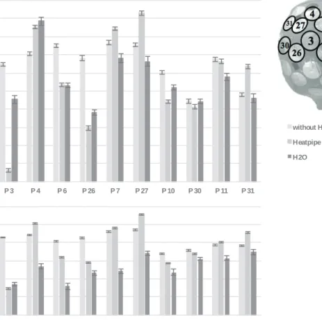
Fig. 5 shows the averaged temperatures and the corresponding standard deviations of the temperature sensors located on the top of the head for the reference measurement (without a HRS) and for the measurements of both of the HRSs under the conditions of T1=15°C, T2=28°C, RH=70 % and v=4.5 ms-1.
Fig. 5. Local results of evaluation of both heat relief systems (Heat pipe & Heat sink, H2O) compared to the measurement without a HRS concerning the temperature sensors on the top of the head (positions 3, 4, 6, 26, 7, 27, 10, 30, 11, 31); (a) T1=15°C, RH=70 % and v=4.5ms-1; (b) T2=28°C, RH=70% and v=4.5ms-1.
without HRS Heatpipe & Heat sink H2O a b 17 18 19 20 21 22 23 24 25 26 27 P 3 P 4 P 6 P 26 P 7 P 27 P 10 P 30 P 11 P 31 T empe rat ur e [ ° C] 28 29 30 31 32 33 34 P 3 P 4 P 6 P 26 P 7 P 27 P 10 P 30 P 11 P 31 Te m p er a tu re [ ° C]
By applying the HRS Heat pipe & Heat sink at sensor position 3 skin temperature decreases by 25 % at 15°C and by 9 % at 28°C in comparison to the values of the reference measurement. The surrounding area of sensor position 3 is not affected by this HRS. The detailed values can be seen in Fig. 5. The comparison of the local cooling effects of the HRS Heat pipe & Heat sink at 15°C and 28°C shows that skin temperatures are lower by up to 16 % at 15°C than at 28°C. By using the HRS H2O at especially sensor position 3 skin temperature decreases by 13 % at 15°C and by 8 % at 28°C in comparison to the values of the reference measurement. The skin temperature of the surrounding area of sensor position 3 is slightly reduced by the evaporation of the water. These decreases amount 3 % - 12 %. Concerning the cooling effect, the comparison of both of the HRSs shows up to 17 % (at position 3) better values at 15°C using the HRS Heat pipe & Heat sink. At 28°C no differences between the HRSs can be seen, in general. Particularly noticeable is the fact that temperatures measured at the positions 4, 7, 27 and 30 are up to 7 % higher than the values of the reference measurement.
4.Discussion
In addition to a detailed validation of the physical head model by e.g. FEM studies, it is necessary to check how exactly the physical thermal head model is reflecting the functions and the properties of a human head. However, it is very likely that due to different material properties in terms of heat transfer, the physical head model differs from the human head. This will be reviewed as part of a planned study with subjects. Additionally, the thermal head model is limited solely to the simulation of the core temperature. A sweating with a certain sweat rate cannot be simulated. As result, the cooling of the head, caused by the evaporation of sweat on the skin surface, cannot be taken into account.
The calculated energies deviate by a maximum of 1.9 % from the values of the reference measurement. This means that none of the HRSs can reduce temperature inside the head model. However, this is because of the reason that both concepts were initially evaluated only locally. Nonetheless, in both HRSs local cooling effects can be observed. Both of the HRSs were placed centrally located on top of sensor position 3. At this position the maximum influence were measured. The reason is that the copper disc is placed in direct contact to the thermal head model. In considering the application of the HRS Heat Pipe & Heat sink, it should be noted that the cooling affects a smaller area in contrast to HRS H2O. The reason is that the shape of the copper disc is not adjusted to the shape of the head. Thus, there is only one single point of contact to the head model. On the contrary, the HRS H2O adapts the shape of the head and therefore affects more temperature sensors or also a larger area. The comparison of both HRSs with respect to their local cooling effect shows a differing by up to 17 % at 15°C. The HRS Heat Pipe & Heat sink allows especially at sensor position 3 a better cooling. At 28°C the effect of both concepts is almost similar. Increased skin temperatures at positions 4, 7, 27, 10, 30, 11 and 31 compared to the values of the reference measurement can be justified by the fact that these temperature sensors are located in the slipstream of the HRS, respectively. Thus, heat dissipation by convection is very likely to be affected at these positions. Additionally, the effect in terms of cooling the head by vents cannot be ignored. Accordingly, a cooling system should not affect the effect of the vents. Instead, a combination of two cooling concepts would be conceivable. Thereby, vents should support HRSs. Regardless of the ambient temperature, the cooling effect by evaporation remains approximately the same in this study at both ambient temperatures. Due to a sufficiently large temperature gradient the HRS Heat Pipe & Heat sink has a better cooling effect than the HRS H2O. The reason is the improved external heat flow. However, the concepts must be in directly contact with the surface of the heat source in order to achieve the maximum impact.
Despite these results, both heat relief principles must be questioned critically. In certain situations the HRS H2O is likely inapplicable. It can be assumed that during activities with a relatively high sweat production no additional cooling of the head will happen by using this HRS. The cooling effect via evaporation is considerably affected by environmental conditions and by the activity. If the perspiration exceeds certain amounts that cannot completely evaporate, then no cooling effect due to the application of the HRS is to be expected. Concerning this, the maximum volume of water that can evaporate at the defined area of 78.5 cm2 was calculated in certain conditions (free convection). At the condition of 15°C and a heat flow of 64 W about 97.5 mgmin-1
can evaporate. At the condition of 28°C and Q=76 W about 116.9 mgmin-1 of water can evaporate. The amount of water used in this study is limited to approximately 0.12 mgmin-1 by technical reasons. Perhaps a better cooling effect would occur with a larger amount of water.
With regard to the evaluation of the HRS Heat Pipe & Heat sink it is important to note that in this case the impact by radiation was not considered. However, this could have a relatively large influence on the cooling effect of HRSs. Reversing the heat transfer an undesirable additional warming beneath the bicycle helmet may occur.
In general, an expansion of the cooling system on the entire helmet is definitely necessary. It requires heat pipes and a heat sink with other properties in order to transport the produced heat to the outside of the helmet. In addition to the used parts, there is a plurality of alternatively usable components. Heat pipes and heat sinks are available in various shapes and with different physical and thermal properties. The use of such components with different properties would be very likely to affect the heat transport and thus the cooling effect.
In this study the effect of the cooling systems is evaluated at just a single bicycle helmet. By applying the described cooling systems to other bicycle helmets the cooling effect may be different compared to the results presented in this study. The reason is the influence of number, size, arrangement and geometry of the vents in the helmet to the ventilation of the head.
It has to be noticed, that a technical implementation of the presented proof of concept and its optimization have to be adapted to international standards concerning comfort and safety of the user. This includes different aspects: weight, weight distribution and thus the dynamic behavior of the helmet with the cooling system.
5.Conclusion
Generally, it can be said that a bicycle helmet has sufficient space for integrating such a system in its structure. Concerning the cooling effect and the described disadvantages of the evaporative cooling principle, the HRS Heat Pipe & Heat sink is more suited for such an application in bicycle helmets. Nevertheless, it should be transferred to the entire head and its cooling effect should be evaluated accordingly. In the future, it is necessary to perform a detailed validation of both the thermal head model and the cooling systems. For this purpose FEM simulations can be used.
Another future goal is the expansion of the cooling concept to the entire helmet in consideration of the international standards. These standards include both safety and comfort of the user. Furthermore, the HRS has to be adapted to the shape of the bicycle helmet.
References
[1] Bauer, K.; Schick, S.; Wagner, A.; Zhou, K.; Peldschus, S.; Malczyk, A. (2015): Untersuchungen zur Schutzwirkung des Fahrradhelms. Hg.v. Unfallforschung der Versicherer. Gesamtverband der Deutschen Versicherungswirtschaft e. V. Berlin.
[2] Wandtner, B. (2015): Gurte, Kindersitze, Helme und Schutzkleidung - 2014. Hg.v. Bundesanstalt für Straßenwesen. Bergisch Gladbach.
[3] Finnoff, J. T.; Laskowski, E. R.; Altman, K. L.; Diehl, N. N. (2001): Barriers to Bicycle Helmet Use. In: PEDIATRICS 108 (1), S. e4-e4. DOI: 10.1542/peds.108.1.e4.
[4] Tomasits, J, Haber, P. (2011): Leistungsphysiologie. Grundlagen für Trainer, Physiotherapeuten und Masseure. 4., revised edition. Vienna: Springer-Verlag Vienna.
[5] Zwolińska, M.; Bogdan, A.; Fejdyś, M. Influence of different types of the internal system of the ballistic helmet shell on the thermal insulation measured by a manikin headform. In: International Journal of Industrial Ergonomics 2014; 44 (3), S. 421–427. DOI: 10.1016/j.ergon.2013.11.011.
[6] Alam, F.; Watkins, S.; Akbarzadeh, A.; Subic, A. (2006): A study of thermal comfort of a series of bicycle helmets. In: Proceedings of the 3rd BSME-ASME International Conference on Thermal Engineering, 20-22 December, 2006, Dhaka, Bangladesh.
[7] Annaheim, S.; Martines, N.; Rossi, R. (Hg.): 9-zone thermal head manikin to investigate local effects of bicycle helmets on heat transfer.
[8] Brühwiler, P. A. (2008): Radiant heat transfer of bicycle helmets and visors. In: J Sports Sci 26 (10), S. 1025–1031. DOI: 10.1080/02640410801930143. [9] Brühwiler, P. A. (2009): Role of the visor in forced convective heat loss with bicycle helmets. In: International Journal of Industrial Ergonomics 39 (1), S. 255–259. DOI: 10.1016/j.ergon.2008.08.001.
[10] Brühwiler, P. A.; Ducas, C.; Huber, R.; Bishop, P. A. (2004): Bicycle helmet ventilation and comfort angle dependence. In: Eur. J. Appl. Physiol. 92 (6), S. 698–701. DOI: 10.1007/s00421-004-1114-5.
[11] Bogerd, C. P.; Rossi, R. M.; Brühwiler, P. A. (2011): Thermal perception of ventilation changes in full-face motorcycle helmets: subject and manikin study. In: Ann Occup Hyg 55 (2), S. 192–201. DOI: 10.1093/annhyg/meq074.
[12] Bogerd, C. P.; Brühwiler, P. A. (2008): The role of head tilt, hair and wind speed on forced convective heat loss through full-face motorcycle helmets. A thermal manikin study. In: International Journal of Industrial Ergonomics 38 (3-4), S. 346–353. DOI: 10.1016/j.ergon.2008.01.003.
[13] Pang, T. Y.; Subic, A.; Takla, M. (2011): Thermal comfort of cricket helmets. An experimental study of heat distribution. In: Procedia Engineering 13, S. 252–257. DOI: 10.1016/j.proeng.2011.05.081.
[14] Pang, T. Y.; Subic, A.; Takla, M. (2013): A comparative experimental study of the thermal properties of cricket helmets. In: International Journal of Industrial Ergonomics 43 (2), S. 161–169. DOI: 10.1016/j.ergon.2012.12.003.
[15] Mustary, I.; Chowdhury, H.; Loganathan, B.; Alharthi, M.; Alam, F. (2014): Aerodynamic efficiency and thermal comfort of road racing bicycle helmets. In: 19th Asutralasian Fluid Mechanics Conference, 8-11 December, Melbourne, Australia.
[16] Bruyne, Guido de; Aerts, Jean-Marie; Vander Sloten, Jos; Goffin, Jan; Verpoest, Ignaas; Berckmans, Daniel (2012): Quantification of local ventilation efficiency under bicycle helmets. In: International Journal of Industrial Ergonomics 42 (3), S. 278–286. DOI: 10.1016/j.ergon.2012.02.003.
[17] Fiala, D. (1998): Dynamic Simulation of Human Heat Transfer and Thermal Comfort. Dissertation. De Monfort University; FH Stuttgart, Leicester & Stuttgart. Institut of Energy and Sustainable Development; Joseph-von-Eagle Institute für angewandte Forschung.