INTEGRATION OF A KNOWLEDGE BASED SYSTEM,
ANTIFICIAL NEURAL NETWORKS AND MULTIMEDIA
FOR GEAR DESIGN
D. Su, M. Wakelam and K Jambunathan
Department of Mechanical and Manufacturing Engineering
The Nottingham Trent University, Burton Street, Nottingham, NG1 4BU
Tel: +44 115 8482306, Fax: +44 115 9486506
E-mail:
[email protected];
Web site:
http://domme.ntu.ac.uk/mechdesABSTRACT
Design is a complicated area consisting of a combination of rules, technical information and personal judgement. The quality of design depends highly on the designer's knowledge and experience. This system attempts to simulate the design process and to capture design expertise by combining artificial neural networks (ANNs) and knowledge based system (KBS) together with multi-media (MM). It has been applied to the design of gears. Within the system the knowledge based system handles clearly defined design knowledge, the artificial neural networks capture knowledge which is difficult to quantify and multi-media provides a user-friendly interface prompting the user to input information and to retrieve results during design process. The finished system illustrates how features of different Artificial Intelligence techniques, KBS, ANNs and MM, are combined in a hybrid manner to conduct complicated design tasks.
Keywords Gears, mechanical design, artificial intelligence, design integration, engineering multimedia
1 INTRODUCTION
Gears are used in a great variety of applications, from large industrial drives to children’s toys. The design of gears is a complicated task, and has to take into account various aspects such as working conditions, materials, factors and forces acting upon the gears for their particular application. As gear technology has been in development over many years, the design process and methods are definable in most cases. Despite this, gear design is still a difficult task
and the quality of the design depends highly on the designer's knowledge and experience. The majority of the knowledge required to develop a successful design can be formed into an iterative process involving the manipulation of a series of rules, formulae, and technical information presented in design diagrams, with the outcome of one situation leading to a new set of rules, diagrams and formulae and a possible solution.
Computerisation of the design expertise can speed up the lengthy design process and enables the expertise to be available to non-expert users. An intelligent hybrid system has been developed which combines two artificial intelligence techniques, knowledge based systems (KBS) and artificial neural networks (ANNs), with multi-media techniques to provide a user-friendly interface. The system has been developed to be applicable for ill-defined design tasks, such as the technical information provided to the designer being incomplete which often occurs in the real design situations. In most cases, it is rare for all the factors which apply to a design are known, as such this system adopts an approach based around design information diagrams, formulae [1] and a set of design rules.
Within the system, the KBS is used to dealing with well defined design knowledge while the ANNs store knowledge based on empirical data or knowledge that would require the user to intercede and interpret. The KBS also structures the progress of the design, determining what steps to take next. Multi-media is used for two purposes, firstly to create a user-friendly interface with the system and secondly to coax a response from the user about knowledge that is not practical to be stored using a rule base or ANNs.
Knowledge based systems, or so called expert systems, have been applied in gear design, for example [9] and [10], which have greatly benefited the designers. However, as discussed in [8], they have several drawbacks, such as the inflexibility to adopt changes after system completion and the difficulties in handling ill-defined knowledge, which limit their application. These drawbacks have been successfully overcome in the new system presented here by the incorporation of the ANN approach. The application of ANNs in design in recent years has proved to be an attractive research area, and the combination of KBS and ANNs together with multi-media into gear design has enabled its strength and novelty.
2 SYSTEM OVERVIEW
2.1 System Structure
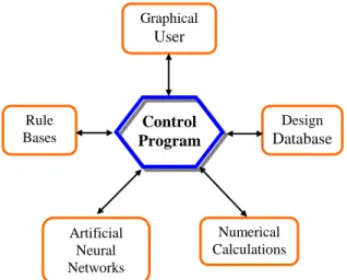
The system integrates KBS, ANNs, numerical analysis, user interfaces and databases into a single environment for the task of gear design. The progress of the design is co-ordinated and structured by a central control program which activates the appropriate set of production rules, ANN or Graphical User Interface dependant on the stage of the design. The system has been developed with a modular structure, consisting of several modules such as ANNs module, numerical calculation module, etc. The KBS consists of a central control program and production rule bases. The control program acts as a master and an interface between the different modules, co-ordinating the development of the design depending on the results obtained from previously activated modules and specifications defined by the user. The results from the modules and the users' specifications are stored and updated in the database as the design progresses. Figure 1 below shows how the modules interface with one another via the control program.
Figure 1 Schematic of Design System.
The system is developed with multiple techniques and represents a truly integrated approach. The control program is encoded in C++ and forms the centre of the system calling relevant modules when required. ANNs, numerical calculations and the rule base modules are also encoded in C++ and directly activated by the control program. The GUI is developed in Visual Basic, taking advantage of the graphical capabilities and user interface facilities. The
Graphical User Interface Control Program Rule Bases Design Database Artificial Neural Networks Numerical Calculations
database at present consists of ASCII files for storage, created by the conceptual design module [2] which proceeds this detailed design stage, and is updated and expanded as the design progresses with interrogation procedures embedded within the control program.
The design system follows an iterative process, refining a number of parameters, dimensions and features of the design until the design is correct.
2.2 System Description.
The system described in section 2.1 has been applied to computerise the detailed design process of involute gears, from the formulation of the design specification to the final dimensions and characteristics.
On activation of the system, design specifications, such as transmission power and gear ratio, are retrieved from the database and prompted from the user. From the initial values the system is able to determine a path the design will take. Missing parameters required for the design are obtained from either the information rule sets, ANNs or numerical calculation during the design process or directly from the user via the GUI.
At various points during the design process the user may be given the option of defining the design parameters, such as safety factors, or they may be obtained from the knowledge stored within the system in either the rule base or the ANNs. The added interaction with the user allows for ‘one off’ or special circumstances which are beyond the domain of the knowledge held by the system.
During the design process the control program enters into an iterative cycle to obtain values to produce an optimum design. For example, if the number of teeth on the designed gear is below the minimum practical, the system repeats the design process to re-define design parameters such as material, facewidth or pitch diameter values. The type of cycle, and inevitably the design, is governed by the path followed and the control rules which are fired. Firing an appropriate rule is determined within the control program based upon which control rules have been fired, results of
actions taken and positions within sequenced procedures. The control program fires rules and activates procedures until the design is complete.
The initial gear design generated is for the pinion gear. Once the pinion design is complete the dimensions and properties of the driven gear are directly obtainable based on the pinion's design, specification and relevant calculations. The final designs are stored in the data base for use by the gearbox design system and displayed for the user.
3. RULE ENCAPSCULATED KNOWLEDGE
As defined in [3], the knowledge is ‘ a collection of simple facts together with general rules representing some universe of discourse’. The KBS contains the design knowledge in the form of a series of production rules constructing a complex cognitive system. The production rules used within the system are a series of conditions and actions in the form of IF...THEN statements where the entire collection of rules forms the systems knowledge base. The system's knowledge base is the sum of the production rules which are allocated to the appropriate task.
The use of production rules and a control procedure presents a number of advantages for this application, as listed below:
the use of production rules does not require an external expert system shell therefore simplifying and speeding up the system.
the design process can be expressed in a structured fashion.
certainty values and firing methods do not require manipulating.
The production rules are in two forms: control rules and information rules. The control rules control the progress of the design (if a condition is met perform a task) and information rules contain specific data or information about a particular design configuration or property. The activation of the second type of rules is governed by the control rules.
The control rules hold the knowledge relating to the design's progress. These rules structure the design process and control its development, forming a ‘pseudo’ inference engine, activating the appropriate information rule depending on the circumstances applied and the stage of the design.
Example
IF facewidth ratio is not defined by user THEN activate facewidth information rules.
The control rules not only control the information rules, but also control the activation of other modules within the design systems.
Example
IF gear is through hardened THEN activate ANN module 1.
The information rules contain information in the form of numerical values, design features or simple equation which encapsulate the design information.
Examples
IF the gear is double helical and its heat treatment is nitrided and its mounting is symmetric THEN maximum facewidth ratio is 1.4.
The information rules contain specific information relating to an area in the design process and are grouped together in sub sets. This grouping aids in modification and maintenance of the knowledge stored in the rule base.
4 ARTIFICIAL NEURAL NETWORKS (ANNS)
ANNs within this system have been applied to the encapsulation of knowledge that is in a difficult or impractical form to store in a knowledge base or by mathematical expressions. ANNs have proved capable of storing data which appears disordered, such as for concept design data [2] and design retrieval [4] and in the use of mimicking complicated mathematical functions [5].
The information to be stored in the networks used within the design system is in such a form that the output is known for a given input. The information is in the form required by a supervised network thereby making this type of network a natural choice. The type of networks used by the system are multi-layer feedforward networks employing the back propagation technique whilst training. Training of a network is a time consuming process requiring adjustment of the structure (called topology), length of training (number of times the training set is presented to the network), learning and momentum coefficients. Studies have shown [6, 7] that there is no established method (at the moment) to determine the factors which affect the training process. Rules of thumb have been developed but are based on a particular application and are not generally transferable to other applications. The method of training is by trial and error.
In this application the networks are to simulate graphical information for gear design which is derived from experimental data. Each network’s purpose is to interpret the design diagrams and produce an output similar to manual results by reading off a graph and interpolating if necessary. Training and generation of the source code for the networks were performed using Professional II, a neural network package. The trial and error approach was used to modify the topologies and coefficients until the final networks were derived.
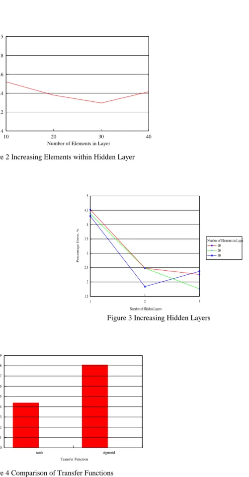
10 20 30 40 Number of Elements in Layer
4 4.2 4.4 4.6 4.8 5 Percentage Err or, %
Figure 2 Increasing Elements within Hidden Layer
1 2 3
Number of Hidden Layers 1.5 2 2.5 3 3.5 4 4.5 5 Pe rce ntage
Error, % Number of Elements in Layer
10 20 30
Figure 3 Increasing Hidden Layers
tanh sigmoid Transfer Function 0 1 2 3 4 5 6 7 8 9 Pe rce nta ge E rror, %
Analysis of the networks test results enabled certain guidelines to be established which may be applied to the training process. Figures 2 to 4 show observations made from training results.
increasing the number of elements in a hidden layer increases performance up to a point, after which performance did not significantly increase or actually decreases, see Figure 2.
increasing hidden layers and therefore connectivity of the network generally improves performance, see Figure 3.
Tanh transfer function was superior to using sigmoid.
Training was attempted using one of two different transfer functions, a hyperbolic tangent (tanh) and a sigmoid. In previous work [2] with ANNs the sigmoid function appeared the better suited. However in the current application it has been found, during training, that better performance may be achieved from the networks using the hyperbolic tangent transfer function, see figure 4.
During training the following observations were made:
after a point, increasing the training period did not improve the network's performance but instead caused it to degrade.
modifying the coefficients throughout the training period, starting with high values (i.e. 0.9 for learning coefficient) and finishing with very small (i.e. 0.001) improved network performance.
Training the networks for the system again demonstrated that networks suitable for one application may not be suitable for another.
5 MULTIMEDIA
Multimedia can be described as any combination of text, sound, graphics and video used to impart information to a user. When the user is able to interact with the information that is being conveyed the term then becomes interactive multi-media. The application of multi-media within this system is interactive. With the aid of Visual Basic a Graphical User Interface (GUI) has been created to provide a user-friendly interface for the extraction of information
about materials, heat treatment, applications and features of the design from the user. The GUI allows information to be presented in a clear and concise manner, allowing interaction between system and the user when decision making and defining specifications within a user-friendly environment. Relevant design options are presented to the user via the GUI depending on the stage the gear design is at, with additional information available upon request about any of the options.
Interaction with the design system through the GUI has three main purposes : prompts the user to provide essential information to complete the design.
provides a platform to store and reproduce technical information for the users quick and efficient use.
installs a sense of confidence in the system to control the design process as examples the given options may be applied to can be given. Also a sense of control over the design may be produced.
6. AN EXAMPLE
A design task has been conducted using the developed intelligent system with the following design specifications: Power transmitted: 15 kW
Input speed: 1450 rpm Speed reduction ratio: 10 : 1
Orientation of input to output: parallel Life of transmission: 1000000 hrs
6.1 Conceptual Design
Using the knowledge stored in the knowledge base, the system works out that the suitable concept for the design is a two-stage system with parallel input/output shaft orientation. Then the ANNs are used to select suitable components
for each stage. The input to the network is a list of specifications as shown below, of which '1' indicates the item is selected while '0' is not:
1 Ratio Accuracy
1 Transmission Smoothness
1 Transmission Efficiency
0 Ease of Maintenance and Assembly
0 ease of Manufacture 0 Cost 1 Weight 0 Load Distribution 0 Manufacturing Accuracy 1 Size
Output pattern from Component Network is as follows
0.977055 Double Helical
0.999910 Single Helical
0.936947 Spur
0.747440 Belt Drive
0.591291 Chain
The most suitable component selected by the network is the single helical gear which has the highest output value. The rules governing the component hierarchy use this information to select the appropriate network for the next transmission stage. As the component was a single helical gear, the double helical gear cannot be used in the design, therefore, the network that excludes this component is used for the second stage. The input pattern is presented to the network, and similarly, the helical gear pair is selected by the ANNs for the second stage.
6.2 Detail Design
At detail design stage, the system interfaces with numerical analysis programs for gear strength calculation, sets of ANNs for technical information retrieval and data processing programs to conduct the design.
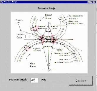
During the process, the user-friendly interfaces developed using multimedia technique are used to guide the user to perform the tasks, examples of which are shown in Figures 5 and 6.
The detail design process is shown in Figure 7. As can be seen, both the KBS and ANNs are involved in the design. The overall process is controlled by the KBS using production rules. The ANNs are used in two places:
As shown in Step 2, the ANNs are employed to obtain design factors. Those factors include safety factors, pitch accuracy, lead accuracy and face load factors. An example of selecting such a factor with the aid of ANNs is given in [8].
As shown in Step 5, the ANNs are used for design retrieval to select gear structure. For further detail, see [11]. The ANNs are back propagation feed forward networks.
The final results obtained are shown in table 1.
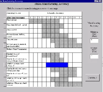
Figure 6 The GUI for selection of hardness and manufacturing process
Figure 7. Gear design process Step 5 Step 4 Step 3 Step 7 Step 6 Step 2 Step1 Yes No Gear design finish Gear design specification (PDS)
Obtain design factors (ANNs) Initial design Design retrieval for selection of gear structure (ANNs) Conflict with other components in the system? Modify PDS Design optimisation program
Table 1. The final results
Type Pinion1 Gear1 Pinion2 Gear2
Number of Teeth 26 97 31 83 Module (mm) 3.0 3.0 4.5 4.5 Facewidth (mm) 72.0 72.0 104.0 104.0 Pressure Angle (deg.) 17.5 17.5 17.5 17.5 Helix Angle (deg.) 35.0 35.0 35.0 35.0 Tip Diameter (mm) 104.2 365.4 183.3 469.0 Tooth Depth (mm) 11.9 11.9 19.5 19.5 Bore Diameter
(mm)
76.0 91.0 91.0 181.0 Rack Tip Radius
(mm) 0.900 0.900 1.125 1.125 Addendum Coefficient 1.50 1.50 1.65 1.65 Addendum Modification Coefficient -0.004 0.200 -0.201 -0.201 Permissible Contact Stress (N/mm) 344.4 371.9 334.1 352.1 Actual Contact Stress (N/mm) 343.3 343.3 317.4 317.4 Permissible Bending Stress (N/mm) 490.5 498.0 489.3 492.7 Actual Bending Stress (N/mm) 48.7 48.6 55.5 55.5 Contact Ratio 6.32 6.32 6.19 6.19 Transverse Contact Ratio 1.94 1.94 1.97 1.97 Centre distance: Total 360.2 mm
between shafts 1st Stage 151.6 mm 2nd Stage 208.6 mm
7. DISCUSSION AND CONCLUSIONS
An intelligent hybrid system has been successfully developed for gear design, by means of combining the Artificial Intelligence techniques of KBS and ANNs with numerical calculations, GUIs and data handling.
The method of forming the knowledge base as a series of sub-sets of production rules has proven effective and successful. The qualities of trace-ability and self-structured firing are not required by the system and would only increase complexity of the system by introduction of an expert shell. Formation of the rules into sub-sets allows updating and modification of the rules to be performed conveniently.
The use of ANNs to capture the data held within a design diagram has proven to be an effective tool. The information may have been encoded using a package such as MATLAB by manipulation of the equations, however, it would increases the complexity of the system unnecessarily. Modularising the ANNs within the system also allows replacement of new or modified ANNs to be quick and simple. The main drawback of using ANNs in the system is the difficulties encountered during their training. Several factors affect a network’s training. The observations made during the training of the networks used within the system may be applied to networks of similar form.
This system has been applied to the design of gears, however, the methodologies developed can also be applied in other areas. The methodologies include definition of the problem, generation of knowledge bases based on both circumstances and actions, simulation of quantifiable data, training ANNs with ambiguous or unsuitable modelling information, and interface with the user through a user-friendly medium.
Based on the work described in this paper, a more powerful system for power transmission system design is being developed by the Mechanical Design and Concurrent Engineering Research Group at The Nottingham Trent University. It blends KBS, ANNs, genetic algorithms and CAD/CAM/CAE into a single environment and covers the total design process including conceptual design, detail design and manufacture. Current progress has been reported in [11].
REFERENCES
[1]. ISO/TC-60, 1994, ISO6336--Calculation of load capacity of spur and helical gears, International Organisation for Standardization, Geneva.
[2]. D. Su, K.Henthorn, K. Jambunathan and M. Wakelam, 1996, A Rule Based and Artificial Neural Network System for Conceptual Design, International Journal of INGENIUM 96 (1), pp. 1-9.
[3]. R. A. Frost, 1986 Introduction to Knowledge Base Systems, Collins Professional and Technical Books, London, p. 3
[4]. T. P. Caudell, S. D. G. Smith, R. Escobedo and M. Anderson, 1994, NIRS: Large Scale ART-1 Neural Architectures for Engineering Design Retrieval, Neural Networks, Vol. 7, No. 9, Elsevier Science Ltd., pp. 1339-1350
[5]. Y. F. Lou and P. Brunn, 1995, Using Artificial Neural Networks for Solving Engineering Problems, Proceedings, the Thirty-first Intentional MATADOR Conference, Macmillan Press Ltd., pp. 635-640
[6]. K. K. Tay ,1996, Investigation into Factors Affecting Training of an Artificial Neural Network for Conceptual Design, Final Year B.Eng. Thesis, Department of Mechanical Engineering, The Nottingham Trent University, England.
[7]. H. Rowlands, 1996, A hybrid Approach for the Optimum Design Using a Genetic Algorithm, A Neural Network and The Taguchi Method., Proceedings of ACEDC’96, University of Plymouth, pp 205-211
[8]. D Su, 1998, Application of expert system and artificial neural networks for design knowledge retrieval, proceedings, Engineering Design Conference '98, an International Conference at Brunel University, UK, 23-25 June 1998, pp 371 - 378.
[9]. D Su, 1994, Gearbox KBIS: a Prototype Knowledge-Based Integrated System for Gearbox Design, proceedings, 1994 International Gear Conference, 7-9, September, Newcastle upon Tyne, U.K. pp 201-205.
[10]. Yiu-Wing Chan and Siang-Kok Sim, 1998, An expert system for gearing design application, International Journal of Computer Applications in Technology, Vol. 11, Nos 1/2, pp. 11-16
[11]. D Su, 1999, Design automation with the aids of multiple artificial intelligence techniques, Concurrent Engineering: Research and Application journal, Vol 7, No 1, March 1999, Technomic Publishing, pp 23-30.
BIOGRAPHY
Dr Daizhong Su is a Reader in the Mechanical and Manufacturing Engineering Department of The Nottingham
Trent University, UK. He chairs the Engineering Design and CAE subject group and leads the Concurrent Engineering Research Laboratory. His research interests include engineering design, artificial intelligence, evolutionary optimisation, multimedia, CAD/CAM/CAE and concurrent engineering with about 100 refereed publications.
Dr Mark Wakelam was a researcher in the Mechanical and Manufacturing Engineering Department of The
Nottingham Trent University and received his PhD degree from the University in 1998. His Ph.D research was in the area of combining artificial neural networks, genetic algorithms and production rules into a hybrid intelligent system to integrate the various stages of the design process into a single environment. He currently works in the 3D Scanners Ltd, UK
Professor Nath Jambunathan graduated form the University of Wales in Mechanical Engineering. After several
years of research both in industry and academia, he was awarded a Ph.D. in 1983 for his work on heat transfer through extended surfaces. He leads the Heat Transfer and Fluid Flow Research Group and is the Research Co-ordinator in the Mechanical and Manufacturing Engineering Department of The Nottingham Trent University . He is particularly interested in computer modelling and experimental techniques associated with heat transfer and fluid flow, and has experience in the development of Knowledge Based Front End for CFD. His recent interest has been in the application of AI to Jet Impingement and Flow Visualisation.