ALMA MATER STUDIORUM
UNIVERSIT `
A DEGLI STUDI DI BOLOGNA
Dottorato di Ricerca in Ingegneria Elettronica,
Telecomunicazioni e Tecnologie dell’Informazione
Dipartimento di Ingegneria dell’Energia Elettrica e
dell’Informazione “Guglielmo Marconi”
Ciclo XXIX
Settore concorsuale:09/F2 - TELECOMUNICAZIONI
Settore scientifico disciplinare:ING-INF/03 - TELECOMUNICAZIONI
VIRTUALIZED NETWORK
INFRASTRUCTURES:
PERFORMANCE ANALYSIS,
DESIGN AND IMPLEMENTATION
Presentata da
:
CHIARA CONTOLI
Coordinatore Dottorato
:
Chiar.mo Prof. Ing.
ALESSANDRO
VANELLI-CORALLI
Relatore
:
Chiar.mo Prof. Ing.
FRANCO CALLEGATI
Correlatore
:
Chiar.mo Prof. Ing.
WALTER CERRONI
INDEX TERMS
Software Defined Networking
Network Function Virtualization
Service Function Chaining
OpenStack Performance
Intent Driven Networking
Contents
Summary vii
1 Introduction 1
1.1 Internet Ossification . . . 1
1.2 A modern approach to networking . . . 2
1.2.1 Software Defined Networking . . . 2
1.2.2 Network Function Virtualization . . . 5
1.3 Motivation . . . 7
1.4 Thesis Contributions . . . 8
2 Performance of Network Virtualization in Cloud Infrastructures 11 2.1 Main concepts of cloud Network Virtualization . . . 13
2.2 OpenStack Virtual Network Infrastructure . . . 15
2.3 Experimental Testbed . . . 20
2.3.1 Single-tenant cloud computing scenario . . . 21
2.3.2 Multi-tenant NFV scenario with dedicated network functions . . . 22
2.3.3 Multi-tenant NFV scenario with shared network functions . . . 25
2.4 OpenStack performance: numerical results . . . 27
2.4.1 Benchmark performance . . . 27
2.4.2 Single-tenant cloud computing scenario . . . 28
2.4.3 Multi-tenant NFV scenario with dedicated network functions . . . 30
2.4.4 Multi-tenant NFV scenario with shared network functions . . . 33
3 SDN Control plane
design for Dynamic NFV 39
3.1 Dynamic chaining of Virtual
Network Functions in edge-networks . . . 40
3.1.1 Reference network scenario . . . 41
3.1.2 Case studies: Layer 2 and Layer 3 topologies . . . 42
3.1.3 Design logic for Layer 2 & Layer 3 topology . . . 45
3.1.4 Proof of concept . . . 49
3.2 Coordinating dynamic SDN control . . . 52
3.2.1 The Finite State Machine approach . . . 52
3.2.2 Applying stateful SDN control to a Layer-2 NFV Topology . . . 56
3.2.3 Preliminary experimental results . . . 59
3.2.4 How can Telco industry and Service Providers benefit from stateful approach? . . . 63
3.2.5 A SDN use case for Service Provider Networks . . . 64
3.2.6 Moving implementation to production-level environment: the Ericsson Cloud Lab . . . 67
3.2.7 Proof of concept: VNF chaining for QoS enforcement & dynamic traffic steering . . . 69
3.2.8 Experimental results on Ericsson Cloud Lab environment . . . 74
3.3 Conclusion . . . 77
4 Towards Network Management and Orchestration 79 4.1 An Intent-based Approach to Virtualized Infrastructure Management . . . 81
4.2 Reference NFV architecture . . . 81
4.3 Intent-based NBI for dynamic Service Function Chaining . . . 84
4.4 Implementation of the VIM on the ONOS platform . . . 87
4.5 Validation of the PoC . . . 90
4.6 Experimental results . . . 91 4.7 Conclusion . . . 93 5 Conclusions 95 5.1 Summary of Contributions . . . 95 5.2 Future Work . . . 98 Acknowledgments 113
Summary
In recent decades, there has been a tremendous evolution in the traffic on the Internet and enterprises networks. Networks assisted since the beginning to two phenomena: on the one hand, the birth of a multitude of applica-tions, each posing different requirements; on the other hand, the explosion of personal mobile networking, with an ever increasing demand of devices that require connectivity. These trends resulted in increased network com-plexity, leading to difficult management and high costs. At the same time, evolution in the Information Technology (IT) field led to the birth of cloud computing and growth of virtualization technologies, opening new opportu-nities not only for companies but for individuals (be it PC or mobile users), as well as Service and Infrastructure Providers. Emerging technologies such as Software Defined Networking (SDN) and Network Functions Virtualiza-tion (NFV) seems to be promising soluVirtualiza-tions to today’s network problems. Neither standardized solutions, nor how to properly combine their usage to achieve flexible and proactive control management have been discovered yet. This Ph.D. thesis focuses on the exploration of three plane of functional-ity in which software-defined (computer) networks can be divided: the data, the control and the management plane. SDN aims at introducing network programmability by separating the control from the data plane, besides sim-plifying network management and the development and deployment of new networking features. Whereas NFV aims at introducing network flexibility by implementing network functionality in software, leveraging IT virtualiza-tion techniques, so that can now run on general-purpose hardware. Such flexibility allows for an efficient provision of the network functionality, that can be instantiated, moved or disposed in an on-demand fashion, thus also leading to the benefit of reduced costs and reduced power consumption.
The work presented here is the outcome of part of the research activities carried out by the Network research group at the Department of Electri-cal, Electronics and Information Engineering “G. Marconi” (DEI), NetLAB (Network Laboratory) at the University of Bologna, Italy. In particular, the activities performed by the Network Research Group have been partially
funded by EIT ICT Labs (now EIT Digital): Activity 2013 “Smart Network at the Edge”, task T1303A - Enable Efficient and Seamless Network-Cloud Integration, Activity 2015 “SDN at the Edges” - Action Line on Future Networking Solutions and, in this latter action line, Activity “CC4BA - Cer-tification Centre for Business Acceleration of SDN and NFV”.
In this thesis we present insights on several aspects of network virtualiza-tion, starting from virtual network performance of cloud computing infras-tructures, and introducing the Service Function Chaining (SFC) mechanism, discussing its analysis, design and implementation. In particular, the original contribution of this dissertation concerns (i) performance evaluation of the OpenStack cloud platform (the data plane); (ii) the design and implementa-tion of a stateful SDN controller for dynamic SFC (the control plane); (iii) design, implementation and performance analysis of a proposed Intent-based approach for dynamic SFC (the management plane).
Chapter 1
Introduction
1.1
Internet Ossification
Internet and enterprises networks in past decades have experienced two dif-ferent trends: i) an ever increasing birth of difdif-ferent applications; ii) an ever increasing demand of connectivity by devices, be it mobile or personal. Applications range from e-mail exchange, file transfer, browsing hyper-text contents (the very early Internet applications), to buying on-line, videocon-ferencing, online video gaming, watching movies, downloading music and others multimedia contents, etc., which are now the dominant applications that have caused a significant evolution in the traffic of both Internet and enterprises networks. Such applications pose different requirements to the network in terms of delay, jitter and loss tolerance besides throughput de-mand; these are also known as Quality of Service (QoS) parameters. For example, e-mail can tolerate high value of delay, jitter and loss, and demands low throughput, while applications such as videoconferencing and Voice over IP (VoIP) can tolerate low value of delay, jitter and loss and demand medi-um/high and low value of throughput, respectively. Keeping an acceptable level of performance is not the only challenge a network has to deal with; other challenges, for example, are security, host mobility, (dynamic) assign-ment of (private) addresses that all together made the network evolve in such a way that deploying a new service in todays networks is difficult.
To cope with such challenges, networks have been enhanced with several functions, such as Intrusion Detection Systems (IDS), Deep Packet Inspector (DPI), Firewalls, Network Address Translator (NAT), packet filtering, Wide Area Network Accelerator (WANA), load balancer, traffic shaper, just to name a few. Such functions are usually implemented on closed, proprietary and expensive hardware by a plurality of vendors, and are also known as
middle-boxes. As surveyed by Sherry et al. in 2012 [1], on a study of 57 enterprise networks, the number of middle-boxes deployed is comparable to the number of routers in a network. Moreover, large networks in window time of 5 years have spent over a million of dollars on middle-boxes, while small to medium networks have spent between $5,000-$50,000. Last, but not least, the multiplicity of vendors equipment requires high-skilled teams with the necessary expertise to be capable of managing all the heterogeneous devices composing the network. An additional obstacle comes from the fact that updates for such devices comes with hardware upgrade, thus leading to the so called vendor lock-in effect. This effect, so far, resulted in deploying new hardware to get new features, making todays networks expensive and difficult to manage.
1.2
A modern approach to networking
Promising solutions seem to come from emerging paradigms such as Soft-ware Defined Networking (SDN), Network Function Virtualization (NFV) and advances made in the Information Technologies (IT) field.
1.2.1
Software Defined Networking
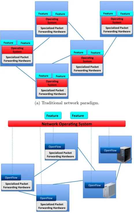
A comparison between traditional and SDN approach is given in Fig. 1.11.
Historically, control plane and data plane have always been co-located, to-gether with provided features, on the same specialized hardware as shown in Fig. 1.1a. With such approach, proper control routing protocols (e.g., Open Shortest Path First, Boarder Gateway Protocol) run in a distributed fashion to discover, compute adjacency and learn the complete network topology. In-stead, the SDN paradigm refers to an architecture that decouple the control plane from the data plane, thus moving the intelligence of the network to a (logically) centralized entity known as controller, as can be seen in Fig. 1.1b. With this approach, devices are just devoted to simply forwarding packets, while the control logic is moved to a Network Operating System (NOS) and applications running on top of it. To achieve this separation, two interfaces are provided: i) the North Bound Interface (NBI), ii) the South Bound In-terface (SBI).
The NBI is located between the NOS and the applications and its goal is twofold: on the one hand, it provides an API (Application Programming In-terface) to applications developers; on the other one, it provides abstractions to hide lower level details (e.g., how the forwarding devices are programmed).
Specialized Packet Forwarding Hardware Opera6ng System Feature Feature Specialized Packet Forwarding Hardware Opera6ng System Feature Feature Specialized Packet Forwarding Hardware Opera6ng System Feature Feature Specialized Packet Forwarding Hardware Opera6ng System Feature Feature Specialized Packet Forwarding Hardware Opera6ng System Feature Feature
(a) Traditional network paradigm.
Specialized Packet Forwarding Hardware
Network Opera7ng System
Feature Feature OpenFlow Specialized Packet Forwarding Hardware OpenFlow Specialized Packet Forwarding Hardware OpenFlow OpenFlow OpenFlow (b) SDN network paradigm.
The SBI is instead located between the NOS and the infrastructure composed of forwarding devices, with a twofold goal analogous to the one offered by the NBI: on the one hand, it provides an open interface that allow to program forwarding tables; on the other one, since southbound protocol can be seen as plug-in between the NOS and the infrastructure, it makes the NOS protocol agnostic.
The most adopted southbound interface is OpenFlow [2], which provides a protocol for the interaction between the NOS and underlying (OpenFlow enabled) devices (as can also be seen in Fig. 1.1b). OpenFlow provides an abstraction of a pipeline of flow tables; flow tables are composed of entries characterized by:
• a matching rule;
• actions to be executed on matching packets; • counters to keep track of flows/packets statistics.
Identifying SDN with OpenFlow would not be correct, especially because SDN is not a new concept. As well surveyed by Kreutz et al. in [3], SDN has a long history that comes from programmable networks, such as active net-works, programmable ATM networks and prior attempt to separate control and data plane, such as NCP (Network Control Platform) and RCP (Routing Control Platform), which find roots in the 80s and 90s. Besides OpenFlow, other more recent approaches for data plane programmability comes from ForCES (Forwarding and Control Element Separation) and POF (Protocol Oblivious Forwarding). In such SDN survey, authors also clarify the fact that also the concept of NOS is not new; in fact, traditional network devices are equipped with proprietary operating systems (e.g., Cisco IOS, JunOS, to name a few) that allow to manage and configure devices using device-specific commands. The problem is that network designers have to deal with the lack of abstractions for device details, and deal with complicated distributed algo-rithms. Instead, in SDN approach the NOS is usually implemented by control platforms (e.g., NOX, ONOS, OpenDaylight, OpenContrail, to name a few) in a software fashion that runs on commodity hardware. Control platforms differs in architecture and design elements, besides in services, components and interfaces (and the way those are) provided.
Therefore, main advantages introduced by the SDN approach can be sum-marized as follow:
• simplifying network management;
• reducing complexity when it comes to give birth to new protocols and network applications.
To recap, such advantages are brought both by the abstractions provided by NOS to network developers and external applications willing to interact with the control platform, and by the open programmable interface that provides an abstraction for the forwarding mechanism, which is vendor in-dependent and so do not require to know vendor-specific implementations, thus also leading to increased network programmability.
1.2.2
Network Function Virtualization
A complementary technology to SDN is NFV, and a comparison with tradi-tional approach is given in Fig. 1.2. As can be seen in Fig. 1.2a, traditradi-tional ap-proach consider proprietary hardware devices (middle-boxes) deployed along the path between source and destination. Operators typically apply an or-dered set of network functions, i.e. a service chain, to a given traffic class or to a given user (or class of users). In the case of functions implemented by middle-boxes this requires vendor-specific configuration and management tasks, i.e., reconfiguring switches, routers, network connectivity, etc. The increased complexity and costs due to high capitol investments and network management encouraged telecommunication network operators, infrastruc-ture providers (IPs) and enterprises to seek for alternative approaches. With the complicity of advances in virtualization technologies made in the IT fields, and the high capacity of standard server, NFV came to birth. As shown in Fig. 1.2b, network functions are now virtualized in software that can run on standard server hardware. So, NFV decouples the network functionality from underlying proprietary hardware, opening new opportunities for companies, Service and Infrastructure Providers.
As the European Telecommunications Standard Institute (ETSI) says in its first white paper [4], NFV takes advantage of two enabling technologies:
• cloud computing;
• industry standard high volume servers.
In particular, the cloud computing provides matured hardware virtualization mechanisms through hypervisors, as well as software Ethernet switches that allow traffic to flow between Virtual Machines (VMs) and physical interfaces. The adoption of such mechanism for Network Functions (NFs) leverage the cloud computing paradigm, that is, the service on-demand model; with this model, NFs could be instantiated, removed or migrated to any location in the
(a) Traditional network devices deployment: hardware middle-boxes.
(b) NFV network devices deployment: commodity hardware.
Figure 1.2: The NFV innovation.
network, without the need of deploying new hardware. Such model is also fostered by cloud computing infrastructure, that allow to virtualize compute, storage as well as network resources thus creating an unprecedented degree of flexibility. Moreover, cloud computing infrastructure should be capable of providing orchestration and management mechanisms that allow to automate VMs instantiation and deal with, for example, VMs allocation and recovery due to failure.
High volume servers adoption allow to take advantage of the economies of scale and of general purpose hardware that could replace middle-boxes to implement virtual network appliances. In fact, if we look again at Fig. 1.1b, according to the SDN vision the underlying infrastructure can be composed both of traditional proprietary solution running on specialized hardware and commodity white box solution2.
Therefore, main advantages introduced by NFV approach can be sum-marized as follow:
• increasing flexibility and efficient provisioning of network functions;
• reducing equipment costs and power consuption;
• reducing time-to-market by allowing software and hardware to evolve independently;
• supporting hardware resource sharing among multiple (concurrent) soft-ware instances, providing proper isolation mechanisms.
1.3
Motivation
SDN and NFV are independent of each other; NFV can be implemented without SDN being in place and vice-versa, but can leverage mutual ben-efits. Combining their usage can bring advantages to the telecommunica-tions industry in terms of Operational Costs (Opex) and Capital Expendi-ture (Capex) reduction; nevertheless, this evolution does not come without challenges. In this thesis, we focus in particular on performance trade-off and management concerns, considering scenario of future telecommunication network infrastructures that are of interest for network operators, service and infrastructure providers.
Such evolution will likely take place at network edges, where most of network functionalities are located. The vision is that future edge networks will take the shape of a data centers (interconnected by a stateless optical core network) where NFs will be provisioned. Several service providers (e.g., AT&T, SK Telecom to cite a few) are leading both research and development in this direction, aiming at providing to their customers solutions that take full advantage of combination among SDN, NFV and elasticity of commodity clouds so that they are able to bring data centers economies and cloud agility to Telco Central Office3.
If this will be the case, in spite of improved standard hardware performance, it is worth investigating if virtualized networks will provide performance com-parable to those achieved with current physical networks. Therefore, perfor-mance of underlying platform should be known in order to achieve a bet-ter planning about how properly dimension networks and virtual appliances placement.
Both industry and academia are encouraged to contribute to help the process of convergence between IT and network standardization. Therefore, several effort is put in the definition of reference SDN-NFV architectures that combines several functional blocks that need to be properly managed and orchestrated. For example, Verizon service provider published the first
version of its SDN-NFV architecture as a network infrastructure planning in February 2016 [5]. From an operational efficiency point of view, dynamic traffic steering and Service Function Chaining (SFC) are one of the main goals of SDN-NFV architectures.
Without doubt, dynamic traffic steering and SFC are correlated; SFC is about chaining NFs that can be deployed on the same physical node or across multiple ones; in fact, being capable of dynamically steering traffic towards required NFs is a key factor. Therefore, combining SDN and NFV aspects requires investigation from i) control plane and ii) management & orchestra-tion perspective. Orchestraorchestra-tion can be seen as a subset of the management in the context of combining NFV and SDN.
Control plane investigation is needed to understand how control plane can achieve proper traffic steering taking into account the fact that it has to deal with a multiplicity of users, and the fact that service chain can change over time. Management & orchestration, considering as a reference architecture the one proposed by ETSI [6], is a broad topic, but one of the most critical interface is the one between the cloud orchestration systems and SDN con-trollers4. The orchestrator component in the ETSI architecture is defined as
a functional block that has several responsibilities. According to the Open Networking Foundation (ONF), such critical interface could benefit of the so called Intent-based approach; recently, ONF published a technical report in which definitions and principles of Intent NBI approach is given [7] but how to implement such interface is left open.
1.4
Thesis Contributions
How to properly combine SDN and NFV usage to achieve flexible and proac-tive control management, nor standardized solutions have been discovered yet. In order to help answer to this question and to help addresses perfor-mance, and management & orchestration concerns described in the previous section, we performed a study that cross all the three planes of functionality a SDN-NFV network can be divided in: i) data plane; ii) control plane; iii) management plane. In this thesis we make the following contributions:
• Performance Analysis: such contribution is given at all planes, and
can be summarized as follow:
- data plane: in order to explore performance concerns of underlying platform, we lead a deep investigation of performance evaluation
4
of one of the most widely adopted cloud platform: OpenStack. We focus in particular on performance of its virtual network in-frastructure, as well as on performance of simple NFV use cases scenario deployment (Chapter 2).
- control plane: we investigate the performance of a stateful ap-proach to dynamic traffic steering aimed at achieving fully dy-namic SFC; such evaluation is led both on an OpenStack deploy-ment at the University of Bologna, and on a real production en-vironment (Chapter 3).
- management: we investigate the performance of our proposed In-tent NBI approach aimed at providing a vendor-independent, tech-nology agnostic technique for controlling dynamic SFC on top of a SDN infrastructure (Chapter 3).
• Design:
- control plane: we propose the design of a stateful SDN control plane as a general approach to service chain reconfiguration; in particular, we leverage the abstraction provided by a Mealy ma-chine, that allow us to model the controller behavior to achieve fully dynamic and adaptive SFC (Chapter 3).
- management: we propose the design of vendor-independent, tech-nology agnostic Intent-based NBI approach that could be put in place between an orchestrator and a SDN controller platform; our approach allow to dynamically handle a SFC on top of SDN in-frastructure (Chapter 4).
• Implementation:
- control plane: we implemented the stateful finite state machine on the Ryu framework; in order to prove the feasibility of our ap-proach, we developed a proof-of-concept (PoC) both on an Open-Stack deployment at the University of Bologna and on a real like production environment (Chapter 3).
- management: to show the feasibility of our approach, we imple-mented such Intent NBI as an application running on top of the ONOS control platform; whereas the first validation of our PoC is performed on top of an OpenFlow network infrastructure emu-lated with Mininet (Chapter 4).
Chapter 2
Performance of Network
Virtualization
in Cloud Infrastructures
Despite the original vision of the Internet as a set of networks interconnected by distributed layer 3 routing nodes, nowadays IP datagrams are not simply forwarded to their final destination based on IP header and next-hop infor-mation. A number of so called middle-boxes process IP traffic performing cross layer tasks such as address translation, packet inspection and filtering, QoS management, and load balancing. They represent a significant frac-tion of network operators’ capital and operafrac-tional expenses. Moreover, they are closed systems, and the deployment of new communication services is strongly dependent on the product capabilities, causing the so-called “ven-dor lock-in” and Internet “ossification” phenomena [8]. A possible solution to this problem is the adoption of virtualized middle-boxes based on open software and hardware solutions. Network virtualization brings great advan-tages in terms of flexible network management, performed at the software level, and possible coexistence of multiple customers sharing the same phys-ical infrastructure (i.e., multitenancy). Network virtualization solutions are already widely deployed at different protocol layers, including Virtual Local Area Networks (VLANs), multilayer Virtual Private Network (VPN) tunnels over public wide-area interconnections, and Overlay Networks [9].
Today the combination of emerging technologies such as Network Func-tion VirtualizaFunc-tion (NFV) andSoftware Defined Networking (SDN) promises to bring innovation one step further. SDN provides a more flexible and pro-grammatic control of network devices and fosters new forms of virtualization that will definitely change the shape of future network architectures [10], while NFV defines standards to deploy software-based building blocks
im-plementing highly flexible network service chains capable of adapting to the rapidly changing user requirements [11].
As a consequence, it is possible to imagine a medium-term evolution of the network architectures where middle- boxes will turn into virtual machines (VMs) implementing network functions within cloud computing infrastruc-tures, and telco central offices will be replaced by data centers located at the edge of the network [12, 13, 14]. Network operators will take advantage of the increased flexibility and reduced deployment costs typical of the cloud-based approach, paving the way to the upcoming software-centric evolution of telecommunications [15]. However, a number of challenges must be dealt with, in terms of system integration, data center management, and packet processing performance. For instance, if VLANs are used in the physical switches and in the virtual LANs within the cloud infrastructure, a suitable integration is necessary, and the coexistence of different IP virtual networks dedicated to multiple tenants must be seamlessly guaranteed with proper isolation.
Then a few questions are naturally raised: Will cloud computing plat-forms be actually capable of satisfying the requirements of complex commu-nication environments such as the operators edge networks? Will data centers be able to effectively replace the existing telco infrastructures at the edge? Will virtualized networks provide performance comparable to those achieved with current physical networks, or will they pose significant limitations? In-deed the answer to this question will be a function of the cloud management platform considered. In this work the focus is on OpenStack, which is among the state-of-the-art Linux-based virtualization and cloud management tools. Developed by the open-source software community, OpenStack implements the Infrastructure-as-a-Service (IaaS) paradigm in a multitenant context [16]. To the best of our knowledge, not much work has been reported about the actual performance limits of network virtualization in OpenStack cloud infrastructures under the NFV scenario. Some authors assessed the perfor-mance of Linux-based virtual switching [17, 18], while others investigated network performance in public cloud services [19]. Solutions for low-latency SDN implementation on high-performance cloud platforms have also been developed [20]. However, none of the above works specifically deals with NFV scenarios on OpenStack platform. Although some mechanisms for ef-fectively placing virtual network functions within an OpenStack cloud have been presented [21], a detailed analysis of their network performance has not been provided yet.
This chapter aims at providing insights on how the OpenStack platform implements multitenant network virtualization, focusing in particular on the performance issues, trying to fill a gap that is starting to get the attention
also from the OpenStack developer community [22]. The objective is to identify performance bottlenecks in the cloud implementation of the NFV paradigms. An ad hoc set of experiments were designed to evaluate the OpenStack performance under critical load conditions, in both single tenant and multitenant scenarios. The results reported in this work extend the preliminary assessment published in [23, 24].
In the following, we briefly introduce in section 2.1 the main concepts of network virtualization, discussing examples of virtualization techniques; we dive into the OpenStack virtual network architecture explanation (section 2.2), focusing our attention on the main components of the infrastructure and its network elements; then we present the experimental test-bed setup that we have deployed to assess OpenStack performance, investigating several use case scenarios (section 2.3). Finally, we discuss the numerical results and draw some conclusions (sections 2.4 and 3.3, respectively).
2.1
Main concepts of cloud
Network Virtualization
Generally speaking network virtualization is not a new concept. Virtual LANs, Virtual Private Networks, and Overlay Networks are examples of vir-tualization techniques already widely used in networking, mostly to achieve isolation of traffic flows and/or of whole network sections, either for secu-rity or for functional purposes such as traffic engineering and performance optimization [9].
Upon considering cloud computing infrastructures the concept of network virtualization evolves even further. It is not just that some functionalities can be configured in physical devices to obtain some additional functional-ity in virtual form. In cloud infrastructures whole parts of the network are virtual, implemented with software devices and/or functions running within the servers. This new “softwarized” network implementation scenario allows novel network control and management paradigms. In particular, the syner-gies between NFV and SDN offer programmatic capabilities that allow easily defining and flexibly managing multiple virtual network slices at levels not achievable before [8].
In cloud networking the typical scenario is a set of VMs dedicated to a given tenant, able to communicate with each other as if connected to the same Local Area Network (LAN), independently of the physical server/servers they are running on. The VMs and LAN of different tenants have to be isolated and should communicate with the outside world only through layer 3 routing
and filtering devices. From such requirements stem two major issues to be addressed in cloud networking: (i) integration of any set of virtual networks defined in the data center physical switches with the specific virtual network technologies adopted by the hosting servers and (ii) isolation among virtual networks that must be logically separated because of being dedicated to different purposes or different customers. Moreover these problems should be solved with performance optimization in mind, for instance, aiming at keeping VMs with intensive exchange of data colocated in the same server, keeping local traffic inside the host and thus reducing the need for external network resources and minimizing the communication latency.
The solution to these issues is usually fully supported by the VM man-ager (i.e., the Hypervisor) running on the hosting servers. Layer 3 routing functions can be executed by taking advantage of lightweight virtualization tools, such as Linux containers or network namespaces, resulting in isolated virtual networks with dedicated network stacks (e.g., IP routing tables and netfilter flow states) [25]. Similarly layer 2 switching is typically implemented by means of kernel-level virtual bridges/switches interconnecting a VM’s vir-tual interface to a host’s physical interface. Moreover the VMs placement algorithms may be designed to take networking issues into account thus op-timizing the networking in the cloud together with computation effectiveness [26]. Finally it is worth mentioning that whatever network virtualization technology is adopted within a data center, it should be compatible with SDN-based implementation of the control plane (e.g., OpenFlow) for im-proved manageability and programmability [27].
For the purposes of this work the implementation of layer 2 connectivity in the cloud environment is of particular relevance. Many Hypervisors running on Linux systems implement the LANs inside the servers using Linux Bridge, the native kernel bridging module [28]. This solution is straightforward and is natively integrated with the powerful Linux packet filtering and traffic con-ditioning kernel functions. The overall performance of this solution should be at a reasonable level when the system is not overloaded [29]. The Linux Bridge basically works as a transparent bridge with MAC learning, providing the same functionality as a standard Ethernet switch in terms of packet for-warding. But such standard behavior is not compatible with SDN and is not flexible enough when aspects such as multitenant traffic isolation, transparent VM mobility, and fine-grained forwarding programmability are critical. The Linux-based bridging alternative is Open vSwitch (OVS), a software switch-ing facility specifically designed for virtualized environments and capable of reaching kernel-level performance [30]. OVS is also OpenFlow-enabled and therefore fully compatible and integrated with SDN solutions.
2.2
OpenStack Virtual Network
Infrastructure
OpenStack provides cloud managers with a web-based dashboard as well as a powerful and flexible Application Programmable Interface (API) to con-trol a set of physical hosting servers executing different kinds of Hypervisors
1 and to manage the required storage facilities and virtual network
infras-tructures. The OpenStack dashboard also allows instantiating computing and networking resources within the data center infrastructure with a high level of transparency. As illustrated in Fig. 2.1, a typical OpenStack cloud is composed of a number of physical nodes and networks:
• controller node: manages the cloud platform;
• network node: hosts the networking services for the various tenants of the cloud and provides external connectivity;
• compute nodes: as many hosts as needed in the cluster to execute the VMs;
• storage nodes: to store data and VM images;
• management network: the physical networking infrastructure used by the controller node to manage the OpenStack cloud services running on the other nodes;
• instance/tunnel network (or data network): the physical network in-frastructure connecting the network node and the compute nodes, to deploy virtual tenant networks and allow inter-VM traffic exchange and VM connectivity to the cloud networking services running in the network node;
• external network: the physical infrastructure enabling connectivity out-side the data center.
OpenStack has a component specifically dedicated to network service management: this component, formerly known as Quantum, was renamed as Neutron in the Havana release. Neutron decouples the network abstrac-tions from the actual implementation and provides administrators and users
1In general, OpenStack is designed to manage a number of computers, hosting
applica-tion servers: these applicaapplica-tion servers can be executed by fully fledged VMs, lightweight containers, or bare-metal hosts; in this work we focus on the most challenging case of application servers running on VMs
Figure 2.1: Main components of an OpenStack cloud setup.
with a flexible interface for virtual network management. The Neutron server is centralized and typically runs in the controller node. It stores all network-related information and implements the virtual network infrastructure in a distributed and coordinated way. This allows Neutron to transparently manage multitenant networks across multiple compute nodes, and to pro-vide transparent VM mobility within the data center.
Neutron’s main network abstractions are: • network, a virtual layer 2 segment;
• subnet, a layer 3 IP address space used in a network;
• port, an attachment point to a network and to one or more subnets on that network;
• router, a virtual appliance that performs routing between subnets and address translation;
• DHCP server, a virtual appliance in charge of IP address distribution; • security group, a set of filtering rules implementing a cloud-level
fire-wall.
A cloud customer wishing to implement a virtual infrastructure in the cloud is considered an OpenStack tenant and can use the OpenStack dash-board to instantiate computing and networking resources, typically creating a new network and the necessary subnets, optionally spawning the related DHCP servers, then starting as many VM instances as required based on a given set of available images, and specifying the subnet (or subnets) to which the VM is connected. Neutron takes care of creating a port on each
specified subnet (and its underlying network) and of connecting the VM to that port, while the DHCP service on that network (resident in the net-work node) assigns a fixed IP address to it. Other virtual appliances (e.g., routers providing global connectivity) can be implemented directly in the cloud platform, by means of containers and network namespaces typically defined in the network node. The different tenant networks are isolated by means of VLANs and network namespaces, whereas the security groups pro-tect the VMs from external attacks or unauthorized access. When some VM instances offer services that must be reachable by external users, the cloud provider defines a pool of floating IP addresses on the external network and configures the network node with VM-specific forwarding rules based on those floating addresses.
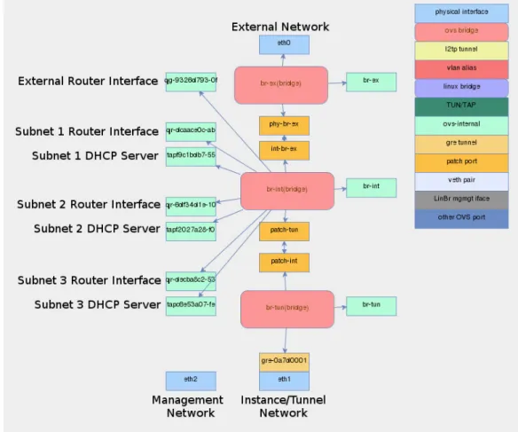
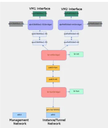
OpenStack implements the virtual network infrastructure (VNI) exploit-ing multiple virtual bridges connectexploit-ing virtual and/or physical interfaces that may reside in different network namespaces. To better understand such a complex system, a graphical tool was developed to display all the network elements used by OpenStack [31]. Two examples, showing the internal state of a network node connected to three virtual subnets and a compute node running two VMs, are displayed in Figs. 2.2 and 2.3, respectively.
Each node runs an OVS-based integration bridge named br-int and, con-nected to it, an additional OVS bridge for each data center physical network attached to the node. So the network node (Fig. 2.2) includes br-tun for the instance/tunnel network andbr-ex for the external network. Three OVS bridges (red boxes) are interconnected by patch port pairs (orange boxes).
br-ex is directly attached to the external network physical interface (eth0), whereas a GRE tunnel is established on the instance/tunnel network physical interface (eth1) to connectbr-tun with its counterpart in the compute node. A number of br-int ports (light-green boxes) are connected to four virtual router interfaces and three DHCP servers. An additional physical interface (eth2) connects the network node to the management network.
A compute node (Fig. 2.3) includes br-tun only. Two Linux Bridges (blue boxes) are attached to the VM tap interfaces (green boxes) and connected by virtual Ethernet pairs (light-blue boxes) to br-int.
Layer 2 virtualization and multi-tenant isolation on the physical network can be implemented using either VLANs or layer-2-in-layer-3/4 tunneling solutions, such as Virtual eXtensible LAN (VXLAN) or Generic Routing Encapsulation (GRE), that allow to extend the local virtual networks also to remote data centers [30]. The examples shown in Figs. 2.2 and 2.3 re-fer to the case of tenant isolation implemented with GRE tunnels on the instance/tunnel network. Whatever virtualization technology is used in the physical network, its virtual networks must be mapped into the VLANs used
Figure 2.2: Network elements in an OpenStack network node connected to three virtual subnets.
Figure 2.3: Network elements in an OpenStack compute node running two VMs.
internally by Neutron to achieve isolation. This is performed by taking ad-vantage of the programmable features available in OVS through the insertion of appropriate OpenFlow mapping rules in br-int and br-tun.
Virtual bridges are interconnected by means of either virtual Ethernet (veth) pairs or patch port pairs, consisting of two virtual interfaces that act as the endpoints of a pipe: anything entering one endpoint always comes out on the other side.
From the networking point of view the creation of a new VM instance involves the following steps:
• the OpenStack scheduler component running in the controller node chooses the compute node that will host the VM;
• a tap interface is created for each VM network interface to connect it to the Linux kernel;
• a Linux Bridge dedicated to each VM network interface is created (in Fig. 2.3 two of them are shown) and the corresponding tap interface is attached to it;
• a veth pair connecting the new Linux Bridge to the integration bridge is created.
The veth pair clearly emulates the Ethernet cable that would connect the two bridges in real life. Nonetheless, why the new Linux Bridge is needed is not intuitive, as the VM’s tap interface could be directly attached to br-int. In short, the reason is that the anti-spoofing rules currently implemented by Neutron adopt the native Linux kernel filtering functions (netfilter) applied to bridged tap interfaces, which work only under Linux Bridges. Therefore, the Linux Bridge is required as an intermediate element to interconnect the VM to the integration bridge. The security rules are applied in the Linux bridge on the tap interface that connects the kernel-level bridge to the virtual Ethernet port of the VM running in user-space.
2.3
Experimental Testbed
The previous section makes clear the complexity of the OpenStack virtual network infrastructure. To understand optimal design strategies in terms on network performance it is of great importance to analyze it under criti-cal traffic conditions and assess the maximum sustainable packet rate under different application scenarios. The goal is to isolate as much as possible the level of performance of the main OpenStack network components and
determine where the bottlenecks are located, speculating on possible im-provements. To this purpose, a test-bed including a controller node, one or two compute nodes (depending on the specific experiment), and a network node was deployed and used to obtain the results presented in the following. In the test-bed each compute node runs KVM, the native Linux VM Hyper-visor, and is equipped with 8 GB of RAM and a quad-core processor enabled to hyper-threading, resulting in 8 virtual CPUs.
The test-bed was configured to implement three possible use cases: 1. a typical single-tenant cloud computing scenario;
2. a multi-tenant NFV scenario with dedicated network functions; 3. a multi-tenant NFV scenario with shared network functions.
For each use case multiple experiments were executed as reported in the following. In the various experiments typically a traffic source sends packets at increasing rate to a destination that measures the received packet rate and throughput. To this purpose the RUDE & CRUDE tool was used, both for traffic generation and measurement [32]. In some cases, the Iperf3
tool was also added to generate background traffic at a fixed data rate [33]. All physical interfaces involved in the experiments were Gigabit Ethernet network cards.
2.3.1
Single-tenant cloud computing scenario
This is the typical configuration where a single tenant runs one or multiple VMs that exchange traffic with one another in the cloud or with an external host, as shown in Fig. 2.4. This is a rather trivial case of limited general interest but is useful to assess some basic concepts and pave the way to the deeper analysis developed in the second part of this section. In the experiments reported, as mentioned above, the virtualization Hypervisor was always KVM. A scenario with Openstack running the cloud environment and a scenario without OpenStack were considered to assess some general comparison and allow a first isolation of the performance degradation due to the individual building blocks, in particular Linux Bridge and OVS. The experiments report the following cases:
1. OpenStack scenario, which adopts the standard OpenStack cloud plat-form, as described in the previous section, with two VMs respectively acting as sender and receiver. In particular, the following setups were tested:
Figure 2.4: Reference logical architecture of a single-tenant virtual infras-tructure with 5 hosts: 4 hosts are implemented as VMs in the cloud and are interconnected via the OpenStack layer-2 virtual infrastructure; the 5th host is implemented by a physical machine placed outside the cloud, but still connected to the same logical LAN.
(1.1) a single compute node executing two co-located VMs;
(1.2) two distinct compute nodes, each executing a VM.
2. Non-OpenStack scenario, which adopts physical hosts running Linux-Ubuntu Server and KVM hypervisor, using either OVS or Linux Bridge as a virtual switch. The following setups were tested:
(2.1) one physical host executing two co-located VMs, acting as sender
and receiver and directly connected to the same Linux Bridge;
(2.2) same setup as the previous one, but with an OVS bridge instead
of a Linux Bridge;
(2.3) two physical hosts: one executing the sender VM connected to
an internal OVS, the other natively acting as the receiver.
2.3.2
Multi-tenant NFV scenario
with dedicated network functions
The multi-tenant scenario we want to analyze is inspired by a simple NFV case-study, as illustrated in Fig. 2.5: each tenant’s service chain consists of a customer-controlled VM followed by a dedicated deep packet inspection (DPI) virtual appliance, and a conventional gateway (router) connecting the customer LAN to the public Internet. The DPI is deployed by the service operator as a separate VM with two network interfaces, running a traffic monitoring application based on the nDPI library [34]. It is assumed that
Figure 2.5: Multi-tenant NFV scenario with dedicated network functions tested on the OpenStack platform.
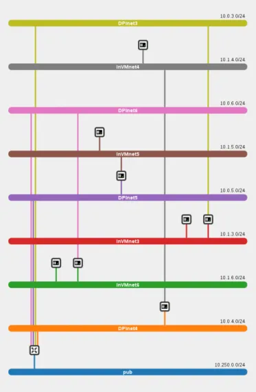
the DPI analyzes the traffic profile of the customers (source and destination IP addresses and ports, application protocol, etc.) to guarantee the matching with the customer service level agreement (SLA), a practice that is rather common among Internet service providers to enforce network security and traffic policing. The virtualization approach executing the DPI in a VM makes it possible to easily configure and adapt the inspection function to the specific tenant characteristics. For this reason every tenant has its own DPI with dedicated configuration. On the other hand the gateway has to implement a standard functionality and is shared among customers. It is implemented as a virtual router for packet forwarding and NAT operations. The implementation of the test scenarios has been done following the OpenStack architecture. The compute nodes of the cluster run the VMs, while the network node runs the virtual router within a dedicated network namespace. All layer-2 connections are implemented by a virtual switch (with proper VLAN isolation) distributed in both the compute and network nodes. Figure 2.6 shows the view of the cluster setup provided by the OpenStack dashboard, in the case of 4 tenants simultaneously active, which is the one considered for the numerical results presented in the following. Each slice includes a VM connected to an internal network (InVMneti) and a second VM performing DPI and packet forwarding between InVMnetiand DPIneti. Connectivity with the public Internet is provided for all by the virtual router in the bottom-left corner of the figure. The choice of 4 tenants was made to provide meaningful results with an acceptable degree of complexity, without lack of generality. As results shows this is enough to put the hardware re-sources of the compute node under stress and therefore evaluate performance limits and critical issues.
It is very important to outline that the VM setup shown in Fig. 2.5 is not commonly seen in a traditional cloud computing environment. The VMs usually behave as single hosts connected as end-points to one or more virtual networks, with one single network interface and no pass-through forwarding duties. In NFV the virtual network functions (VNFs) often perform actions
Figure 2.6: The OpenStack dashboard shows the tenants virtual networks (slices).
that require packet forwarding. Network Address Translators (NATs), Deep Packet Inspectors (DPIs), etc. all belong to this category. If such VNFs are hosted in VMs the result is that VMs in the OpenStack infrastructure must be allowed to perform packet forwarding which goes against the typical rules implemented for security reasons in OpenStack. For instance when a new VM is instantiated it is attached to a Linux bridge to which are applied filtering rules with the goal to avoid that the VM sends packet with MAC and IP addresses that are not the ones allocated to the VM itself. Clearly this is an anti-spoofing rule that makes perfect sense in a normal networking environment but impairs the forwarding of packets originated by another VM as is the case of the NFV scenario. In the scenario considered here, it was therefore necessary to permanently modify the filtering rules in the Linux bridges, by allowing, within each tenant slice, packets coming from or directed to the customer VM’s IP address to pass through the Linux Bridges attached to the DPI virtual appliance. Similarly the virtual router is usually connected just to one LAN. Therefore its NAT function is configured for a single pool of addresses. This was also modified and adapted to serve the whole set of internal networks used in the multi-tenant setup.
2.3.3
Multi-tenant NFV scenario
with shared network functions
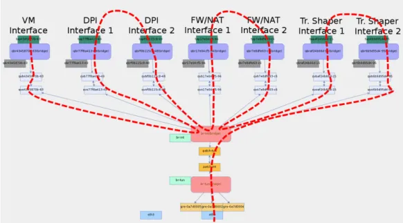
We finally extend our analysis to a set of multi-tenant scenarios assuming dif-ferent levels of shared VNFs, as illustrated in Fig. 2.7. We start with a single VNF, i.e. the virtual router connecting all tenants to the external network (Fig. 2.7a). Then we progressively add a shared DPI (Fig. 2.7b), a shared firewall/NAT function (Fig. 2.7c) and a shared traffic shaper (Fig. 2.7d). The rationale behind this last group of setups is to evaluate how a NFV deployment on top of an OpenStack compute node performs under a real-istic multi-tenant scenario where traffic flows must be processed by a chain of multiple VNFs. The complexity of the virtual network path inside the compute node for the VNF chaining of Fig. 2.7d is displayed in Fig. 2.8. The peculiar nature of NFV traffic flows is clearly shown in the figure, where packets are being forwarded multiple times across br-int as they enter and exit the multiple VNFs running in the compute node. The red dashed line shows the path followed by the packets traversing the VNF chain displayed in Fig. 2.7d.
(a) Single VNF.
(b) Two VNFs chaining.
(c) Three VNFs chaining.
(d) Four VNFs chaining.
Figure 2.7: Multi-tenant NFV scenario with shared network functions tested on the OpenStack platform.
Figure 2.8: A view of the OpenStack compute node with the tenant VM and the VNFs installed including the building blocks of the Virtual Network Infrastructure.
2.4
OpenStack performance:
numerical results
2.4.1
Benchmark performance
Before presenting and discussing the performance of the study scenarios de-scribed above, it is important to set some benchmark as a reference for com-parison. This was done by considering a back-to-back (B2B) connection between two physical hosts, with the same hardware configuration used in the cluster of the cloud platform.
The former host acts as traffic generator while the latter acts as traffic sink. The aim is to verify and assess the maximum throughput and sustain-able packet rate of the hardware platform used for the experiments. Packet flows ranging from 103 to 105 packets per second (pps), both for 64 and
1500-byte IP packet sizes were generated.
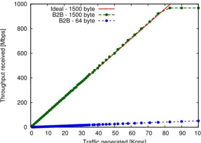
For 1500-byte packets, the throughput saturates to about 970 Mbps at 80 Kpps. Given that the measurement does not consider the Ethernet overhead, this limit is clearly very close to the 1 Gbps which is the physical limit of the Ethernet interface. For 64-byte packets, the results are different since the maximum measured throughput is about 150 Mbps. Therefore the limiting
0 200 400 600 800 1000 0 10 20 30 40 50 60 70 80 90 100 Throughput received [Mbps] Traffic generated [Kpps] Ideal - 1500 byte B2B - 1500 byte B2B - 64 byte
Figure 2.9: Throughput vs. generated packet rate in the B2B setup for 64 and 1500-byte packets. Comparison with ideal 1500-byte packet throughput. factor is not the Ethernet bandwidth, but the maximum sustainable packet processing rate of the computer node. These results are shown in Fig. 2.9.
This latter limitation, related to the processing capabilities of the hosts, is not very relevant to the scopes of this work. Indeed it is always possible, in a real operation environment, to deploy more powerful and better dimen-sioned hardware. This was not possible in this set of experiments where the cloud cluster was an existing research infrastructure which could not be mod-ified at will. Nonetheless the objective here is to understand the limitations that emerge as a consequence of the networking architecture, resulting from the deployment of the VNFs in the cloud, and not of the specific hardware configuration. For these reasons as well as for the sake of brevity, the numer-ical results presented in the following mostly focus on the case of 1500-byte packet length, which will stress the network more than the hosts in terms of performance.
2.4.2
Single-tenant cloud computing scenario
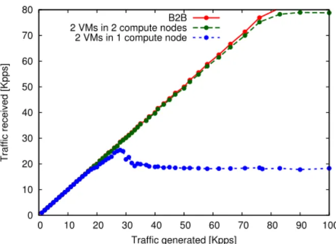
The first series of results is related to the single-tenant scenario described in section 2.3.1. Figure 2.10 shows the comparison of OpenStack setups (1.1) and (1.2) with the B2B case. The figure shows that the different networking configurations play a crucial role on performance. Setup (1.1) with the two VMs co-located in the same compute node clearly is more demanding since the compute node has to process the workload of all the components shown in Fig. 2.3, i.e. packet generation and reception in two VMs and layer 2 switching in two Linux Bridges and two OVS bridges (as a matter of fact
0 10 20 30 40 50 60 70 80 0 10 20 30 40 50 60 70 80 90 100 Traffic received [Kpps] Traffic generated [Kpps] B2B 2 VMs in 2 compute nodes 2 VMs in 1 compute node
Figure 2.10: Received vs. generated packet rate in the OpenStack scenario setups (1.1) and (1.2), with 1500-bytes packets.
the packets are either outgoing and incoming at the same time within the same physical machine). The performance starts deviating from the B2B case at around 20 Kpps, with a saturating effect starting at 30 Kpps. This is the maximum packet processing capability of the compute node, regardless the physical networking capacity, which is not fully exploited in this partic-ular scenario where the traffic flow does not leave the physical host. Setup (1.2) splits the workload over two physical machines and the benefit is evi-dent. The performance is almost ideal, with a very little penalty due to the virtualization overhead.
These very simple experiments lead to an important conclusion that mo-tivates the more complex experiments that follow: the standard OpenStack virtual network implementation can show significant performance limitations. For this reason the first objective was to investigate where the possible bot-tleneck is, by evaluating the performance of the virtual network components in isolation. This cannot be done with OpenStack in action, therefore ad-hoc virtual networking scenarios were implemented deploying just parts of the typical OpenStack infrastructure. These are called Non-OpenStack sce-narios in the following.
Setups (2.1) and (2.2) compare Linux Bridge, OVS and B2B, as shown in Figure 2.11. The graphs show interesting and important results that can be summarized as follows:
• the introduction of some virtual network component (thus introducing the processing load of the physical hosts in the equation) is always a cause of performance degradation but with very different degrees of magnitude depending on the virtual network component;
0 10 20 30 40 50 60 70 80 0 10 20 30 40 50 60 70 80 90 100 Traffic received [Kpps] Traffic generated [Kpps] B2B 2 VMs with OVS 2 VMs with LB
Figure 2.11: Received vs. generated packet rate in the Non-OpenStack sce-nario setups (2.1) and (2.2), with 1500-bytes packets.
• OVS introduces a rather limited performance degradation at very high packet rate with a loss of some percent;
• Linux Bridge introduces a significant performance degradation starting well before the OVS case and leading to a loss in throughput as high as 50%.
The conclusion of these experiments is that the presence of additional Linux Bridges in the compute nodes is one of the main reasons of the OpenStack performance degradation. Results obtained from testing setup (2.3) are dis-played in Fig. 2.12 confirming that with OVS it is possible to reach perfor-mance comparable with the baseline.
2.4.3
Multi-tenant NFV scenario
with dedicated network functions
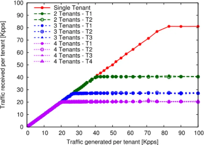
The second series of experiments was performed with reference to the multi-tenant NFV scenario with dedicated network functions described in section 2.3.2. The case study considers that different numbers of tenants are hosted in the same compute node, sending data to a destination outside the local LAN, therefore beyond the virtual gateway. Figure 2.13 shows the packet rate actually received at the destination for each tenant, for different numbers of simultaneously active tenants with 1500 byte IP packet size. In all cases the tenants generate the same amount of traffic, resulting in as many overlapping curves as the number of active tenants. All curves grow linearly as long as the generated traffic is sustainable, and then they saturate. The saturation
0 10 20 30 40 50 60 70 80 0 10 20 30 40 50 60 70 80 90 100 Traffic received [Kpps] Traffic generated [Kpps] B2B
OVS with Sender VM only
Figure 2.12: Received vs. generated packet rate in the Non-OpenStack sce-nario setup (2.3), with 1500-bytes packets.
is caused by the physical bandwidth limit imposed by the Gigabit Ethernet interfaces involved in the data transfer. In fact, the curves become flat as soon as the packet rate reaches about 80 Kpps for 1 tenant, about 40 Kpps for 2 tenants, about 27 Kpps for 3 tenants, and about 20 Kpps for 4 tenants, i.e. when the total packet rate is slightly more than 80 Kpps, corresponding to 1 Gbps. 0 10 20 30 40 50 60 70 80 90 100 0 10 20 30 40 50 60 70 80 90 100
Traffic received per tenant [Kpps]
Traffic generated per tenant [Kpps] Single Tenant 2 Tenants - T1 2 Tenants - T2 3 Tenants - T1 3 Tenants - T2 3 Tenants - T3 4 Tenants - T1 4 Tenants - T2 4 Tenants - T3 4 Tenants - T4
Figure 2.13: Received vs. generated packet rate for each tenant (T1, T2, T3 and T4), for different numbers of active tenants, with 1500-byte IP packet size.
In this case it is worth investigating what happens for small packets, therefore putting more pressure on the processing capabilities of the com-pute node. Figure 2.14 reports the 64-byte packet size case. As discussed
0 10 20 30 40 50 60 70 80 90 100 0 10 20 30 40 50 60 70 80 90 100
Traffic received per tenant [Kpps]
Traffic generated per tenant [Kpps] Single Tenant 2 Tenants - T1 2 Tenants - T2 3 Tenants - T1 3 Tenants - T2 3 Tenants - T3 4 Tenants - T1 4 Tenants - T2 4 Tenants - T3 4 Tenants - T4
Figure 2.14: Received vs. generated packet rate for each tenant (T1, T2, T3 and T4), for different numbers of active tenants, with 64-byte IP packet size. previously in this case the performance saturationis not caused by the physi-cal bandwidth limit, but by the inability of the hardware platform to cope with the packet processing workload.2 As could be easily expected from the results presented in Fig. 2.9, the virtual network is not able to use the whole phys-ical capacity. Even in the case of just one tenant, a total bit rate of about 77 Mbps, well below 1 Gbps, is measured. Moreover this penalty increases with the number of tenants (i.e., with the complexity of the virtual system). With two tenants the curve saturates at a total of approximately 150 Kpps (75×2), with three tenants at a total of approximately 135 Kpps (45×3), and with four tenants at a total of approximately 120 Kpps (30×4). This is to say that an increase of one unit in the number of tenants results in a decrease of about 10% in the usable overall network capacity and in a similar penalty per tenant.
Given the results of the previous section, it is likely that the Linux bridges are responsible for most of this performance degradation. In Fig. 2.15 a comparison is presented between the total throughput obtained under normal OpenStack operations and the corresponding total throughput measured in a custom configuration where the Linux Bridges attached to each VM are bypassed. To implement the latter scenario, the OpenStack virtual network configuration running in the compute node was modified by connecting each VM’s tap interface directly to the OVS integration bridge. The curves show that the presence of Linux Bridges in normal OpenStack mode is indeed
2In fact the single compute node has to process the workload of all the components
involved, including packet generation and DPI in the VMs of each tenant, as well as layer-2 packet processing and switching in three Linux Bridges per tenant and two OVS bridges.
0 10 20 30 40 50 60 70 80 90 100 0 50 100 150 200 250 300 350 400
Total throughput received [Mbps]
Total traffic generated [Kpps] 3 Tenants (LB bypass) 4 Tenants (LB bypass) 2 Tenants 3 Tenants 4 Tenants
Figure 2.15: Total throughput measured vs. total packet rate generated by 2 to 4 tenants for 64-byte packet size. Comparison between normal OpenStack mode and Linux Bridge bypass with 3 and 4 tenants.
causing performance degradation, especially when the workload is high (i.e., with 4 tenants). It is interesting to note also that the penalty related to the number of tenants is mitigated by the bypass, but not fully solved.
2.4.4
Multi-tenant NFV scenario
with shared network functions
The third series of experiments was performed with reference to the multi-tenant NFV scenario with shared network functions described in section 2.3.3. In each experiment, four tenants are equally generating increasing amounts of traffic, ranging from 1 to 100 Kpps. Figures 2.16 and 2.17 show the packet rate actually received at the destination from tenant T1 as a function of the packet rate generated by T1, for different levels of VNF chaining, with 1500 and 64-byte IP packet size respectively. The VNFs and sink involved in the chain are: DPI (deep packet inspection), FW (firewall/NAT), TS (traffic shaper), VR (virtual router) and DEST (destination/sink). The measure-ments demonstrate that, for the 1500-byte case, adding a single shared VNF (even one that executes heavy packet processing, such as the DPI) does not significantly impact the forwarding performance of the OpenStack compute node for a packet rate below 50 Kpps.3 Then the throughput slowly degrades. In contrast, when 64-byte packets are generated, even a single VNF can cause
3Note that the physical capacity is saturated by the flows simultaneously generated
from four tenants at around 20 Kpps, similarly to what happens in the dedicated VNF case of Fig. 2.13.
0 10 20 30 40 50 0 10 20 30 40 50 60 70 80 90 100 Traffic received [Kpps] Traffic generated [Kpps] T1-VR-DEST T1-DPI-VR-DEST T1-DPI-FW-VR-DEST T1-DPI-FW-TS-VR-DEST
Figure 2.16: Received vs. generated packet rate for one tenant (T1) when four tenants are active, with 1500-byte IP packet size and different levels of VNF chaining as per Fig. 2.7.
heavy performance losses above 25 Kpps, when the packet rate reaches the sustainability limit of the forwarding capacity of our compute node. Inde-pendently of the packet size, adding another VNF with heavy packet pro-cessing (the firewall/NAT is configured with 40,000 matching rules) causes the performance to rapidly degrade. This is confirmed when a fourth VNF is added to the chain, although for the 1500-byte case the measured packet rate is the one that saturates the maximum bandwidth made available by the traffic shaper. Very similar performance, which we do not show here, were measured also for the other three tenants.
To further investigate the effect of VNF chaining, we considered the case when traffic generated by tenant T1 is not subject to VNF chaining (as in Fig. 2.7a), whereas flows originated from T2, T3 and T4 are processed by four VNFs (as in Fig. 2.7d). The results presented in Figs. 2.18 and 2.19 demonstrate that, owing to the traffic shaping function applied to the other tenants, the throughput of T1 can reach values not very far from the case when it is the only active tenant, especially for packet rates below 35 Kpps. Therefore, a smart choice of the VNF chaining and a careful planning of the cloud platform resources could improve the performance of a given class of priority customers. In the same situation, we measured the TCP throughput achievable by the four tenants. As shown in Fig. 2.20, we can reach the same conclusions as in the UDP case.
0 10 20 30 40 50 0 10 20 30 40 50 60 70 80 90 100 Traffic received [Kpps] Traffic generated [Kpps] T1-VR-DEST T1-DPI-VR-DEST T1-DPI-FW-VR-DEST T1-DPI-FW-TS-VR-DEST
Figure 2.17: Received vs. generated packet rate for one tenant (T1) when four tenants are active, with 64-byte IP packet size and different levels of VNF chaining as per Fig. 2.7.
0 100 200 300 400 500 600 700 800 900 0 10 20 30 40 50 60 70 80 90 100 Throughput received [Mbps] Traffic generated [Kpps] T1-VR-DEST single tenant T1-VR-DEST
T2-DPI-FW-TS-VR-DEST T3-DPI-FW-TS-VR-DEST T4-DPI-FW-TS-VR-DEST
Figure 2.18: Received throughput vs. generated packet rate for each tenant (T1, T2, T3 and T4) when T1 does not traverse the VNF chain of Fig. 2.7d, with 1500-byte IP packet size. Comparison with the single tenant case.
0 10 20 30 40 50 60 0 10 20 30 40 50 60 70 80 90 100 Throughput received [Mbps] Traffic generated [Kpps] T1-VR-DEST single tenant T1-VR-DEST
T2-DPI-FW-TS-VR-DEST T3-DPI-FW-TS-VR-DEST T4-DPI-FW-TS-VR-DEST
Figure 2.19: Received throughput vs. generated packet rate for each tenant (T1, T2, T3 and T4) when T1 does not traverse the VNF chain of Fig. 2.7d, with 64-byte IP packet size. Comparison with the single tenant case.
0 200 400 600 800 1000 0 20 40 60 80 100 120 TCP throughput received [Mbps] Time [s]
T1-VR-DEST single tenant T1-VR-DEST T2-DPI-FW-TS-VR-DEST T3-DPI-FW-TS-VR-DEST T4-DPI-FW-TS-VR-DEST
Figure 2.20: Received TCP throughput for each tenant (T1, T2, T3 and T4) when T1 does not traverse the VNF chain of Fig. 2.7d. Comparison with the single tenant case.
2.5
Conclusion
Network Function Virtualization will completely reshape the approach of telco operators to provide existing as well as novel network services, tak-ing advantage of the increased flexibility and reduced deployment costs of the cloud computing paradigm. In this work, the problem of evaluating complexity and performance, in terms of sustainable packet rate, of virtual networking in cloud computing infrastructures dedicated to NFV deploy-ment was addressed. An OpenStack-based cloud platform was considered and deeply analyzed to fully understand the architecture of its virtual net-work infrastructure. To this end, an ad-hoc visual tool was also developed that graphically plots the different functional blocks (and related intercon-nections) put in place by Neutron, the OpenStack networking service.
The analysis brought the focus of the performance investigation on the two basic software switching elements natively adopted by OpenStack, namely Linux Bridge and Open vSwitch. Their performance was first analyzed in a single-tenant cloud computing scenario, by running experiments on a stan-dard OpenStack setup as well as in ad-hoc stand-alone configurations built with the specific purpose to observe them in isolation. The results prove that the Linux Bridge is the critical bottleneck of the architecture, while Open vSwitch shows an almost optimal behavior.
The analysis was then extended to more complex scenarios, assuming a data center hosting multiple tenants deploying NFV environments. The case studies considered first a simple dedicated deep packet inspection function, followed by conventional address translation and routing, and then a more realistic virtual network function chaining shared among a set of customers with increased levels of complexity. Results about sustainable packet rate and throughput performance of the virtual network infrastructure were presented and discussed.
The main outcome of this work is that an open-source cloud computing platform such OpenStack can be effectively adopted to deploy NFV in net-work edge data centers replacing legacy telco central offices. However, this solution poses some limitations to the network performance which are not simply related to the hosting hardware maximum capacity, but also to the virtual network architecture implemented by OpenStack. Nevertheless, our study demonstrates that some of these limitations can be mitigated with a careful re-design of the virtual network infrastructure and an optimal plan-ning of the virtual network functions. In any case, such limitations must be carefully taken into account for any engineering activity in the virtual networking arena.
study of how to implement a NFV use case on the OpenStack platform, we moved our attention on the control plane of the network. In particular,we focused on the Service Function Chaining mechanism, which is considered one of the crucial network capability from an operational efficiency point of view for a telecommunication operator. Design and evaluation aspects on implementing dynamic NFV are investigated and discussed in chapter 3.