P.O. Box 513, 5600 MB Eindhoven The Netherlands
http://w3.ele.tue.nl/nl/
Series title:
Master graduation paper, Electrical Engineering
Commissioned by Professor: Group / Chair:
Date of final presentation: Report number:
Nicola Calabretta
IPI-ECO Research Institute
SDN-based control and
orchestration of optical data centre
network
7th June 2019
Internal supervisors: Nicola Calabretta External supervisors: Salvatore Spadaro
by
Abstract
The use of the Internet is linked with the constant technological change that the world is suffering nowadays, which is responsible for the important need to update the infrastructure of current data centers. The amount of traffic that is moving in data centers has increased significantly in the past few years, so a better alternative for them should be studied, as the use of Ethernet or InfiniBand is no longer appropriate in terms of scalability and flexibility.
Optical technology is one possible solution for it, as it provides a big bandwidth, low latency and an overall better performance. However, the physical resources that form a data center should be managed in an efficient way. To perform an optimum use of them, the new concept of virtual data center appeared, where the orchestration of the resources is done with the aim of offering to a cloud infrastructure to a third party. In this context, OpenStack has become one of the most popular open source platforms when building public or private clouds, based on three important aspects: compute, storage and network. But the flexibility of these cloud infrastructures is attached to being scalable or dynamic. In this case, Software Definiton Network (SDN) and Network Function Virtualization (NFV) play an important role in data centers, as they allow to build complex network capabilities on demand.
In this project, we experimentally demonstrate the programmable OPsquare data center network empowered by an SDN control plane. The implementation is based on monitoring the real-time statistics of the network, so some actions such as network slices provisioning and reconfiguration, packet priority class assignment or dynamic load balancing operations can be done in order to achieve the required Quality of Service level.
This project is a cooperation between TU/e (Eindhoven University of Technology, The Netherlands) and UPC (Universitat Politècnica de Catalunya, Barcelona).
Acknowledgments
In the first place, I would like to thank both of the supervisors of this project: Nicola Calabretta and Salvatore Spadaro, for the help and support that gave to me during the development of it. Working close to professional people in the electro-optical communication field helped me to gain knowledge of that sector and be able to apply it in the project, as well as in resolving methods to problems I faced during the development. I can’t thank them enough, without its help this project would not have arrived until this point.
Moreover, I would also like to thank some of the teachers and PhD students of TU/e and UPC for all the material and information provided for the project. Xuwei Xue, Fu Wang, Fernando Agraz and Rafael, thank you very much.
Finally, I would like to appreciate my family’s support that they gave to me during my exchange period in The Netherlands and, what is more important, to encourage me.
CONTENTS
1. INTRODUCTION 10
1.1. DATA CENTERS 10
1.2. OPTICAL FIBER TECHNOLOGY 12
1.3. EVOLUTION OF DATA CENTERS 14
1.4. TRANSPORT TECHNOLOGIES 15
2. NETWORK PROGRAMMABILITY 16
2.1. TRADITIONAL NETWORKS 16
2.2. APPLICATION PROGRAMMING INTERFACES (APIS) 17
2.3. VIRTUAL DATA CENTER 20
2.4. THE ORCHESTRATION LAYER 21
3. OUR SCENARIO 23
3.1. TOOLS NEEDED 23
3.1.1. OPENDAYLIGHT: THE SDN CONTROLLER 23
3.1.2. OPENSTACK: THE ORCHESTRATOR 24
3.2. ORCHESTRATED SDN-ENABLED OPSQUARE DCN 25
3.3. THE IMPLEMENTATION 27
3.3.1. FIRST APPROACH 27
3.3.2. SECOND APPROACH 27
4. THE RESULTS 32
4.1. PATH COMPUTATION ENGINE 34
5. CONCLUSIONS 36
6. REFERENCES 37
List of abbreviations
DC: Data CenterDCN: Data Center Network
FPGA: Field Programmable Gate Arrays ME: Monitoring Engine
MM: Monitoring Manager
NFV: Network Function Virtualization NS: Network Slices
ODL: OpenDaylight OF: OpenFlow
OFC: Optical Flow Control
OPM: Optical Provisioning Manager OPS: Optical Switch
PCE: Path Computation Engine SDN: Software Definition Network TM: Topology Manager
ToR: Top of Rack
VDC: Virtual Data Center VM: Virtual Machine VN: Virtual Network QoS: Quality of Service
1.
Introduction
1.1. Data Centers
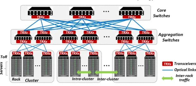
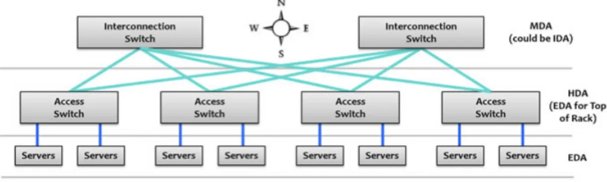
The Data Center infrastructures (DC) are a fundamental piece in the current telecommunication systems and cloud services, allowing the users to access to huge amounts of data. In the traditional DC’s, the servers are organized in racks. Each racks is composed by a ToR (Top of the Rack) switch which interconnects the different servers and allows the exchange of information between racks through a network called intra-DC (DCN). In this kind of network, electrical switches are used in a way that provides redundancy to have a better usage of network resources and to guarantee the QoS required.
However, the rise of cloud computing, big data services and IoT (Internet of Things) has significantly increased the traffic in the data centers. The key requirements for data center networks are:
• Latency: time that a packets need to traverse the network from the source to
the destination node, including the propagation and switch latency.
• Capacity: if full-bandwidth communication is desired between the servers, a
high internal capacity of it is required.
• Scalability: the rise of this infrastructures is expected to continue growing over
the next few years. The DC should enable to scale a high number of nodes to address future capacity needs in an efficient way.
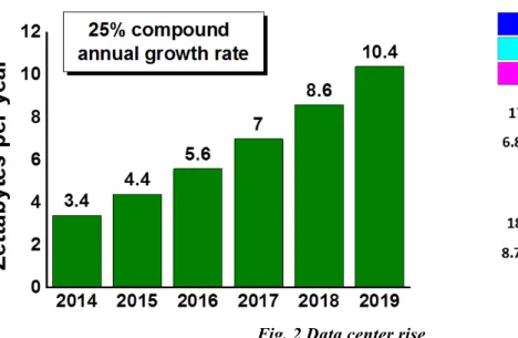
Fig. 2 Data center rise
• Flexibility: using virtualization services, DC should be able to adapt to new
changes in a quickly way. For example, the adoption of new standards or protocols in order to seed up the deployment of networks.
• Power/cost-efficiency: in order to keep the energy costs as minimum as
possible, there is an important need to think about power-efficiency. Optical technology and virtualization networks are used in that sense.
Because all of this factors, the rise of DC should be well prepared and managed. As
shown in
Fig. 2
, we can see the traffic growth in data centers from 2014 to 2019.However we can see that the traffic that is happening within them is not changing significantly from 2014 to 2019. In this sense, data centers are growing in terms of size and complexity, in other words, in the increase of demands for more powerful computational performance, which can be managed using NFV (Network Functions Virtualization) allowing an efficient use of the resources shared on the same infrastructure.
For this reason, the use of electrical switches in the tradition DCN structures is coming to an end. So there is an important need to improve the intra-DCN deployed in the future data centers. Taking this fact into account combined with the previous mentioned key requirements for a DC, one of the possible solutions that is being really used nowadays is the optical fiber technology.
1.2. Optical fiber technology
Fiber-optic technology has popular since several years ago and is known for some characteristics. The wave-guide being more used is the fiber-optic, which has been successful due to two main reasons:
• Low attenuation: currently the systems without amplification allow distances
close to 100km, and systems with amplification allow intercontinental communication (submarine cabling).
• High bandwidth: allows the transmission at high speeds. Nowadays, there are
laboratory experiments that allow transmissions around 3.2 Terabits per second.
So, as an overview, fiber optic technology allows fast transmission of data, is made of glass and works as a waveguide to transmit light between two nodes. Fiber optic has been used in long distances scenarios such as an intercontinental connection. However, in the past few years it is also becoming more popular in Ethernet LAN networks. The reason for this is because of the fast speeds that can reach and because immunity to interferences, like cross-talk.
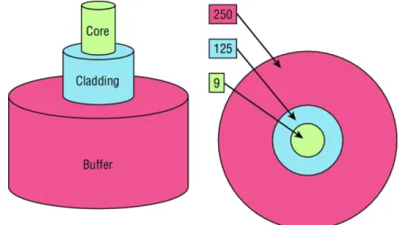
The fiber optic is composed of two important parts: the core and the cladding. The core holds the light and the cladding confines the light in the core. If the cladding is small, the core is small too. So, when the core is small, less light will be sent through but the speed and the distance will be higher.
In the
Fig. 3
it is shown the composition of this technology. In this case, there is a smallcore (9-micron), which can be compared as human hair (50 microns).
The cladding of 125 microns is a fiber standard well known by different manufacturers to make standardized connectors. The buffer is in charge to protect the fiber glass.
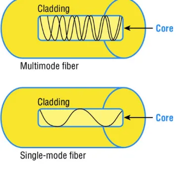
There are two types of fiber optic: single-mode and multimode. In
Fig. 4
we can see thedifferences between both types.
Let’s state the differences between both types:
Table 1 Differences between single-mode and multi-mode
Single-mode Multi-mode
Expensive Cheap
Small core Large core
Farther distances Less distances
The single-mode fiber optic has a small core, which means that it will allow only one light mode to be propagated through it, reaching higher distances. However, the multi-mode one has a large core, so multiple light multi-modes will propagate through it.
1.3. Evolution of Data Centers
A clear drawback of the intra-DCN network shown in
Fig. 1
are the bottlenecks thatcan be found in the first access level to them, also known as core switch. This switches route the traffic that comes from or to the data center. A bottleneck can be observed in case there is not enough bandwidth due to the high amount of traffic between the switches. The first level of switches (core switches) are connected to the aggregation switches, which are connected to the access switches (usually located on the Top of the Rack (ToR) with servers). The traffic that goes between these different type of switches generate a high latency when transmitting information and a significant cabling distance, which is not an ideal condition in virtual environments. Another possible bottleneck could be related to the electrical process that perform Ethernet cables. That’s why fiber optic technology is used.
Therefore, there is a need for an evolution of the traditional DC architectures in order to keep correctly the key requirements mentioned in previous sections: low latency between switches and high bandwidth to try to support the maximum capacity and so, reach the maximum speed.
Fig. 5
shows an horizontal way to send traffic between switches, instead of the verticalone proposed in
Fig. 1
. In this new evolution of DC, fiber optic is a must in order to setthe architecture with a better scalability, management and flexibility.
Fig. 5 Evolution of DC architecture
The interconnection switches work in a Optical-to-Optical-to-Optical (OOO) technology shown in the previous picture are pure optical switches, without altering the information that is being sent. The access switches work as Optical-to-Electrical-to-Optical (OEO)
switches, despite the fact that they could support optic technology. But as in this case there exist some electric commutations inside the switches, this will lead to a rise of the dissipated heat and a significant reduce of the latency when sending information. So, when some traffic is coming to the switch from the fiber-optic cabling, it is going to be transformed into electrical information and then again to light in order to be sent to the output pot. This is really useful, as two different sources of information destinated to the same output could be combined. In this case, this switches will be the ToR. Finally, these switches will be connected to the servers in the racks, which they will have an electrical communication through Ethernet.
1.4. Transport technologies
Optical transport network increased their use in the last few years. Some reasons could be:
• To adjust to QoS network requirements (high bandwidth and low latency)
• There is a need to cope with the ever-growing Internet traffic
• Energy efficiency, reducing the power consumption
• Flexibility and low operational cost
There are two methods of optical transport:
• Optical Circuit Switching (OCS): light paths are established to carry aggregated
data traffic, achieving a higher bandwidth, scalability and guarantying the QoS requirements. This method is used for long-lived data flows, such as bulk data transfer, HDTV…
• Optical Packet Switching (OPS): in this case, the IP packets are aggregated in
optical packets before being sent to WDM channels, achieving high flexibility and optical flow control. This method is used for short-lived data flows such as VoIP, HPC...
So, we can see that using both types of optical transport technologies, these architectures requires control and management planes, the topic which we will cover in the following section.
2.
Network Programmability
2.1. Traditional networks
Nowadays, routers and switches ports are the only devices that are not virtualized. And it is what is used in traditional networks. In the last few years, there has been a significant increase in the research of how to virtualize the devices physical ports. First of all, it’s important to keep in mind that the current routers and switches run an operating system that provides network functionality. During approximately 25 years, this has been widely used, but the complexity to configure, implement or troubleshoot the devices made to approach it in another way, as current networks are quite large and complex.
Before designing any new approach to design networks, it’s important to understand the business requirements and then carry it out in all the devices. This process can be done in several weeks or months, as the configuration, maintenance and monitoring has to be done separately.
There current networks forward traffic data using two planes:
• Data plane: this plane is responsible for forwarding frames of packets from the
source to the destination interfaces using protocols managed by the control plane. Once the information is received, the destination interface is looked up, so the frames are forwarded in that direction.
• Control plane: this plane is in charge of managing and controlling any
forwarding table that the data plane uses. Routing protocols are included in this plane, such as OSPF or RIP, but also switch MAC address learning and the Spanning Tree Protocol (STP).
To sum up, the data plane relies completely on the control plane when forwarding traffic in traditional networks.
2.2. Application Programming Interfaces (APIs)
In the last decade, enterprise Wi-Fi installations designed physical networks and then configured a type of network controller that managed all the wireless APs in the networks. It’s difficult to think that a company would install a wireless network today without any controller in an enterprise network, where the access points (APs) receive their directions from the controller on how to manage the wireless frames and the APs have no operating system or brains to make any decisions on their own.
A similar situation is true for our physical devices, so this centralized management of frames that are sent in the network and that SDN (Software Definition Network) provides to them.
SDN removes the control plane from each network device. Instead of that, it has a centralized controller that is in charge of managing the network, avoiding the need of having an operating system on each device. Therefore, this controller separated the data and control planes, with the aim to automate the configuration and remediation of each these network devices.
So, using the network programmability tool, we only have one centralized control plane instead of having individual control planes inside the network devices. With this, we consolidate all network operations inside the SDN controller. To control and configure the network without the need of human interactivity, APIs in applications are used, as they make easy the communication and operations between machines.
In
Fig. 6
we can see the difference between the SDN architecture and the traditional one. Now we add a third layer called the application plane:• Data plane: based on the network device that is in charge of sending and
receiving traffic.
• Control plane: based on a software solution, in this plane is where the SDN
controllers lives, providing centralized network management to populate the data plane and removing the control plane of each device.
• Application plane: that’s the new layer of SDN architecture. Here, they reside
the applications that need to communicate to network device by means of the SDN controller using APIs.
As far as we have studied, SDN tool could change a lot the way we see the network in the future, as the applications will say to the network what to do based on the business requirements instead of user manually configuration. The SDN controller will use the APIs to pass the instructions to the physical devices, so this will avoid spending a high amount of time to implement business needs.
About APIs, there are two categories that SDN controller use to communicate. As we
have seen in
Fig. 6
SDN communicates with the application plane, but also with thedata plane. The communication with the data plane is defined with southbound interfaces, but the communications with the applications uses the northbound interface. Southbound APIs
This are defined as device-to-control-plane communication, or as SBI (Logical Southbound interfaces) APIs, so they are used for the communication between the SDN controller and the physical devices of the network. They are really useful, as they allow they controller to program the data plane for example, forwarding tables of the switches.
It’s important to keep in mind that when talking about network programmability using SDN, the term interface is not referred anymore to a physical interface. Instead, it refers to a logical one.
SBI have many standards. Let’s take a look at the most common ones:
• OpenFlow: is the standard used in this project, defined by ONF
(OpenNetworking). Using NETCONF, it can configure flow path in the network or the device’s forwarding table. This is known as an imperative SDN model.
• NETCONF: this is a new way of providing network management protocols by
the IETF. Using RPC, it’s possible to configure the physical devices using XML.
• OpFlex: this is known as a declarative SDN model and it’s the default one used
by Cisco devices, as the controller send an abstract summary policy to the network devices, which they only have a partially centralized management control.
Northbound APIs
This are defined as NBIs (Logical Northbound Interfaces) APIs, allowing the communication between the controller and the different applications.
This type of API makes able the possibility that the application control the network, saving a huge amount of time in comparison when some manual configuration is needed in each physical device.
They include a big amount of services, such as network virtualization, firewall monitoring, access policy control and so on. And what’s more important, they allow the possibility for enabling cloud platforms tools, including virtualized processing and storage.
In this case, there are not common standards as they were with SBIs. So when using NBI, it’s important to choose the correct one that works only with a determined set of applications. For example, REST (Representational State Transfer) is really useful in the past few years, using HTTP to send data through the applications which resides in the different hosts.
2.3. Virtual Data Center
As far as we have seen in the previous sections, SDN technology is not only aimed to provide connectivity, but also a dynamic network infrastructure able to provide, establish and manage complex services. So, SDN allows the network infrastructure virtualization, in which we can define a new term: Network Slicing. Using physical resource abstraction, these network slices are created, which they will need independent management and control to each of them. This concept is the previous to a new one: Virtual Data Centers.
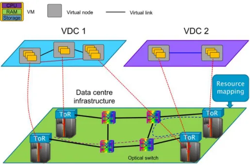
A Virtual Data Center (VDC) service consists in giving a part of the DC infrastructure to a tenant (or an external entity) as a support to develop their own business model. Each VDC consists on a virtual infrastructure which integrates computational capacities as virtual machines. These VMs are interconnected between them through a virtual network (network slice), in where tenants can develop their applications with the main goal to offer a final service to their users. Using VDCs, we open the possibility of different tenants using the same infrastructure but making each one independently of the others and having the whole control and management of its network. All of this network virtualization process is described in the following picture.
This process is complex, but it mainly consists on mapping the VMs into servers in the DC and the virtual links into physical network resources in the DC network. In this context, talking about the orchestrator is key.
2.4. The orchestration layer
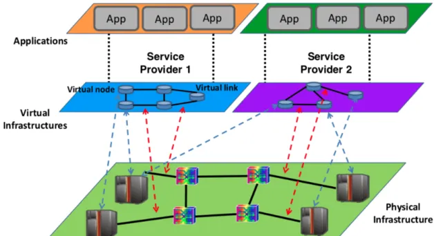
To sum up the concepts we have introduces by far:
• SDN provides an efficient way to configure connectivity services using for
example OpenFlow proposed by the ONF to connect to the physical network (in our case, optical network), making this independent of the other node.
• Applications can connect to the SDN controller using specialized, modular and
open Northbound APIs.
• OpenDaylight controller is a well known SDN controller, deeply extended in
support of optical technologies
• VDC is a form of Infraestructure as a Service (IaaS) where a tenant asks for an
infrastructure composed by VMs, interconnected through a virtual network. However, SDN technology is not sufficient to achieve an optimization of the network resources, as there are some challenges we need to face. For example, the presence of more than one data plane, the coordination of the network resources provision or the
presence of more than one SDN-controlled infrastructure. Because of all this reasons, there is a need of an orchestration layer.
The orchestration layer provides functionality such as coordinated service provisioning according to the status of the physical infrastructure and the requests coming form external users. OpenStack is an example of it, as it provides: VDC dashboard configuration, VM configuration, IP network configuration and stack configuration. In the following section, we will talk in a deeply way about the OpenStack orchestrator, but until now, this picture summaries our scenario:
3.
Our scenario
3.1. Tools needed
Before going deep in presenting our scenario, we need to explain some tools we are going to use: the SDN controller and the orchestrator.
3.1.1. OpenDaylight: the SDN controller
OpenDaylight is an open project written in Java organized by The Linux Foundation in 2013. Its objective is to accelerate the adoption of SDN networks and create a solid base to network virtual functions (NFV). The members of this project did it with the main goal to be a open platform so it can be used by different companies, avoiding the limitation of the proprietary systems and reducing the developments costs.
OpenDaylight does not have a single company. It operates through an open and active community in which anyone can join. The only requisite is to contribute on it, offering help on the development field, marketing or project management. Cisco, IBM or Microsoft are some of the members of the project.
Hydrogen was the first version of the project. It was launched in 2014 and it consisted in a simple functionality SDN controller, overlay networks, plug-ins protocols and improvements in the communication devices. After it, Helium version was launched, making OpenDaylight very popular between developers and operators.
The main advantage of this controller is that removes the adoption barriers due to the fact that there are some organizations that don’t want to get attached to a determined seller or manufacturer. With this solution, the companies could choose different technologies of different sellers, making them inter-operable.
3.1.2. OpenStack: the orchestrator
The OpenStack project is a cloud computing platform created around 7 years ago, being nowadays one of the most successful tools when implementing a private or public cloud providing an easy IaaS solution to implement.
Similar than in OpenDaylight, OpenStack is not owned by any company. It’s a foundation called OpenStack Foundation on which different members can participate to it.
As we have said, OpenStack provides an IaaS solution using interrelated services. This cloud platform tool is quite well-known due to its easy-going APIs and its modularity. Each of these modules are implemented using Python and are in charge of a specific service:
• Horizon: dashboard
• Nova: virtual machines configuration
• Cinder: block storage
• Keystone: authentication and authorization
• Swift: object storage
• Glance: images configuration
• Neutron: SDN management (networks)
A typical example of functionality could be the following: first of all the user is authenticated in Keystone, so he/she obtains a session token that will let perform the rest of the actions without having to authenticate again. Then, the user asks Glance the available images to use. After selecting one and specifying the instance characteristics (flavours), the user asks Nova to start a new instance. Finally, the Neutron service is in charge of the virtual network configuration for it.
3.2. Orchestrated SDN-enabled OPSquare DCN
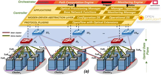
With the tools needed presented, we are ready to present our scenario. The
explanation is easy to understand looking at
Fig. 12
We can divide the scenario in 3 parts: the physical layer (Optical Data Plane), the OpenDaylight (SDN Controller) and the OpenStack (Orchestrator).
The first part is the Optical Data Plane. In this scenario, we are using OPSquare architecture, an optical DCN (Data Center Network) architecture based on fast SOA-based optical switches. There are N NxN intra-cluster (IS) switches and M NxN inter-cluster (ES) switches. Both types interconnect the inter-clusters of ToR (Top of the Racks), implemented by the FPGAs. OPSquare is also based on the Optical Flow Control (OFC) with the main goal to solve possible packet contentions at the switches. That means that the packets with high priority are directly forwarded by the switches, but the packets with low priority will be retransmitted if there is a packet collision. So, we have an scenario that using the optical data plane an the OFC protocol the data traffic an be sent between ToRs in only nanoseconds.
The second part is the SDN Controller. In the switches, there is also an OpenFlow (OF) Agent, which is in charge to collect and send information to the SDN controller. As we have seen, we are using the OpenDaylight controller, so it receives this information and decides the actions to the ToRs, with the aim to reconfigure the look-up tables of the switches or to assign packets priority depending on the applications running on each
Network Slice (NS). As we see in
Fig. 12
, there are some important blocks inside the controller:• Manager Topology: we can find the data plane layout and the physical
distribution information
• Optical Provisioning Manager: is in charge of the switches and ToRs
configuration for the Network Slices connectivity.
Finally, at the top of the structure we have the orchestrator, in our case, the OpenStack. This element has two differentiated elements:
• Monitoring Engine: in charge of collecting the data plane statistics, such as the
lost packets or the number of collisions, through the information collected by the SDN controller.
• Path Computation Engine: here is where the monitoring information is used to
compute some path algorithms, with the main goal of achieving the expected QoS. This block relies on the Optical Provisioning Manager of the SDN controller providing a new path or a flow priority service.
To sum up, we are implementing our system on a OPSquare DCN architecture with a SDN controller that controls the configurations of it and with an orchestrator that implements the management operations.
It’s important to keep in mind the goal of the project: implement the Monitoring Engine module to be able to collect the monitoring information coming from the SDN controller, so we can take some actions in the Path Computation Engine to the deployment of the service VDC affected.
3.3. The implementation
3.3.1. First approach
The first idea when starting the project was to install a combined infrastructure of the SDN controller and the orchestrator in one computer located in the IPI-ECO laboratory in TU/e (Eindhoven University of Technology). That means, a full installation of OpenDaylight and OpenStack.
The configuration of both tools was successful, and we achieved connection from OpenDaylight to the Java Agent of the switches. However, the problem we faced was with connection between OpenDaylight and OpenStack, as we found some compatibility problems due to the versions used. In the past, Universitat Politècnica de Catalunya (UPC) and Eindhoven University of Technology (TU/e) worked together in the COSIGN project, in which they achieved the integration of OpenDaylight and OpenStack by means of the VTN module of OpenDaylight. However, the version of
OpenStack that they used (Liberty) is not available anymore. And moreover, the
version of OpenDaylight used (Lithium - SR2) is a very old one. In the recent years,
post-versions have been implemented, such as Carbon, Oxygen, Fluorine or Neon, with improved features and new tools. So after this discussion, we decided that it was a must to upgrade as much as possible our infrastructure, in other words, to use one of the last versions of both tools. In that moment, we faced the problem of the compatibility versions, as when trying to make the integration of both components using the last versions, the connection between them was not successful anymore. After spending a significant amount of time on this, we decided to approach main goal of the thesis in another way.
3.3.2. Second approach
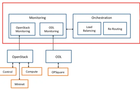
The main goal of the project remained the same: implementation of the monitoring module of OpenStack to be able to reconfigure the DCN in the Path Computation Engine block. But now the approached changed: instead of integrating OpenDaylight and OpenStack, the main idea is to deploy both components independently, so the collection of statistics will be done separately. The approach is described in the following picture:
As we can see, two modules have been included inside the Monitoring box: an OpenStack Monitoring, which will monitor the IP network and an OpenDaylight Monitoring, which will monitor the optical network.
3.3.2.1. OpenStack
In this case, OpenStack will be deployed using 3 components, as explained in
Fig. 14
,where we can see an illustration of what we’re targeting to achieve in the installation of it. Therein, there is a Management Network on top of the nodes that provides interconnection between them (192.168.0.0/24). We have also deployed an OpenStack control node and a compute node. The nova service are enabled in both nodes, which means that we have 2 instances created and running: one in the controller node and the other one in the compute node. Finally, the Mininet is intended to simulate the “Physical DC Network”, by deploying a three OVS switches topology to connect both instances. This interconnection is done through the tunnel network (10.10.10.0/24).
Fig. 14 OpenStack deployment
The instances created in the controller node and in the compute node are intended to be the TX and the RX. So the monitoring module will consists on collecting data statistics from both instances.
To develop the OpenStack Monitoring module, we will use an extra service that OpenStack provides: the Ceilometer (Telemetry Service), which will collect the traffic statistics across the various OpenStack components. In our project, we will get:
• CPU utilization
• Memory usage
• Network incoming/outcoming packets
• Network incoming/outcoming dropped packets
The version used for OpenStack is Ocata.
3.3.2.2. OpenDaylight
The installation of OpenDaylight is easy to do and to configurate: we used the Beryllium version. OpenDaylight incorporates a service called DLUX, in which we can
see in a graphical way the switches that are connected to some OF Agent. We used 3
To collect the statistics from each switch, we will use the OpenFlow plugin, which automatically collects traffic statistics from each element:
• Packets TX/RX
• Packets dropped TX/RX
• Packets rate TX/RX
• Collisions
The OpenDaylight scenario can be summarized in the following picture, where we can see that the SDN controller can send an OpenFlow message to the OF Agents of the ToR and the OPS.
3.3.2.3. Monitoring information
To develop the monitoring modules, we will use a Java application to connect to both components separately. Using REST API services, the application will get all the information in JSON format and will translate it to a graphical and structured way. This process is explained deeply in the next section of the thesis.
4.
The results
After the implementation of the scenario, we achieved the collection of statistical information on both parts:
• IP network, through OpenStack monitoring module
• OPS network, through OpenDaylight monitoring module
The installation of OpenStack and OpenDaylight was successful. For example, in
Fig.
17
we can see a screenshot of an OpenFlow packet that the SDN controller sendswhen a new node is connected. This message is also known as a FlowMod. When a OF Agent receives this type of message, it is able to configure the hardware flow tables according to the flow requirements. In the screenshot, we can also see some periodical statistics requested by the controller to the OP node.
So, let’s show in a graphical and easy way to understand the statistics obtained through both components.
On the one hand, in
Fig. 18
we can see the output of the OpenStack monitoring module. In this case, we have 2 instances (VM1 and VM2), with their respective IP addresses and their statistics about the CPU and memory usage, incoming packets,outgoing packets and so on. The CPU util is measures in % and the memory usage in
MB. The incoming/outgoing packets are measured in packets, an the incoming/outgoing packets the rate in packets/s.
On the other hand, in
Fig. 19
we can see the output of the OpenDaylight monitoringblock. In the figure we can only see 2 switches, each one of one port. The reason for this is because there were not sufficient FPGA in the TU/e laboratory, so we can connect the three OF Agent wit the FPGA. In this test, there were no collisions and no errors, as we are using a test scenario with only 2 switches. But if errors in transmission or reception occurred, it will appear in the results, so the Path Computation Engine could take some actions in the DCN.
It’s extremely important to remark the difference of packets that we can see in the previous figures. The packets monitored in the OpenStack module are electric packets, as it controls the IP network. However, the packets monitored in the OpenDaylight module are optical packets. Remember that the switches that we can see in
Fig. 18 OpenStack statistics
OpenDaylight DLUX refer to the OF Agents of the ToRs and the OPS, so this traffic is in optical format.
4.1. Path Computation Engine
Once the Monitoring module is completed and provides the necessary information to the Path Computation Engine, it’s time to work on what to do with this data. We have two sources from statistics: from the IP network and from the DCN. The main goal is to combine them and, upon some decision and benefiting from the multiple path connections among racks in the OPSquare architecture, OpenDaylight is able to reconfigure the paths to reduce packet loss maintaining the required level of QoS. Due to a lack of time, it has not ben possible to complete this module. However, some ideas have been discussed to a future work on it.
• Packets Priority: we are using the Optical Flow Control (OFC) with the aim to
solve packet contention, using packet retransmission. However, this retransmission increases the end-to-end latency. If we want to maintain the required latency , packets priority assignment is a solution. The packets with high priority will have priority when they arrive at the OPS, while the traffic with low priority will be retransmitted in case of contention. This process is shown in
Fig. 20
, where we can see two packets generated from two different ToRs. Both of them are destined to the same output of IS, so in the OPS there is packet contention. As packet 1 has a higher priority than packet 2, packet 1 will be forwarded to the output port in the IS with the aim to avoid packet loss and not to increase the end-to-end latency. This process of assigning dynamically the priority in optical packets can be done using 4 bits of the packet label, so we can define 16 different transmission priority classes.• Load Balancing: using the monitoring statistics collected from the Monitoring
Engine module, load balancing could be another option to reduce the number of
packets lost in the OPS. As exemplified in
Fig. 21
, there are 2 packets that aresent from different instances, but both are destined to the same output port in IS. As the load increases, the packet contention that is produced at that port would cause more number of lost packets from both instances. Using a good combination of the instances (VMs) statistics and of the physical switches statistics, it’s possible to reconfigure the connectivity to balance the load to the ports with less usage. What is needed to define is which threshold of packet loss guarantees the required QoS for the service.
5.
Con
clusions
In this project we have studied the use of Virtual Data Centers (VDC) in Data Center Networks (DCN). We studied the benefits of using an OPSquare architecture based on fast optical switches (SOA) and optical flow control, which features low latency and high connectivity as well as low cost and power consumption. We used OpenDaylight as a SDN controller, a software defined networking control plane to provide dynamic provisioning and reconfiguration of VDCs services. And we used OpenStack as an orchestrator to be able to trigger the operation of path computing engine, so some actions can be taken in the physical infrastructure to avoid packet loss and to decrease the end-to-end latency.
But this engine’s decision cannot be made without the Monitoring Engine module, which we have implemented during the thesis. Inside it, we demonstrate the capability to monitor the traffic that is exchanged in the OPSquare architecture, where the OF Agents and ToRs switches reside, and in the IP network, where the instances for the different VDC services are launched. This real-time data is provided to the SDN controller and therefore, to the orchestrator as statistics. The orchestrator layer has the necessary tools to perform path computation taking into account the monitoring data obtained from both networks.
As a future work, the next step should be to implement the Path Computation Engine module. In this project some ideas have been discussed, such as load balancing or priority class assignment algorithms. But it’s important to keep in mind that after a decision is taken by the orchestrator (OpenStack), then the SDN controller (OpenDaylight) is able to reconfigure the paths and data plane resources in order to increase the number of lost packets and the end-to-end latency, with always the main goal of maintaining the requested level of Quality of Service (QoS).
6.
References
[1] W.Miao, F.Yan, O.Raz, N.Calabretta. OPSquare: Assessment of a Novel Flat
Optical Data Center Network Architecture under Realistic Data Center Traffic. Article. 2016.
[2] N.Calabretta, F.Yan, W.Miao. OPSquare: towards Petabits/s Optical Data Center
Networks based on Fast WDM Cross-Connect Switches and Optical Flow Control. Article. 2017.
[3] W.Miao. Flow-controlled and SDN-enabled Optical Switching System for
High-capacity and Low-latency Flat Data Center Networks. PhD tesis. 2017.
[4] N.Calabretta, W.Miao, K. Mekonnen, K.Prifti, K.Williams. Monolithically
Integrated WDM Cross-Connect Switch for High-perfomance Optical Data Center Networks. Article. 2017.
[5] Server-world. How to use Ceilometer. [online] [Consulted on 20th April]
https://www.server-world.info/en/note?os=Ubuntu_18.04&p=openstack_rocky4&f=3
[6] OpenStack. OpenStack Docs. [online] [Consulted on 16th May]
https://docs.openstack.org/stein/
[7] F.Agraz. OpenDaylight / OpenStack Integration Tests. How-to. 2015.
[8] D.Sánchez. Gestión de data centers virtuales mediante OpenStack/SDN. Bachelor
thesis. 2016.
[9] D.Sánchez. Gestión de data centers virtuales mediante OpenStack/SDN. Bachelor
thesis. 2016.
[10] Universitat Politècnica de Catalunya. SDN/NFV and Orchestration for Optical
Transport Network: Practical use cases. Slides. 2018.
[11] A.Viñés. Network Service orchestration for SDN based Data Centers: an
OpenStack approach. Bachelor thesis. 2016.
[12] S.Subramanian, S.Voruganti. Software-Defined Networking (SDN) with
OpenStack. Book. 2016.
[13] OpenDaylight. OpenDaylight. [online] [Consulted on 2th April]
ANNEX
How-to install
OpenStack integrated
with a Mininet
Master in Telecommunications Engineering (MET)
Universitat Politècnica de Catalunya (UPC)
Eindhoven University of Technology (TU/e)
30
thMay 2019
Surname NameCONTENTS
1. SCENARIO 2 2. MININET 3 2.1. ODL CONTROLLER 3 2.2. MININET VM 4 3. OPENSTACK 63.1. CENTOS INSTALLATION ON VIRTUALBOX 6 3.2. OPENSTACK INSTALLATION 8
1.
Scenario
Our scenario will be based in the following picture.
Fig. 1 Scenario
We will have two networks:
•
Management Network: used for administration purposes, API access, public
network access and so on.
•
Data Network: connectivity between instances of OpenStack
We will have three nodes:
•
OpenStack Controller Node: the nova service is enabled.
•
OpenStack Compute Node: the nova service is enabled.
•
Mininet: this will simulate a Data Center (DC), composed by 3 SW.
In this manual, we will use VirtualBox. Before starting, we need to configure our
management network. Let’s create a NAT Network in the VirtualBox preferences. Go to
VirtualBox
!
Preferences
!
Network. Add a Network with the address
192.168.0.0/24.
2.
Minin
et
2.1. ODL Controller
In order to make the Mininet block working properly, we need a OpenDayLight
controller.
1.
Download Ubuntu and install it in a VirtualBox VM:
https://www.ubuntu.com/download/desktop
. Configure a NAT Network adapter
with the network created at the start of this manual (192.168.0.0/24).
2.
Execute the command
apt-get update
3.
Configure the etc/network/interfaces:
auto enp0s3
iface enp0s3 inet static
address 192.168.0.20
netmask 255.255.255.0
broadcast 192.168.0.255
gateway 192.168.0.1
4.
Restart the VM and check that the interface has been assigned with the @IP
provided.
5.
Install the ODL controller. In this case, we are using the version 0.3.4
Lithium-SR4. Download it using the following command:
wget
https://nexus.opendaylight.org/content/repositories/public/org/opendayli
ght/integration/distribution-karaf/0.3.4-Lithium-SR4/distribution-karaf-0.3.4-Lithium-SR4.zip
6.
Unzip the file:
unzip distribution-karaf-0.3.4-Lithium-SR4.zip
7.
Start the ODL Controller:
cd distribution-karaf-0.3.4-Lithium-SR4.zip
./bin/karaf
8.
Install the following features:
feature:install openflowplugin-all-li l2switch-all dlux-all
odl-restconf odl-mdsal-apidocs
9.
Wait until all features are installed and running. Make sure that the ODL
Controller is listening to ports 8080, 6633 and 6653.
2.2. Mininet VM
1.
Download the Mininet VM at
mininet.org/download
2.
Configure three interfaces at this VM using VirtualBox:
a.
eth0
: configured as a NAT Network Adapter in order to provide
connectivity to the Management Network to reach the ODL Controller.
b.
eth1
: configured as an Internal Network Adapter and attached to the
internal network (
intnet
) in order to allow connectivity towards the
Control Node.
c.
eth1
: configured as an Internal Network Adapter and attached to the
internal network (
intnet2
) in order to allow connectivity towards the
Compute Node.
3.
Important note. After starting the VM the interfaces recently configured will
switch places (not sure why the Mininet VM does this), in this case eth0 will be
now eth2 and eth1, eth2 will change to eth0, eth1 respectively.
a.
eth0
!
eth2
b.
eth1
!
eth0
c.
eth2
!
eth1
4.
Configure the etc/network/interfaces file, so all interfaces are enabled at boot
time.
auto eth0
auto eth1
auto eth2
iface eth2 inet static
address 192.168.0.21
netmask 255.255.255.0
broadcast 192.168.0.255
gateway 192.168.0.1
5.
Restart the VM and verify that eth2 has been assigned the @IP written as before
and that it reaches the ODL Controller.
6.
Create a new custom topology (test.py) at /
home/mininet/mininet/custom
folder. In our case, we have used the topology depicted in Fig. 2.
7.
Start Mininet using
sudo python /home/mininet/mininet/custom/test.py
3.
OpenStack
3.1. CentOS Installation on VirtualBox
1.
Download the Minimal ISO of CentOS from
https://www.centos.org/download/
2.
Install 2 VM CentOS in Virtual Box. One for the Controller Node and one for
the Compute Node.
•
Controller Node
•
RAM: 6144MB
•
Memory: 20GB
•
2 network interfaces:
o
NAT Network Adapter, using the network created before
(192.168.0.0/24)
o
Internal Network Adapter (
intnet
).
•
Compute Node
•
RAM: 4096MB
•
Memory: 10GB
•
2 network interfaces
o
NAT Network Adapter, using the network created before
(192.168.0.0/24)
o
Internal Network Adapter (
intnet2
).
3.
Run both VM. Follow the installation setup with:
•
Installation Destination: automatic partitioning selected
•
Kdump: disabled
•
Securiy police: disabled
4.
In both VM, execute
yum -y update
and reboot the machines
5.
Populate the
/etc/environment
file with below locale settings in both VM:
LANG=en_US.utf-8
LC_ALL=en_US.utf-8
6.
Stop and disable the firewalld service of both VM:
systemctl stop firewalld
systemctl disable firewalld
7.
Stop and disable the NetworkManager service of both VM:
systemctl stop NetworkManager
systemctl disable NetworkManager
8.
Enable and start network service of both VM:
systemctl enable network
systemctl start network
9.
Configure the management interface of both nodes. Edit the file in
TYPE=Ethernet
BOOTPROTO=none
DEFROUTE=yes
IPV4_FAILURE_FATAL=no
IPV6INIT=no
NAME=enp0s3
DEVICE=enp0s3
ONBOOT=yes
IPADDR=
192.168.0.11 (controller) // 192.168.0.44 (compute)
PREFIX=24
GATEWAY=192.168.0.1
DNS1=8.8.8.8
Remember to put the correct @IP in the
IPADDR
field depending which VM
you are configuring (controller or compute).
10.
Configure the tunnel traffic interface of both nodes. Edit the file in
/etc/sysconfig/network-scripts/ifcfg-enp0s8
with the following:
TYPE=Ethernet
BOOTPROTO=static
IPV4_FAILURE_FATAL=no
IPV6INIT=no
DEVICE=enp0s8
ONBOOT=yes
IPADDR=
10.10.10.2 (controller) 10.10.10.3 (compute)
NETMASK=255.255.255.0
DNS1=8.8.8.8
Remember to put the correct @IP in the
IPADDR
field depending which VM
you are configuring (controller or compute).
11.
Disable selinux from both VM in the config file
/etc/selinux/config
:
SELINUX=disabled
12.
Edit the file
/etc/sysconfig/network
with:
•
In the Controller Node:
HOSTNAME=controller.localdomain
•
In the Compute Node:
HOSTNAME=computenode1.localdomain
13.
Edit the hostname of both VM:
•
In the Controller Node:
hostname controller.localdomain
Go to
/etc/hostname
and change it for
controller.localdomain
•
In the Compute Node:
hostname computenode1.localdomain
14.
Change the file
/etc/hosts
of both VM and change it for:
•
In the Controller Node:
127.0.0.1 controller controller.localdomain localhost4 localhost4.localdomain4
::1 controller controller.localdomain localhost6 localhost6.localdomain6
•
In the Compute Node:
127.0.0.1 computenode1 computenode1.localdomain localhost4 localhost4.localdomain4 ::1 computenode1 computenode1.localdomain localhost6 localhost6.localdomain6