A Neural Network Based Response Model for High
Voltage Circuit-Breaker Testing
Wesley DOORSAMY, Pitshou BOKORO
Department of Electrical and Electronic Engineering Technology, University of Johannesburg, PO Box 17011, Doornfontein, South Africa
[email protected], [email protected]
DOI: 10.15598/aeee.v16i3.2845
Abstract. Innovative test methods for circuit break-ers are constantly sought after to reduce maintenance time and costs, yet still provide accurate assessment of this critical substation equipment. This paper pro-poses a novel method for response modelling of high voltage SF6 circuit breakers, based on artificial neural
networks, to provide a means of assessing its condition. The proposed method enables a timing response model of the circuit breaker to be developed using trip com-mand parameters. In this paper, an experimental setup is used to perform trip response testing of a three-phase 75 kV circuit breaker. The obtained data is then used to train, validate and test a Bayesian regularised artificial neural network that can predict response times of the breaker for a given set of trip command parameters.
Keywords
Circuit breaker, condition assessment, neural network, response model.
1.
Introduction
Maintenance and reliability of power system equip-ment have become increasingly important with grow-ing electricity demand and agegrow-ing of system compo-nents globally [1]. In particular, circuit breakers are critical components of a power system performing pro-tective and operational functions in the transmission and distribution categories. Therefore, effective moni-toring and assessment techniques for ensuring the reli-ability of circuit breakers are important factors in the maintenance of modern power systems [2]. Failures of high voltage SF6circuit breakers have been studied
ex-tensively, and provide a means of modelling reliability of this equipment thereby affording predictive
mainte-nance measures. While model-based methods for as-sessing circuit-breaker condition have been proposed there are many drawbacks to these methods which are discussed in this paper. A key drawback with exist-ing model-based methods is the use of historical sta-tistical data which only partially reflects the ageing process but cannot accurately determine the actual cir-cuit breaker condition [3]. Condition measurements are better suited to assessment but these are only meaning-ful when compared to an existing reference. However, these references are also based on a model or historical measurements. The variation in test conditions and operating cycles of circuit breakers can render com-parative methods inaccurate or invalid. This research proposes a method for response modelling of high volt-age circuit breakers. In this way, the response of the breaker at a past healthy state can be compared to its current state under the same test conditions. This paper presents a method for developing the response model, using an Artificial Neural Network (ANN), for a high voltage SF6 circuit breaker which can be used
to assess its condition.
2.
Circuit Breaker Condition
Assessment
There are different modes of failure for electrical equip-ment of a power system influenced by electrical, ther-mal, mechanical and ambient stresses [4]. These fac-tors, through different mechanisms, produce varying intensity and progress of ageing change to the equip-ment [5]. The same applies to circuit breakers where complete failure may be defined as causing the lack of one or more of its fundamental functions [6].
High-voltage circuit breakers are broadly classified according to insulation type. SF6is the most common
aver-age life than others, such as minimum oil and air-blast breakers [7]. The majority of failures in SF6-type
cir-cuit breakers observed in the field are due to mechan-ical problems followed by insulation problems [2] and [7].
A good indicator of circuit-breaker condition is its switching time as it has been found to be influenced by critical irregularities with the device to the extent that relationships between such anomalies and the tim-ing have been derived [8] and [9]. In [8], a reference timing is compared with the timing obtained after the breaker exhibits unusual operation. Analysis of the dif-ference between these timings provides a means of de-tecting problems with the device. Although the modal-ity employed by this method provides a useful means of assessing circuit-breaker condition, the timings used are compound and are vulnerable to variations in test conditions. More specifically, variations in the input signal/s to the device under test and environmental conditions directly influence the response time thus af-fecting the reference used by the method presented in [8]. Furthermore, the additional complexities, expense and inherent error of this methodology implore its aug-mentation in order for practical impleaug-mentation. The proposed technique builds on the timing modality for condition assessment and accounts for the variations in test conditions and compound nature of circuit breaker switching times. The modelling of circuit-breaker re-sponse timing comprising these aforementioned com-plexities is afforded through the use of ANN. ANN has become more popular in the area of power engineer-ing with applications in forecastengineer-ing [10] and [11] and condition assessment problems [12].
Modern model-based circuit-breaker condition as-sessment techniques are becoming more popular in recent times. This is because model-based methods typically can be used irrespective of the maintenance strategy - i.e. timeor condition-based [5]. The proba-bilistic methodology presented in [13] is an example of a model-based method which offers a means of quanti-fying the effect of device maintenance for circuit break-ers. This is achieved through the use of Bayesian up-dating of predetermined performance indices based on historical condition data. It should be highlighted that once again time-based responses of the circuit breaker are used as the key parameters for assessing condition thereof. Although, the Bayesian approach presented in [13] is quite useful, there are the drawbacks of the complexity involved with creating tolerance limits for the performance indices as well as obtaining suitable historical data. The end-of-life assessment of circuit breakers is of great interest to utilities and there are number of reliability model-based methods that have been proposed [1]. However, the historical data used with these types of models are prone to error
result-ing from variations in operatresult-ing cycles and conditions of circuit breakers. The presented ANN-based method overcomes these drawbacks as it does not require his-torical data and embeds model complexity in the neu-ral network. Moreover, it can be used in conjunction with reliability model-based methods. The proposed method provides a means of response modelling, there-fore a comparative assessment of multiple circuit break-ers under similar input conditions can be carried out to ensure accuracy of a particular reliability model.
3.
Methodology
3.1.
Circuit Breaker Timing Tests
There are various types of timing tests that may be performed on circuit breakers [8]. The timing test used in this work is commonly referred to as a contact speed timing test. This is a specialised test whereby a DC current signal is directly injected into the trip coil of the circuit breaker causing its main contacts to open. The injected current and the response times of the breaker are then recorded.
For this study, the contact speed timing test is per-formed on a 72.5 kV three-phase SF6 high voltage
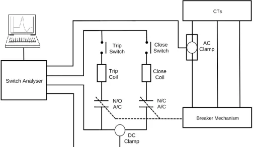
circuit breakers. A Switch Analyser (SA10) is used to perform the test in the experimental configuration shown in Fig. 1. This device consists of 12 ×2 main contact timing channels, 6 auxiliary contact channels, 3 analogue and 3 digital transducer inputs and serial communication to an external computer. The circuit breaker under test is connected such that the links to the Switch Analyser and the test circuit earth loop are established.
3.2.
Response Modelling
The timing test essentially consists of an input to the circuit-breaker system and an output or response. The three main contact times constitute the circuit breaker’s response in this case. This response can be used as a reference in condition-based assessment as previously described. However, since the response is not only dependent on the circuit breaker’s condition but also on the environmental conditions and variation in the injected signature (input), a reference timing alone will not suffice. Therefore, an actual response model of the circuit breaker is preferred. ANN is used to construct a response model that will capture the condition of the circuit breaker under test for a spe-cific input signature. This model will then be able to output the main contact response times for other in-put signatures making it possible to accurately moni-tor deviation in response times, and hence condition, of
Trip Coil N/O A/C N/C A/C Close Coil CTs Breaker Mechanism Switch Analyser Trip Switch Close Switch AC Clamp DC Clamp
Fig. 1: Experimental setup used for conducting circuit breaker timing tests.
the circuit breaker. The response model is created by
Test Parameter 1 Test Parameter 2 Response time 1 Response time 2 Response time 3 Hidden layer Input layer Output layer
Fig. 2: Architecture of ANN with Bayesian regularised back-propagation algorithm used for creation of circuit breaker response model.
training a neural network using test input signatures and recorded main contact times. For the purpose of the presented study, the neural network architecture (shown in Fig. 2) consists of 2 neurons in the input layer, 10 neurons in the hidden layer and 3 neurons in the output layer. The selection of 10 neurons in the hidden layer came about through an iterative process of seeking the best accuracy and optimal performance. It was found that, for the presented dataset, a hid-den layer with lower than 10 neurons yielded higher error, and greater than 10 neurons did not yield any improvement to the overall accuracy. The two inputs parametrise the test current signal and the three
out-put times correspond to the main contact timings of each of the three poles. The two input parameters used to characterise the input are the peak time (trI) and the peak value of the test DC current (Ip) injected into the trip coil. The contact speed timing test is repeat-edly performed with variation in the recorded injected current signatures and corresponding main contact re-sponse timings (outputs). The three rere-sponse times
trA,trB andtrC are the trip response timings for each of the three poles of the circuit breaker.
4.
Results and Analysis
4.1.
Experimental Results
Using the experimental configuration given in Fig. 1, 40 repetitions of the timing test are performed on the SF6 circuit breaker. Therefore, a set of 40 × 2
in-put parameters and 40×3 output times are obtained. Figure 3 shows three examples of DC current signals injected into the trip coil during the first three timing tests. The variations in peak times and peak values of these input currents occur in practice during testing which results in variations in response times.
4.2.
Training, Validation and Testing
The Bayesian Regularised Back-propagation (BRP) training algorithm was used rather than Levenberg-Marquardt Back-propagation (LMB) or Resilient Back-propagation (RB) algorithms. BRP uses adap-tive weight minimisation when fitting data which is particularly useful for small noisy datasets and is of-ten used in power applications such as load forecasting
Fig. 3: Samples of DC current signals as measured during re-sponse timing tests of circuit breaker showing different peak time and peak current parameters.
0 50 100 150 200 Epochs 10-1 100 101 102
Mean Squared Error (
MSE
)
Train Test Best
Fig. 4: Performance plot.
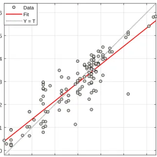
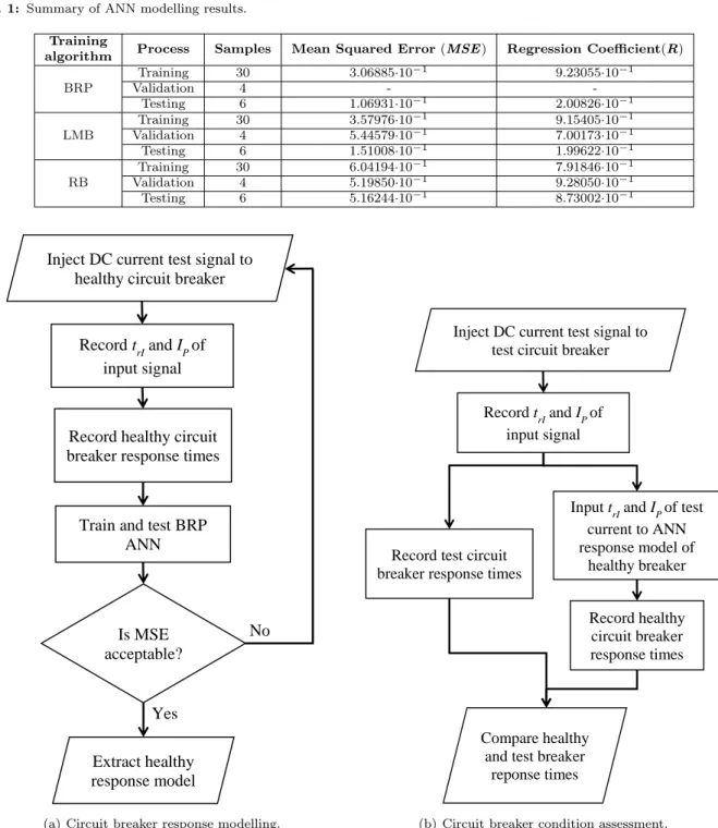
[14] and [15]. The 40 ×2 test signal parameters and 40 ×3 output times constituted the total dataset for the study. A total of 30 samples were used for train-ing, 4 for validation and 6 for testing. The best training performance yielded a Mean Squared Error (MSE) of 0.30689 obtained at epoch 69. Figure 4 shows a graph of theMSE as calculated after each epoch during test and training. The distribution of the modelling error according to each instance for the testing and train-ing processes is given in Fig. 5. The graph given in Fig. 6 shows the fitting of the data instances (train-ing, validation and test) during the construction of the response model. A summary of the testing and val-idation results for the ANN-based response model is given in Tab. 1. The results for the LMB and RB al-gorithms are also shown for the purpose of comparison with the BRP algorithm.It should be highlighted that although the MSE is not as low relative to other
ap-plications, it does serve the purpose of indicating, via the experimental results, that the proposed method has the potential for assessing the condition of high voltage circuit breakers in practice.
0 5 10 15 20 25 Instances -1.359 -1.148 -0.9373 -0.7265 -0.5157 -0.3049 -0.09413 0.1167 0.3275 0.5382 0.749 0.9598 1.171 1.381 1.592 1.803 2.014 2.225 2.435 2.646
Errors = Targets - Outputs
Training Test Zero Error
Fig. 5: Error histogram with 20 bins.
20 21 22 23 24 25 26 Target 20 21 22 23 24 25 26 Output ~= 0.79*Target + 4.7 Data Fit Y = T
Fig. 6: Linear regression result of response times fitting with coefficient R=0.88313.
4.3.
Discussion
An overview of the proposed response modelling methodology is given in Fig. 7(a), and the suggested condition assessment process is given in Fig. 7(b). In this study, the BRP training algorithm enabled good performance when using a total of 40 samples of in-put and outin-put parameters from the circuit breaker response tests. However, depending on the test
con-Tab. 1: Summary of ANN modelling results.
Training
algorithm Process Samples Mean Squared Error(MSE) Regression Coefficient(R)
BRP Training 30 3.06885·10−1 9.23055·10−1 Validation 4 - -Testing 6 1.06931·10−1 2.00826·10−1 LMB Training 30 3.57976·10−1 9.15405·10−1 Validation 4 5.44579·10−1 7.00173·10−1 Testing 6 1.51008·10−1 1.99622·10−1 RB Training 30 6.04194·10−1 7.91846·10−1 Validation 4 5.19850·10−1 9.28050·10−1 Testing 6 5.16244·10−1 8.73002·10−1
Inject DC current test signal to healthy circuit breaker
Record trI and IP of input signal
Record healthy circuit breaker response times
Extract healthy response model
Is MSE acceptable? Train and test BRP
ANN
No
Yes
(a) Circuit breaker response modelling.
Input trIand IP of test current to ANN response model of
healthy breaker Inject DC current test signal to
test circuit breaker
Record trIand IP of input signal
Record test circuit breaker response times
Record healthy circuit breaker response times
Compare healthy and test breaker
reponse times
(b) Circuit breaker condition assessment.
Fig. 7: Flow diagrams.
ditions, the MSE will differ. It is therefore recom-mended that the circuit breaker response test should be repeated during the response modelling process un-til a suitably lowMSE is acquired. Following the cre-ation of the response model, the healthy state of the circuit breaker can then be compared to its current state at the time during its life whether it is a part of condition-based or interval-based maintenance. The assessment of the circuit breaker’s condition is based on a comparative analysis of the response times of the response model (circuit breaker at healthy state) and
the current condition of the breaker. In this way, the response times can now be compared using a suitable technique to estimate how significant the difference, if any, of the circuit breaker’s response times, are to its healthy state’s responses. In this work, the model is obtained while the switch analyzer is picking up the performance of the breaker. In the presented experi-mental tests, the analyser commands the breaker to be opened in offline mode. Hence, the switching perfor-mance may be different under high voltage stress - i.e. under an in-situ test scenario. Additionally, the
inter-rupter performance may not only be affected by the amplitude of the rise time of the DC current source injected but also other characteristics arising from the electric tension. The benefit of the presented method is that response modelling can be carried out under offline or online provided that it is done consistently -i.e. if the model construction is done using offline test results then condition assessment must also be done in offline mode and vice versa.
5.
Conclusion
The condition of high voltage circuit breakers is typi-cally assessed through means of model-based methods. However, there are drawbacks to these methods such as the need for historical data. Inaccuracies thus arise from variations between operating or test conditions of the device under test and those used to build the model or as references. The presented methodology overcomes these drawbacks and enables more effective model-based condition assessment through ANN. ANN is used to construct a response model such that the cir-cuit breaker’s condition can be compared to its previ-ous state using the same input conditions. This enables the deterioration or degradation of the circuit breaker’s function to be assessed at any stage during its life.
References
[1] BOUDREAU, J. and S. POIRIER. End-of-life as-sessment of electric power equipment allowing for non-constant hazard rate - Application to circuit breakers. Electrical Power and Energy Systems. 2014, vol. 62, iss. 1, pp. 556–561. ISSN 0142-0615. DOI: 10.1016/j.ijepes.2014.05.016.
[2] ZHANG, Z., J. ZHANG, E. GOCKENBACK and H. BORSI. Life management of SF 6 cir-cuit breakers based on monitoring and diagno-sis. IEEE Electrical Insulation Magazine. 2009, vol. 25, no. 3, pp. 21–29. ISSN 0883-7554. DOI: 10.1109/MEI.2009.4976899.
[3] ZHONG, J., W. LI, R. BILLINGTON and J. YU. Incorporating a condition monitor-ing based agmonitor-ing failure model of a circuit breaker in substation reliability assessment. IEEE Transactions on Power Systems. 2015, vol. 30, no. 6, pp. 3407–3415. ISSN 0885-8950. DOI: 10.1109/TPWRS.2014.2387334.
[4] KONG, X., H. J. LIU, Y. Z. XIE, J. GUO, Q. LIU, Y. H. CHEN, S. F. WANG and X. M. SUN. High-voltage circuit-breaker insulation fault diagnosis in synthetic test based on noninva-sive switching electric-field pulses measurement.
IEEE Transactions on Power Delivery. 2016, vol. 31, no. 3, pp. 1168–1175. ISSN 0885-8977. DOI: 10.1109/TPWRD.2015.2430523.
[5] ZHANG, X. and E. GOCKENBACK. Age-dependent maintenance strategies of medium-voltage circuit-breakers and transformers. Electric Power Systems Research. 2011, vol. 81, no. 8, pp. 1709–1714. ISSN 0378-7796. DOI: 10.1016/j.epsr.2011.03.018.
[6] JANSSEN, A., D. MAKEREINIS and
C. SOLVER. International surveys on circuit-breaker reliability data for substation and system studies. IEEE Transactions on Power Delivery. 2014, vol. 29, no. 2, pp. 808–814. ISSN 0885-8977. DOI: 10.1109/TPWRD.2013.2274750.
[7] BALZER, G., D. DRESCHER, F. HEIL, P. KIRCHESCH, R. MEISTER and C. NEU-MANN. Evaluation of failure data of HV circuit-breakers for condition based maintenance. In: CI-GRE [online]. Paris: CIGRE, 2004. Available
at: http://www.transform.ru/articles/
pdf/SIGRE/a3-305.pdf.
[8] RUSEK, B., G. BALZER, M. HOLSTEIN and M. CLAESSENS. Timings of high voltage circuit-breaker. Electric Power Systems Research. 2008, vol. 78, no. 12, pp. 2011-2016. ISSN 0378-7796. DOI: 10.1016/j.epsr.2008.06.012.
[9] CHENG, T., W. GAO, W. LIU and R. LI. Eval-uation method of contact erosion for high volt-age SF6 circuit breakers using dynamic contact resistance measurement. Electric Power Systems Research. 2018, vol. 163, iss. 1, pp. 725–732. ISSN 0378-7796. DOI: 10.1016/j.epsr.2017.08.030.
[10] PEESAPATI, R., V. K. YADAV and N. KU-MAR. Assessment of temporary overvoltages during network lines re-energization. Advances in Electrical and Electronic Engineering. 2016, vol. 14, iss. 3, pp. 227–235. ISSN 1804-3119. DOI: 10.15598/aeee.v14i3.1775.
[11] BENHAMIDA, F. and R. BELHACHEM. Dy-namic constrained economic/emission dispatch scheduling using neural network. Advances in Electrical and Electronic Engineering. 2013, vol. 11, iss. 1, pp. 1–9. ISSN 1804-3119. DOI: 10.15598/aeee.v11i1.745.
[12] ZALIS, K. Solving of some Problems with On-Line Mode Measurement of Partial Discharges.
Advances in Electrical and Electronic Engineering. 2011, vol. 3, iss. 2, pp. 115–118. ISSN 1804-3119.
[13] NATTI, S. and M. KEZUNOVIC. Assessing cir-cuit breaker performance using condition-based data and Bayesian approach.Electric Power Sys-tems Research. 2011, vol. 81, no. 9, pp. 1796–1804. ISSN 0378-7796. DOI: 10.1016/j.epsr.2011.04.010.
[14] KHWAJA, A. S., X. ZHANG, A. ANPALA-GAN and B. VENKATESH. Boosted neural net-works for improved short-term electric load fore-casting. Electric Power Systems Research. 2017, vol. 143, iss. 1, pp. 431–437. ISSN 0378-7796. DOI: 10.1016/j.epsr.2016.10.067.
[15] SAINI, L. M. Peak load forecasting using Bayesian regularization, Resilient and adaptive backprop-agation learning based artificial neural net-works. Electric Power Systems Research. 2008, vol. 78, no. 7, pp. 1302–1310. ISSN 0378-7796. DOI: 10.1016/j.epsr.2007.11.003.
About Authors
Wesley DOORSAMY received the B.Sc, M.Sc. and Ph.D. Degrees in Electrical Engineering from the University of the Witwatersrand in Johannesburg, South Africa in 2008, 2013 and 2015, respectively. He is currently a senior lecturer at the University of Johannesburg and is an active member of both the Institute of Electrical and Electronics Engineers (IEEE) and South African Institute of Electrical Engineers. His research interests are in the area of intelligence in power engineering applications.
Pitshou BOKORO received M.Phil. and Ph.D. Degrees in Electrical Engineering from the University of Johannesburg, in 2011, and University of the Witwatersrand, in 2016, respectively. He is a senior lecturer at the University of Johannesburg and a mem-ber of both the Institute of Electrical and Electronics Engineers (IEEE) and South African Institute of Electrical Engineers. He works in the area of Power Systems and Surge Protection.