(will be inserted by the editor)
Graph and Model Transformation Tools for Model Migration
Empirical Results from the Transformation Tool Contest
Louis M. Rose1 (case proponent), Markus Herrmannsdoerfer2 (editor), Steffen Mazanek3 (editor), Pieter Van Gorp4 (editor), Sebastian Buchwald5, Tassilo Horn6, Elina Kalnina7, Andreas Koch8, Kevin Lano9, Bernhard Sch¨atz10, Manuel Wimmer11
1 University of York, United Kingdom, e-mail:[email protected] 2
Institut f¨ur Informatik, Technische Universit¨at M¨unchen, Germany, e-mail:[email protected]
3 e-mail:[email protected] 4
Eindhoven University of Technology, The Netherlands, e-mail:[email protected]
5 Karlsruhe Institute of Technology (KIT), Germany, e-mail:[email protected] 6
Institute for Software Technology, University Koblenz-Landau, Germany, e-mail:[email protected]
7
University of Latvia, IMCS, Latvia, e-mail:[email protected]
8
Software Engineering Research Group, Kassel University, Germany, e-mail:[email protected]
9
Kings College London, United Kingdom, e-mail:[email protected]
10 fortiss GmbH, Germany, e-mail:[email protected] 11
Vienna University of Technology, Austria, e-mail:[email protected]
Received: date / Revised version: date
Abstract We describe the results of the Transforma-tion Tool Contest 2010 workshop, in which nine graph and model transformation tools have been compared for specifying model migration. The model migration prob-lem — migration of UML activity diagrams from version 1.4 to version 2.2 — is non-trivial and practically rele-vant. The solutions have been compared with respect to several criteria: correctness, conciseness, understand-ability, appropriateness, maturity and support for exten-sions to the core migration task. We describe in detail the comparison method, and discuss the strengths and weaknesses of the solutions with a special focus on the differences between graph and model transformation for model migration. The comparison results demonstrate tool and language features that strongly impact the effi-cacy of solutions, such as support for retyping of model elements. The results are used to motivate an agenda for future model migration research (including suggestions for areas in which the tools need to be further improved).
1 Introduction
MDE introduces additional challenges for controlling and managing software evolution [48]. For example, when a metamodel evolves, instance models might no longer conform to the structures and rules defined by the meta-model. When an instance model does not conform to its
metamodel, it cannot be manipulated with metamodel-specific editors, cannot be managed with model man-agement operations and, in some cases, cannot even be loaded with modelling tools. Model migration is a devel-opment activity in which instance models are updated to re-establish conformance1 in response to metamodel evolution.
Problem. Model migration is a specialised form of mo-del transformation [72], in which the source and target metamodels are similar, but not the same. Several ap-proaches to model migration have been proposed, and each uses a particular style of model transformation. Presently, various languages are used for specifying model migration, such as a model-to-model transformation lan-guage (in the work of Cicchetti et al. [8] with the Atlas Transformation Language [39]), a language tailored to model migration (Sprinkle’s language [72]), or a general-purpose programming language (in COPE [27]). There has been little work, however, that compares the lan-guages used for performing model migration. In particu-lar, graph transformation languages have not previously been investigated in this context. Similarly, the correla-tion between language (and tool) features and the effi-cacy of a model migration approach have not yet been investigated.
1 The definition of conformance varies over model
migra-tion problems and over modelling technology, but usually at least requires that a model (graph) uses only those types de-fined by a metamodel (type graph [10]).
Contribution. In this paper, we describe the outcomes of one of the transformation cases at the 2010 edition of the Transformation Tool Contest (TTC 2010). The par-ticular case aimed at evaluating and comparing trans-formationapproaches (i.e. language/tool combinations) in the context of model migration [65]. The comparison was conducted using the criteria discussed in Section 4 (namely: correctness, conciseness, understandability, ap-propriateness, maturity, and support for extensions to the core migration task) to assess the suitability of nine approaches (Epsilon Flock, COPE, GrGen.NET, Fujaba, MOLA, PETE, ATL and Java, GReTL and UML-RSDS) for implementing a migration between a subset of the UML 1.4 and 2.2 specifications.
As discussed in Sections 8, 10 and 11, analysis of the comparison results has yielded guidance for select-ing a migration tool, motivated an agenda for future model migration research and identified classes of trans-formation approaches that are well-suited to model mi-gration. For example, the comparison results indicate that, for this specific instance of model migration, graph and model transformation tools are equally effective. Fi-nally, the practical importance of the solutions discussed in this paper has been highlighted by Tom Morris, leader of the ArgoUML2 project, who has stated that “the so-lutions of this case would be directly usable as a starting point for our UML 1.4 to UML 2.x migration facility. We have nothing available to fill this hole currently, so any contributions would be hugely valuable.”3
Outline. Section 2 discusses work relating to model migration, highlighting existing tools and comparisons. Section 3 states the goals of the comparison, and dis-cusses the formulation of three research questions that have been answered by the comparison. Section 4 presents the study object: the migration of activity diagrams from UML 1.4 to 2.2. This section also classifies model migra-tions as a special type of model transformamigra-tions, which clarifies the novelty of the comparative study. Section 5 enumerates the steps which had to be performed on the study object to be able to answer the research questions. Section 6 outlines and classifies the subjects—the trans-formation tools—that participated in the case study and presents important aspects of their solutions for the case. Section 7 presents the results of the survey in which the TTC participants had to rate all solutions along a set of criteria. Section 8 interprets these results with respect to the research questions. Section 9 lists the threats that may affect the validity of the result together with the measures taken to mitigate them. Section 10 derives a research agenda from these empirical results. Section 11 concludes the paper.
2 http://argouml.tigris.org/
3 http://is.tm.tue.nl/staff/pvgorp/events/
TTC/ttc10forum.htm(registration required)
2 Related Work
There is a large corpus of work on software evolution. In the past, studies have suggested that software evolution can account for as much as 90% of a development budget [14, 52], and there is no reason to believe that the situa-tion is different today. Although automated transforma-tion of development artefacts can be used to manage and reduce the cost of evolution [15], engineering approaches that promote the use of automated transformation— such as Model-Driven Engineering (MDE)—introduce additional challenges for managing evolution [48]. For example,model-metamodel co-evolution—in which mod-els are migrated in response to metamodel evolution—is an open research challenge in the field of MDE.
Model Migration vs. Transformation. Conceptually,
model migrations can be classified as a very special type of model transformations. Model migration involves the transformation of models without changing their mod-elling language and preserving as much as possible their structure and meaning. Model migrations are fundamen-tally different from the two transformation types that have been described most thoroughly in transformation literature [83, 49, 78]: since model migrations do not chan-ge the modelling languachan-ge, they are different from so-calledmodel translations, and since they should not chan-ge the structure of the models, they are different from so-called model rephrasings. Note that refactorings are a special case of rephrasings. Refactorings are quite dif-ferent from migrations not only at the conceptual level (they change the structure of a model) but also at the technical level: while the input and output metamodel is the same for a refactoring, this is not the case for model migrations.
In summary, model migrations are defined as trans-formations from models in one language to models in an-other version of the same language. Technically, model migrations adapt models to a new version of a language’s metamodel. Theoretically, they raise research challenges related to semantics preservation [30]. In practice, they are typically implemented with either a dedicated mi-gration language or with a transformation language.
Model Migration Approaches. Usually, the metamodel
versions share quite some similarities, as the metamodel is usually not completely changed during metamodel adap-tation [72]. Consequently, migration definitions usually contain identity rules for the unchanged metamodel parts. To reduce this boilerplate code, different approaches have been proposed [67].
Manual specification approaches—like Sprinkle’s language [72], MCL [56] and Epsilon Flock [66]—provide transformation languages that are tailored to model mi-gration and, for example, automatically copy model ele-ments.Operation-basedapproaches—like Wachsmuth’s
approach [84] and COPE [29]—provide reusable opera-tions that encapsulate recurring metamodel adaptaopera-tions and model migrations.Metamodel matching approa-ches—like Cicchetti’s approach [8] and AML [16]—au-tomatically derive a transformation definition from the difference between two metamodel versions. The existing approaches mostly use or extend existing model trans-formation languages and tools. Unfortunately, there is not much work on applying graph transformation ap-proaches to the problem of model migration.
Case Studies with Model Migration Approaches. The
existing model migration approaches have been evalu-ated in a number of case studies. The Petri net example evolution—originally proposed by Wachsmuth in [84]— has been employed as a toy example for a number of approaches [8, 16, 66, 84]. Herrmannsdoerfer et al. anal-ysed the automatability of model migration in case of two industrial metamodel evolutions from BMW Car IT [27]. The practical applicability of the operation-based tool COPE has been shown by reverse engineering the model migration for the metamodel evolution of the Pal-ladio Component Model (PCM) [29] and the evolution of all metamodels of the Graphical Modeling Framework (GMF) [31]. The matching tool AML has been evalu-ated by detecting the model migration between different versions of the Netbeans Java metamodel [16]. These case studies have only evaluated a single model migra-tion tool.
However, there has been relatively little work that seeks to compare several model migration approaches on practical cases of model migration. Rose et al. [66] compare Epsilon Flock to other model transformation and migration languages—ATL, Ecore2Ecore, COPE— using the Petri net example evolution, but they focus only on the criterion of conciseness. Rose et al. [63] de-scribe an expert evaluation of the model migration ap-proaches AML, COPE, Ecore2Ecore and Epsilon Flock using an example from the Graphical Modeling Frame-work [22], but their comparison focuses solely on tools tailored for model migration, and did not investigate general-purpose transformation languages. In particular, no existing work investigates graph transformation tools for performing model migration, and no work compares graph and model transformation tools and model mi-gration approaches. This is an area to which the work described in this paper contributes.
Comparison of Model Transformation Approaches and Tools. Existing comparisons of model and graph trans-formation focus on applications other than model migra-tion.
Czarnecki and Helsen [9] present a feature model to classify transformation languages according to their technical properties. Mens and Van Gorp [49] list differ-ent applications of transformation languages and tools and present functional and non-functional requirements
for transformation approaches. Taentzer et al. [75] com-pare the graph transformation languages AGG, TGG, VIATRA, and VMTS using the well-known object-to-relational transformation example. Grønmo et al. [23] compare the transformation languages CGT, AGG, and ATL using a complex refactoring example. Varr´o et al. [82] propose a method for comparing the performance of model and graph transformation languages. These comparisons are used here to derive criteria for the comparison of model migration approaches. Specifically, the criteria of correctness and conciseness are inspired by the work of Taentzer et al. [75] and Grønmo et al. [23].
Earlier editions of the Transformation Tool Contest (TTC) have also resulted in the publication of tool com-parisons. Varro et al. [81] present the results of the AGTIVE 2007 Tool Contest in which the participants had to specify a transformation from UML activity dia-grams to formal CSP processes for verification purposes. In this edition, 11 graph transformation tools partici-pated: Tiger, TGG, PROGRESS, GrGen.NET, GReAT, VTMS, USE, MoTMoT, GrTP, MOMENT2-GT, and XL. Extended discussions of individual solutions to that case have been published as separate papers, without de-tailed comparisons [1, 54]. There also has been a special section on the 2008 edition of the contest: P´erez et al. [59] as well as Rensink and Van Gorp [62] introduce the different cases, the execution of the contest and its re-sults: program refactoring, simulation of ant populations with a focus on performance, a realistic transformation from BPMN to BPEL models, and a live contest case on the domain of conference scheduling. There are separate publications for the different graph transformation tools that have been applied to the cases: MoTMoT [55], VI-ATRA2 [36], GReAT [50], EMF Tiger [3], GrGen.NET [37], Kermeta [53], and Fujaba [17]. The earlier editions have helped to improve the execution of the TTC.
There also have been publications that propose tech-niques to improve contests that compare transforma-tion tools. Van Gorp and Eshuis compared two solu-tions for transforming process models [79]: a solution implemented in Java and a solution implemented in Gr-Gen.NET. To effectively compare the two solutions, they propose a four-level framework. This framework is based on the assumption that the influence on criteria can only be attributed to language and tool features that have been used in the solutions. We follow this advice and thus only classify the features used in the solutions in Section 6. Moreover, we apply the framework by separat-ing language-related criteria from tool-related ones and we analyse which properties of a solution could in fact be due to language- and tool-independent design patterns. Finally, we apply the framework by analysing whether or not incompletenesses and errors in solutions are just a matter of incomplete work by the solution builders.
Van Amstel et al. investigate the automatic assess-ment of transformation quality by means of specialised metrics and associated tools [76, 77]. This is promising
work, but unfortunately the required tools are not yet available for application on the scale of our study.
3 Study Goal
The aim of TTC is to compare the expressiveness, usabil-ity and performance of graph and model transformation tools via a number of selected case studies. Participants apply their favourite graph or model transformation tool to one of the proposed cases, and the solutions are com-pared and evaluated. To contextualise the comparison described in this article, we have synthesised the follow-ing research questions from the more general aims of the contest4:
RQ1.What are the pros and cons of the different trans-formation tools considering model migration? By com-paring the solutions, we are able to identify the pros and cons of the different tools concerning the model mi-gration case. This research question is aimed at aiding prospective users of transformation languages and tools in selecting the right technology for model migration.
RQ2. Which classes of transformation tools are espe-cially well-suited for realising a model migration? By clustering solution features, we can analyse across lan-guages and tools which combinations of features have proven successful for solving the case. This research ques-tion is aimed at aiding language and transformaques-tion tool developers in improving their technology for model mi-gration.
RQ3. How do graph transformation tools compare to
model transformation (and migration) tools in a model migration scenario? This research question aims at ana-lysing whether there are any differences between graph transformation tools and model transformation (and mi-gration) tools. At the same time, we want to stimulate a more general discussion about graph vs. model transfor-mation and derive a research agenda that aims to com-bine the strengths of all approaches.
4 Study Object
For the comparative study presented in this paper, sev-eral examples of model migration were considered by the case submitters. The metamodels defined in the Gra-phical Modeling Framework [22] and UML [58] were considered carefully, since they have undergone several significant revisions of industrial relevance. The migra-tion of activity diagrams between versions 1.4 and 2.2 of the UML specification was selected for three reasons: (1) UML arguably is the most well-known modelling
4 cf.http://planet-mde.org/ttc2010/index.php?
option=com_content&id=101
language today, and hence it is likely to be familiar to participants of the contest (i.e. the study). (2) Existing UML tools have a need for migrating between differ-ent versions of the UML specification, as evidenced by Morris’s statements (cf. Section 1). (3) The migration of activity diagrams between versions 1.4 and 2.2 of the UML specification is non-trivial: the evolution involved changes to the underlying semantic model of activity di-agrams. In UML 1, activities were defined as a special case of state machines, while in UML 2, they are defined atop a variant of coloured Petri nets [70].
The remainder of this section briefly introduces UML activity diagrams, outlines the way in which activity dia-grams have evolved between the versions 1.4 and 2.2 of the UML specification, and describes the criteria used to compare the tools and languages applied to migrate an activity diagram from UML 1.4 to UML 2.2.
4.1 Activity Diagrams in UML
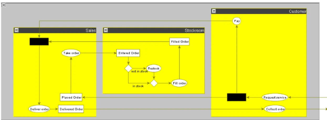
In both UML 1.4 and 2.2, activity diagrams are used for modelling workflows, such as business processes or sys-tem behaviour [58]. Fig. 1 shows an activity diagram for the sales process of an online retailer. The diagram is partitioned into three swimlanes, representing differ-ent organisational units.Activities are represented with rounded rectangles andtransitionswith directed arrows.
Forkandjoinnodes are specified using a solid black rect-angle. Decision nodes are represented with a rhombus.
Guards on transitions are specified using square brack-ets.
For example, in Fig. 1, the transition to the restock activity is guarded by the condition “[not in stock]”. Text on transitions that is not enclosed in square brack-ets represents a trigger event. In Fig. 1, the transition from theRestockactivity occurs on receipt of the asyn-chronous signal calledreceive stock. Finally, the tran-sitions between activities might involve interaction with objects. In Fig. 1, theFill Orderactivity leads to an interaction with an object calledFilled Order.
4.2 Evolution of Activity Diagrams
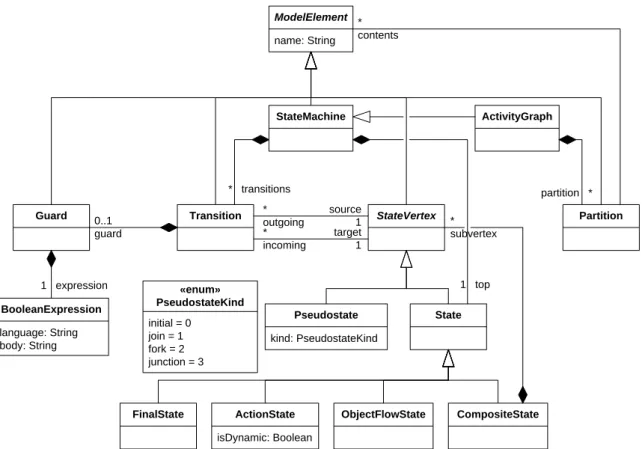
Between versions 1.4 and 2.2 of the UML specification, the metamodel for activity diagrams underwent signif-icant changes. In particular, activities are now repre-sented in Petri net concepts, such as places and transi-tions5, rather than state machine concepts, such as states and transitions. Fig. 2 highlights the main changes to the activity diagrams part of the UML metamodel between versions 1.4 and 2.2 of the UML specification. For clar-ity, Fig. 2 omits some metamodel elements that were
5 In the metamodel, these concepts are still called nodes
Customer Sales Stockroom
Request Service
Placed Order Take order Entered Order
Restock Fill order Deliver order Filled Order Delivered Order Collect order Pay [in stock] [not in stock] receive stock
Fig. 1 Example of an activity diagram based on [57]. This diagram conforms to the concrete syntax defined for activity diagrams in both the UML 1.4 and the UML 2.2 specifications.
not affected by the changes made in the UML 2.2 speci-fication. The subfigures show classes that correspond to each other in roughly the same positions.
To migrate an activity diagram from UML 1.4 to UML 2.2 (Fig. 2), the following metamodel changes must be addressed:
– ActivityGraphs are now represented as Activi-tys. Thetopandtransitionreferences are now represented using thenodesandedgesreferences. – Partitions are now represented as Activity-Partitions. The contentsreference is now rep-resented using thenodesandedgesreferences. – ActionStates are now represented as
OpaqueAc-tions.
– Pseudostates are now represented as a subtype of ActivityNode, such as InitialNode or Fork-Node.
– Transitions are now represented asObjectFlows orControlFlows.
– Guards are now represented as OpaqueExpressi-ons.
Note that the changes above refer only to abstract syntax, and do not mandate changes to the concrete syntax. This is because no changes were made to the concrete syntax of activity diagrams between UML 1.4 and UML 2.2 [73].
To facilitate the comparison of model migration so-lutions (Section 6), the activity diagram shown in Fig. 1 was migrated by hand to conform to the UML 2.2 spec-ification. The migrated model was checked by a UML
expert, and used as a reference by solution developers. Solutions were assessed according to the criteria in Ta-ble 1.
Note that this study does not question whether or not generic graph and model transformation approaches are sufficiently expressive for the manual specification of the migration from UML 1.4 and 2.2: Habel and Plumb have demonstrated that three very basic language fea-tures are sufficient for computational completeness [24]. The vast majority of graph and model transformation languages provide these features. Therefore, this com-parative study focuses on criteria such as conciseness and understandability rather than expressiveness. Even if operation-based approaches or approaches based on metamodel matching would turn out to be superior to approaches for the manual specification of migrations, it remains interesting to learn which of the general model and graph transformation approaches perform best in a migration context: the existing specialised approaches mostly use or extend existing model transformation lan-guages and tools and therefore it is interesting to anal-yse which generic approach would be the best basis for building migration-specific extensions. By involving an operation-based approach in this comparative study, we want to learn (1) whether it makes sense to extend generic approaches with a migration-specific library of opera-tions and (2) which generic approach provides the best basis if such an extension makes sense.
name: String
ModelElement
Partition
Guard Transition StateVertex
language: String body: String BooleanExpression ActivityGraph StateMachine State kind: PseudostateKind Pseudostate CompositeState FinalState isDynamic: Boolean ActionState ObjectFlowState initial = 0 join = 1 fork = 2 junction = 3 «enum» PseudostateKind partition * 1 expression * transitions 1 top * subvertex 0..1 guard * contents source 1 target 1 * outgoing * incoming
(a) Metamodel for activity diagrams in UML 1.4, based on [57].
ControlFlow ObjectFlow ActivityEdge Activity ActivityPartition ActivityNode ObjectNode ForkNode InitialNode ActivityFinalNode JoinNode 0..1 guard
* edges nodes * groups *
source 1 target 1 name: String ModelElement * nodes language: String body: String OpaqueExpression OpaqueAction * edges DecisionNode * outgoing * incoming
(b) Metamodel for activity diagrams in UML 2.2, based on [58].
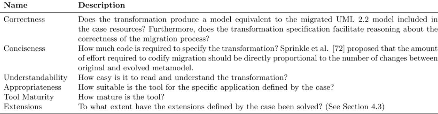
Table 1 Criteria for evaluation by participants.
Name Description
Correctness Does the transformation produce a model equivalent to the migrated UML 2.2 model included in the case resources? Furthermore, does the transformation specification facilitate reasoning about the correctness of the migration process?
Conciseness How much code is required to specify the transformation? Sprinkle et al. [72] proposed that the amount of effort required to codify migration should be directly proportional to the number of changes between original and evolved metamodel.
Understandability How easy is it to read and understand the transformation?
Appropriateness How suitable is the tool for the specific application defined by the case? Tool Maturity How mature is the tool?
Extensions To what extent have the extensions defined by the case been solved? (See Section 4.3)
4.3 Extensions
For the extensions criterion (Table 1), the solutions were compared by considering the extent to which they were applied and could be applied to address three extensions to the core task. The extensions are now discussed.
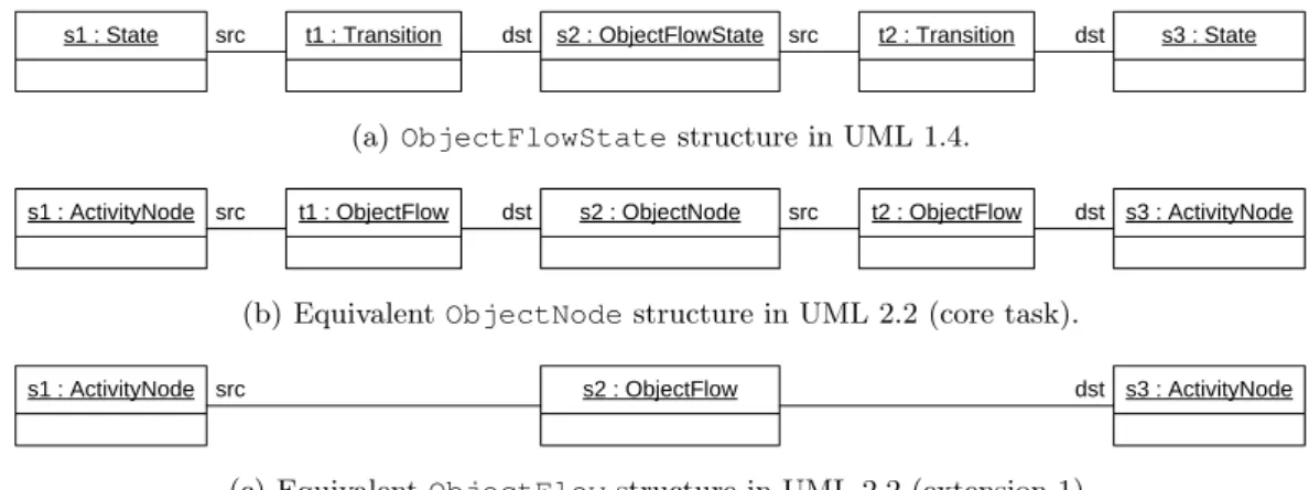
Extension 1: Alternative Object Flow State Migration Semantics. Prior to the TTC workshop, discussion on the forums6revealed an ambiguity in the UML 2.2 spec-ification indicating that the migration semantics for the ObjectFlowStateUML 1.4 concept are not clear from the UML 2.2 specification. The case was revised to in-corporate both the original semantics (core task) and an alternative semantics (extension) for migrating Ob-jectFlowStates.
In the core task, instances of ObjectFlowSta-te are migrated to instances of ObjectNode. Any in-stances ofTransitionthat had an ObjectFlowSta-teas their source or target were migrated to instances of ObjectFlow. Fig. 3 shows an example application of this migration semantics. Structures such as the one shown in Fig. 3(a) are migrated to an equivalent struc-ture shown in Fig. 3(b). TheTransitions,t1andt2, are migrated to instances ofObjectFlow. Likewise, the instance of ObjectFlowState, s2, is migrated to an instance of ObjectNode.
This extensionconsidered an alternative migration semantics for ObjectFlowState. For this extension, instances of ObjectFlowState (and any connected Transitions) were migrated to instances of Object-Flow, as shown in Fig. 3(c), in which the UML 2.2 Ob-jectFlow,f1, replacest1,t2ands2.
Extension 2: Concrete Syntax. The second extension re-lates to the appearance of activity diagrams. The UML specifications provide no formally defined metamodel for the concrete syntax of UML diagrams. However, some
6 http://planet-research20.org/ttc2010/
index.php?option=com_community&view= groups&task=viewgroup&groupid=4&Itemid=150 (registration required)
UML tools store diagrammatic information in a struc-tured manner using XML or a modelling tool. For exam-ple, the Eclipse UML 2 tools7 store diagrams as GMF [22] diagram models.
Between versions of 1.4 and 2.2 of the UML specifi-cation, there were no changes to the concrete syntax of activity diagrams [73] and hence this extension relates to migration in response to adaptive evolution (making a system compatible with a change to platforms or tech-nologies that underpin its implementation) [71, ch. 21]. To this end, submissions were invited to explore the fea-sibility of migrating the concrete syntax of the activity diagram shown in Fig. 1 to the concrete syntax in their chosen UML 2 tool. To facilitate this, the case resources included an ArgoUML project8 containing the activity diagram shown in Fig. 1.
Extension 3: XMI. The UML specifications [57, 58] in-dicate that UML models should be stored using XMI. However, because XMI has evolved at the same time as UML, UML 1.4 tools most likely produce XMI of a dif-ferent version to UML 2.2 tools. For instance, ArgoUML produces XMI 1.2 for UML 1.4 models, while the Eclipse UML2 tools produce XMI 2.1 for UML 2.2.
As an extension to the core task, submissions were invited to consider how to migrate a UML 1.4 model represented in XMI 1.2 to a UML 2.2 model represented in XMI 2.1. To facilitate this, the UML 1.4 model shown in Fig. 1 was made available in XMI 1.2 as part of the case resources9. This extension was more technical in nature than the other extensions, and was included to assess the way in which solutions could be applied for model migration in realistic scenarios.
4.4 Summary
The study object is a model migration for one of the diagram types defined in UML, activity diagrams. The
7 http://www.eclipse.org/modeling/mdt/ ?project=uml2tools 8 http://argouml.tigris.org/ 9 http://www-users.cs.york.ac.uk/˜louis/ttc/
s1 : State src t1 : Transition dst s2 : ObjectFlowState src t2 : Transition dst s3 : State
(a)ObjectFlowStatestructure in UML 1.4.
s1 : ActivityNode src t1 : ObjectFlow dst s2 : ObjectNode src t2 : ObjectFlow dst s3 : ActivityNode
(b) EquivalentObjectNodestructure in UML 2.2 (core task).
s1 : ActivityNode src s2 : ObjectFlow dst s3 : ActivityNode
(c) EquivalentObjectFlowstructure in UML 2.2 (extension 1).
Fig. 3 ObjectFlowStatemigration semantics.
abstract syntax of activity diagrams underwent signifi-cant changes between versions 1.4 and 2.2. of the UML specification, which changed the underlying semantics. Although the appearance (i.e. concrete syntax) of a UML activity diagram did not change between UML 1.4 and UML 2.2. (see Fig. 1), the way in which activities are modelled (i.e. abstract syntax) changed significantly (see Fig. 2).
5 Study Execution
The organisers of the contest devised the following steps to carry out the contest:
1. Submission of solution: Potential participants sub-mitted solutions for the migration case to the con-test. A valid submission consists of an installation in a remote virtual machine to make the solution re-producible, an accompanying document of no more than 5 pages which describes the solution, and an appendix with the full listing of the solution. The so-lution descriptions typically focus on the strengths of the submitted solution, but participants were en-couraged to fairly refer to disadvantages too. The participants could also discuss the case in a forum that was set up by the organisers.
2. Review of solution:The submitted solutions were re-viewed by experts in the domain of graph and model transformation to evaluate them with respect to va-lidity for the contest. As a result, a number of sub-mitted solutions were accepted for the contest. 3. Peer review: Workshop participants were invited to
investigate the solutions of other participants ahead of the workshop. The virtual machines as well as the solution descriptions were made available a month before the workshop, so participants could prepare for an informed judgement. Opponents (discussed in step 5) were assigned at this point.
4. Presentation of solution: The participants presented their solution at the workshop in front of all other
participants. The presentation was restricted to 10 minutes. During their presentation, the participants were given the freedom to point to these aspects that they considered most relevant for winning the con-test. The other participants of the contest could use the installation in the remote virtual machine to play with the solution and tool.
5. Presentation of opponents: To compensate for the threat that some attendees had not investigated all solutions before the workshops, each submission nee-ded to have two opponents that critically analysed the solution before the workshop. Both opponents presented the found issues and open questions to-gether in a 5 minute slot.
6. Evaluation of solution: All the contest participants were requested to fill out an evaluation sheet for each solution in parallel to the presentation. The evalua-tion sheet considered the criteria presented in Ta-ble 1 and required participants to score each solution with respect to each criterion. Based on the obtained points, the organisers awarded the best solutions for each case.
7. Statistical analysis: The organisers and case submit-ters analysed the survey outcomes statistically based on a relevant subset of the transformation compari-son criteria that are described in literature.
8. Reflection:Based on the combined results of the work-shop evaluations and the additional expert assess-ment, the organisers evaluated the effectiveness of these research steps and planned follow-up actions.
While steps 1 and 2 were conducted before the shop took place, steps 3 to 5 were conducted at the work-shop and steps 6 to 8 were conducted afterwards.
6 Study Subjects and their Solutions
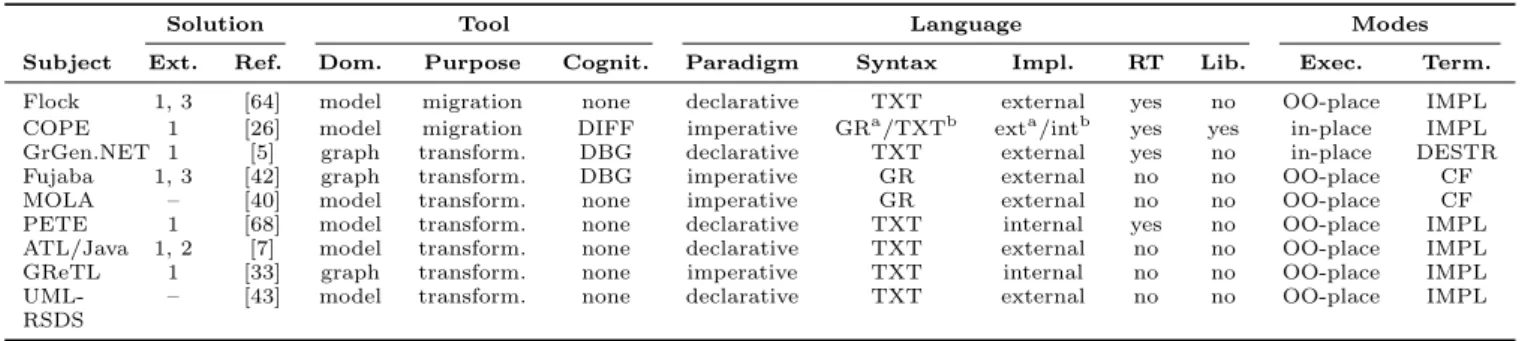
Table 2 lists the subjects that participated in the case study (in the order of the overall ranks assigned by the contest participants). For each subject, we mention the
name of the approach, classify the relevant tool and lan-guage properties and characterise the solution design.
Solution.The solution is characterised by the exten-sions it implements and areference to a more detailed solution description. This reference also provides a link to the remote installation of the tool which allows read-ers to reproduce the solution, and to apply it to addi-tional input models.
Tool.We classify a tool according to whether it orig-inates from the domain of graph or model transforma-tion. In the domain of graph transformation, models are called graphs, and metamodels are called type graphs [10]. In the case, models basically are node- and edge-typed graphs with inheritance between node types, as can be seen in Fig. 2(a) and Fig. 2(b). Due to a lot of theoretical work, graph transformation is already a very mature domain, whereas model transformation is still a comparably young discipline. In addition, we distinguish tools that are tailored tomigration and general-purpose
transformation tools. Finally, we classify tools based on their cognitive support for the development of model mi-grations. Some tools provide a visualiser of the differ-ences between input and output metamodels (DIFF in Table 2) while other tools provide rule-based debuggers with support for visualising intermediate models (DBG
in Table 2).
Language.Concerning the way the migration is de-fined, we distinguishdeclarativeand imperative langua-ges. Declarative languages focus on what needs to be transformed into what by defining a relation between the source and target models, whereasimperative languages focus on how the transformation itself needs to be per-formed by specifying the steps that are required to derive the target models from the source models [49]. In ad-dition, we distinguish languages with agraphical syntax from those with atextual syntax (resp.GR vs.TXT in Table 2). Moreover, we distinguish first-class languages from embedded languages (external vs.internal in Ta-ble 2). First-class languages have their own compiler or interpreter while languages embedded into an existing host language use the constructs provided by that host. Some languages support theretyping of model elements (RT in Table 2). Finally, some languages provide a com-prehensive library of reusable migration operations (Lib.
in Table 2) which can reduce the specification effort for solving individual case studies significantly.
Modes.Finally, we consider the execution mode ( in-place vs.out-of-place) as well as the termination mode. Forin-placetransformations the target is the same model or graph, forout-of-placetransformations the target is a new model or graph [49]. Note that various transforma-tion approaches support in-place as well as out-of-place transformation designs. Similarly, some languages sup-port multiple approaches to transformation termination. For example, languages supporting explicit control flows for scheduling rules (CF in Table 2) typically also sup-port the step-wise destruction of the input graph (
DE-STR in Table 2) for controlling rule termination [81]. However, some languages provide a single rule schedul-ing algorithm, meanschedul-ing that schedulschedul-ing – and hence ter-mination – is specified implicitly (IMPLin Table 2).
Note that we classified the transformation language features used in the solution and not all language fea-tures, since unused features do not contribute to the quality of a solution. In the following, we provide for each subject a short solution description as well as the opponent statements that were presented at the work-shop.
The following subsections give the reader a brief sum-mary of the solution descriptions, presentations and op-ponent statements in order to make the complete pro-cess as transparent as possible. Note that this leads to some unbalance in the solution descriptions but this is compensated by a subsequent section. Moreover, each solution description covers at least (1) a transformation definition fragment showing the mapping ofaction state
nodes, (2) a discussion of how this fragment is embed-ded in the overall transformation definition, and (3) a description of the most interesting tool feature. Note that Table 2 contains additional classification criteria, as explained above.
6.1 Epsilon Flock
Epsilon Flock (subsequently referred to as Flock) [66] is a model transformation language tailored for model migration. With respect to the classification in Table 2, Flock is a declarative, textual and external language and its transformations are executed out-of-place and termi-nation is implicit.
While transformation languages typically either cre-ate models afresh or updcre-ate models in-place, Flock uses an alternative strategy, which is tailored for model mi-gration and termed conservative copy. In conservative copy, model elements that conform to both the source and target metamodel are automatically copied from the source to the migrated model. Moreover, any model ele-ments that do not conform to the target metamodel are not copied.
Compared to Sprinkle’s language [72] and MCL [56] which provide similar copying strategies for migration, conservative copy is extensible (i.e. facilitates variation in conformance constraints to support, for example, mi-gration between differing modelling technologies) and
finer-grained (i.e. applies to feature values as well as model elements).
Migration ofActionStates. When executed, a Flock
migration strategy first invokes conservative copy and then invokes any user-defined rules (namely: retypings, deletions or migrate blocks). User-defined rules are used to guide and customise the conservative copy. For ex-ample, Listing 1 shows a user-defined rule (for the UML
Table 2 Overview of the study subjects.
Solution Tool Language Modes
Subject Ext. Ref. Dom. Purpose Cognit. Paradigm Syntax Impl. RT Lib. Exec. Term.
Flock 1, 3 [64] model migration none declarative TXT external yes no OO-place IMPL COPE 1 [26] model migration DIFF imperative GRa/TXTb exta/intb yes yes in-place IMPL
GrGen.NET 1 [5] graph transform. DBG declarative TXT external yes no in-place DESTR Fujaba 1, 3 [42] graph transform. DBG imperative GR external no no OO-place CF MOLA – [40] model transform. none imperative GR external no no OO-place CF PETE 1 [68] model transform. none declarative TXT internal yes no OO-place IMPL ATL/Java 1, 2 [7] model transform. none declarative TXT external no no OO-place IMPL GReTL 1 [33] graph transform. none imperative TXT internal no no OO-place IMPL
UML-RSDS
– [43] model transform. none declarative TXT external no no OO-place IMPL
ahistory model bmigration language
activity diagram migration case) that instructs conser-vative copy to create an OpaqueAction in the tar-get model for each ActionStatein the source model. Features of the sourceActionStates that conform to equivalent features inOpaqueActionare automatically copied by Flock.
Listing 1 Migrating UML 1.4ActionStates with Epsilon Flock.
1 retype ActionState to OpaqueAction
Overall Transformation. The Flock migration strategy for migrating UML 1.4 to UML 2.2 activity diagrams is written using retypings (an example of which is shown in Listing 1) and migrate blocks to change the values of features after conservative copy has been invoked. For example, the migrate block of Listing 2 is executed on every Guard in the source model and produces an OpaqueExpression(as specified by the retyping). Val-ues are copied automatically from the source to the tar-get model element when conformance would not be af-fected. For example, Guard andOpaqueExpression both define a feature,name, with the same type and mul-tiplicity. Consequently, thenameof aGuardis automat-ically copied to the correspondingOpaqueExpression before the body of the migrate block is executed. After conservative copy has copied names and other confor-mant values, the body of the migrate block is executed for eachGuard. A more detailed discussion of the struc-ture and semantics of conservative copy is available [66].
Notable Feature. The platform atop which Flock is im-plemented, Epsilon, contributes a model connectivity la-yer, EMC. The languages developed atop Epsilon ac-cess models via EMC and, hence, are decoupled from implementation details of a particular modelling tech-nology. Consequently, programs written in Flock (and the other Epsilon languages) can be executed on models represented in a range of modelling technologies: EMC currently supports EMF, MDR, Z and XML. For the UML activity diagram migration, the same Flock pro-gram could be used to migrate both the XMI 1.x (MDR) and the XMI 2.x (EMF) models. Hence, Flock imple-ments the third extension of the activity diagram case
without the need for any additional code: the user simply specifies which modelling technology will be used before launching the Flock program. EMC can be extended for use with further modelling technologies by implement-ing Epsilon’sIModelinterface and specifying an Eclipse extension.
Listing 2 Migrating UML 1.4Guards with Epsilon Flock
1 retypeGuard to OpaqueExpression
2 migrate Guard {
3 migrated.body.add(source.expression.body);
4 }
Summary. The solution presented in this section makes use of the conservative copy and model connectivity layer of Epsilon Flock. The former has been applied to min-imise the amount of duplicated (i.e. boilerplate) code by automatically copying model elements and feature val-ues that are not affected by metamodel evolution. The latter has been applied to facilitate migration between models that are specified in different formats, namely XMI 1 and XMI 2.
Opponent Statements (Cicchetti, Buchwald). Flock al-lows for concise and understandable model migration programs thanks to the conservative copying strategy. Furthermore, several metamodelling languages and model formats are supported by reusing the model connectivity layer EMC. However, how well different metamodelling languages may be supported by EMC, and subsequently, how well Flock applies for evolution scenarios of meta-models implemented with metamodelling languages be-sides Ecore has to be explored more deeply in the future. Finally, it has to be noted that a DSL approach allows for concise migration programs, but at the same time, additional effort is necessary to learn a new language for model migration instead of reusing an existing transfor-mation language.
Flock uses some implicit assumptions that allows for a concise solution: if an element of the original model and its counterpart in the migrated model have an attribute or edge with the same name, they are considered seman-tically equivalent. This assumption is true for this case study, but can be very error-prone in general. A more
conservative approach would be to consider attributes or edges as semantically equivalent if and only if they belong to a common superclass of both model elements.
6.2 COPE
COPE10 [29] is a model migration tool that records the metamodel adaptation as a sequence of operations in ahistory model. The operations can be enriched with instructions for model migration to form so-called cou-pled operations. COPE provides two kinds of coucou-pled operations – reusable and custom – which vary accord-ing to the level of automation required for model mi-gration [29]. Reuse of recurring mimi-gration specifications allows to reduce the effort associated with building a model migration [27]. COPE thus providesreusable cou-pled operations which make metamodel adaptation and model migration independent of the specific metamodel through parameters and constraints restricting the ap-plicability of the operation. Currently, COPE comes with a library of over 60 reusable coupled operations [32]. Mi-gration specifications can become so specific to a cer-tain metamodel that reuse makes no sense [27]. To ex-press these complex migrations, COPE allows the user to define acustom coupled operationby manually encod-ing a model migration for a metamodel adaptation in a Turing-complete coupled evolution language [28].
With respect to the classification in Table 2, COPE uses an imperative language and its migrating transfor-mations are executed in-place and termination is im-plicit. Reusable operations are applied with a graphical, external language and custom operations with a textual, internal language. COPE also provides cognitive support with its difference visualiser.
Migration of ActionStates. As shown in Listing 3,
the mapping of ActionStates to OpaqueActions is implemented by the reusable coupled operationRename which consistently renames a metamodel element on both the metamodel and model level. In COPE, both meta-model adaptation and meta-model migration are specified as in-place transformations, requiring only to specify the difference on both levels. In order to do so, COPE soft-ens the conformance of the model to the metamodel within a coupled operation, but ensures conformance at the boundaries of the coupled operation by means of a transaction mechanism.
Listing 3 MigratingActionStates with COPE.
1 rename(minuml1.ActionState, "OpaqueAction")
Overall Transformation. Fig. 4 shows part of the history model. TheRenameofActionStates is one of the 40 coupled operations that were applied to solve the case,
10
http://cope.in.tum.de
along with further reusable coupled operations for delet-ing features, inlindelet-ing a super class and makdelet-ing a class abstract, among others. With the exception of 1 custom coupled operation, the migration can be specified with reusable coupled operations. Therefore, the result is sim-ilar to the real-life case studies that have been performed using COPE [27, 31]. From the recorded history model, a migrator in the coupled evolution language can be gen-erated which allows to automatically migrate models.
Notable Feature. To record the history model, COPE
provides a seamless integration into the existing EMF metamodel editor, as shown in Fig. 4. The user can adapt the metamodel by applying reusable coupled operations through the operation browser. The operation browser allows to set the parameters of a reusable coupled opera-tion, and gives feedback on its applicability based on the constraints. The user needs to perform a custom coupled operation only, in case no reusable coupled operation is available for the change at hand. First, the metamodel is directly adapted in the metamodel editor, in response to which the primitive changes are recorded in the his-tory. A migration can later be attached to the sequence of metamodel changes.
If COPE was not used for adapting the metamodel like for the case, the history model needs to be recov-ered from the two metamodel versions. COPE provides tool support to reverse engineer the history model, also shown in Fig. 4. As a prerequisite, the source metamodel version is loaded directly in the metamodel editor, to-gether with its initial history. The target metamodel is displayed in the so-called convergence view that also dis-plays the difference model resulting from the comparison between the source and target metamodel. By means of the operation browser, the user can apply reusable cou-pled operations to bring the source metamodel nearer to the target metamodel. After an operation is executed on the source metamodel, the difference is automatically updated to reflect the changes.
Summary. To not lose the intention behind the meta-model adaptation, COPE records the meta-model migration together with metamodel adaptations through coupled operations. COPE provides reusable coupled operations to significantly reduce the effort required to specify a model migration. To record the coupled evolution, COPE is seamlessly integrated into the metamodel editor used to perform the metamodel adaptation. COPE provides special tool support to reverse engineer the coupled evo-lution from two metamodel versions.
Opponent Statements (Meyers, Jubeh). COPE is well
integrated into Eclipse, thus benefiting optimally from Eclipse features such as browse trees, separate views, etc., which are familiar to metamodellers. Even though almost every aspect of the metamodel changes in the
s o u rc e m e ta m o d e l ta rg e t m e ta m o d e l d if fe re n c e m o d e l h is to ry m o d e l O p e ra ti o n B ro w s e r M e ta m o d e l E d it o r Convergence View Fig. 4 User interface of COPE.
case, COPE scales very well to such revolutions, requir-ing only one custom coupled operation. This is caused by the modularity of the approach treating the model migration of different metamodel changes separate from each other. However, the migration of reusable coupled operations is fixed, requiring the specification of a cus-tom coupled operation, in case a different migration se-mantics is required. Moreover, additional effort is neces-sary to learn a new language to specify custom coupled operations.
Finally, it is hard to determine the effort for spec-ifying the model migration. While the migration only needs to be specified manually for custom coupled oper-ations, effort is also necessary to apply reusable coupled operations.
6.3 GrGen.NET
GrGen.NET11 [37] is a general purpose graph rewrite system developed at the Karlsruhe Institute of Technol-ogy (KIT). It offers a fully featured metamodel, highly expressive rules which get executed very fast [18], pro-grammed rule control, and graphical debugging. With respect to the classification in Table 2, GrGen.NET is a declarative, textual and external language and its trans-formations are executed in-place. Termination occurs fol-lowing the step-wise destruction of the input graph.
Migration ofActionStates. Listing 4 shows the trans-formation from anActionStateto anOpaqueAction, with a graph rewrite rule in GrGen.NET syntax.
Listing 4 Relabelling ofActionStatetoOpaqueAction.
1 rule transform_ActionState { 2 state:minuml1_ActionState; 3 4 modify { 11 http://www.grgen.net 5 opaque:uml_OpaqueAction<state>; 6
7 eval { opaque._name = state._name; }
8 }
9 }
Rules in GrGen.NET consist of a pattern part specifying the graph pattern to match and a nested rewrite part specifying the changes to be made. The pattern part is built up of node and edge declarations or references: Nodes are declared byn:t, wherenis an optional node identifier, and t its type. References employ the same syntax omitting the colon and type. An edge e with sourcexand targetyis declared byx -e:t-> y. The rewrite part is specified by amodifyblock nested within the rule. Usually, here one would add new graph elements or delete old ones, but for this case they should only be retyped. Retyping (i.e. relabelling) is specified with the syntaxy:t<x>which definesyto be a retyped version of the original node x, retyped to the new type t; for edges the syntax is-y:t<x>->. More information can be found in the extensive GrGen.NET user manual [4].
Overall Transformation. Fig. 5 illustrates the structure of the GrGen.NET solution [5]. Before the transforma-tion can take place, the activity diagram needs to be imported from an Ecore file describing the source meta-model and an XMI file specifying the input meta-model. After-wards the resulting activity diagram has to be exported into an XMI file that conforms to a given Ecore file de-scribing the target model.
Activity (XMI) UML 1.4 model (Ecore) Activity (GrGen) UML 1.4 model (GrGen) Activity (GrGen) UML 2.2 model (GrGen) Activity (XMI) UML 2.2 model (Ecore)
conforms to imported from transformation exported to
The import is handled by an import filter supplied with GrGen.NET generating an equivalent GrGen.NET-spe-cific type graph (i.e. a graph model file) from a given Ecore file. Afterwards the XMI adhering to the Ecore model is imported by the filter as an instance graph of the just generated equivalent GrGen.NET graph model to serve as the host graph for the following transforma-tion. The export is handled by several graph transfor-mation rules that traverse the graph hierarchically while emitting the corresponding XMI tags.
The transformation of the core task complies to the following scheme: For each node or edge type, there is one rule relabelling an element of this type, often con-taining nothing more than this relabelling, sometimes us-ing alternatives to decide between possible target types depending on the context. In the controlling sequence, a postfix star operator is used to apply each of these rules exhaustively, and an infix bar operator (denoting strict logical disjunction) is used to execute one rule after the other, as e.g. in transform_ActionState* | .... First all node types are processed, then all edge types (thus a few context dependent rules match against nodes or edges of types from the source and target model).
Notable Features. The first extension task requires to transform a node of typeObjectFlowState linked to nodes of typeTransitionto a node of type Object-Flow. This requires general graph rewriting, instead of only graph relabelling. As GrGen.NET is a graph rewrite system in the first place, this was easily handled with a single additional rule [5].
GrGen.NET does not offer a concrete syntax editor for which one could request concrete syntax migration as required by the second extension task, because the tool was originally developed for handling compiler in-termediate language graphs which do not possess a user drawn layout. However, as the ultimate goal of a con-crete syntax is a nice layout, a solution of a different kind is presented: the tool includes a highly customis-able graph viewer with automatic layout—which results in a diagram with concrete syntax very similar to that of activity diagrams, as can be seen in Fig. 6.
Summary. Employing graph relabelling rules – one rule for each node type and one rule for each edge type – we were able to give a concise and very simple solution to the model migration task. Transforming nodes inde-pendent from their incident edges provides a degree of modularity that surpasses the other solutions.
Opponent Statements (Kalnina, Rahimi). GrGen.NET
is a general purpose graph rewriting system. The given model migration case often involves renaming the types (retyping) of existing model elements—i.e. nodes and edges. Therefore the proposed solution—which mainly uses rules for retyping nodes and edges—is quite ap-propriate. Knowing the graph retyping syntax for nodes
(y:t<x>) and edges (-y:t<x>->), it is quite easy to understand the transformation rules. However, if the rea-der is not familiar with the syntax, it could be hard to guess what is done in these rules. Moreover, the organi-sation of the solution could be better; especially the de-scription of the execution order is hard to understand. Also, the transformation definition contains the concrete names of the input and output model, which restricts the flexibility in applying the definition.
Regarding conciseness, the amount of textual trans-formation code is quite small. However, the amount of code does not depend on the size of the metamodel changes but on the size of the metamodel itself, which is undesirable [72]. This is because the source and tar-get metamodel elements are located in different packages and package names are included in type names. However, in this migration case all metamodel classes were modi-fied either way.
Regarding correctness, the XMI export could not be validated in the Eclipse environment. However, the ap-proach proposed for visualisation of results is quite con-vincing and interesting.
6.4 Fujaba
The Fujaba Tool Suite12 [6] allows graphical modelling of applications using the Story Driven Modeling method-ology [86]. With respect to the classification in Table 2, Fujaba is an imperative, graphical and external language and similarly to GrGen.NET, transformations update one host graph in-place. However, the submitted Fujaba solution realises the migration using an out-of-place de-sign on a subgraph.
The submitted solution consists of a simplified UML 1.4 to UML 2.2 migration transformation which reads an XMI file as input and writes a corresponding XMI2 file as output. The transformation is completely specified using Story Driven Modeling (SDM).
Story diagrams are graph rewrite rules—embedded in activity diagrams—that allow to query and modify the application’s instance graph on a high level of abstrac-tion. Activities contain individual graph rewrite rules. A graph rewrite rule consists of a graph pattern that should be matched in the host (i.e. instance) graph. Patterns are syntactically similar to object diagrams, but also include graph/object modifications. Object or link creation is denoted by thecreate stereotype and green colour. Furthermore, names can be updated via attribute as-signment expressions.
Migration ofActionStates. The mapping of
Action-States to OpaqueActions is specified with the story diagram in Fig. 7. In the first pattern the Opaque-Action is created and its attributes are set. The
sec-12
Fig. 6 Configured-automatic layout of the resulting GrGen.NET graph.
Fig. 7 Story diagram to migrateActionStateelements.
Fig. 8 Story diagram foraddNodeToPartition.
ond pattern contains a collaboration statement ( add-NodeToPartition(sourceState, node)) to add the newOpaqueActionits partition. The correspond-ing method is also defined by a story diagram (Fig. 8).
Overall Transformation. A central migration class refers to both the input graph as UML1.4ActvityGraphand the output graph referenced by a UML 2.2 Activity. It remembers already migrated states via a StateMap-pingpointing to elements of both metamodels.
The transformation is started by searching and mi-grating the initial state. In the following, the input graph
is now traversed following all transitions between state vertices in a depth-first manner. We remember already transformed states withStateMappinginstances, so a path joining an already traversed path will terminate the transformation for that branch. Of course, this approach relies on valid input models with exactly one initial node. Each state and transition migration is specified in a story diagram comparable to Fig. 7. To adapt to changed requirements (e.g. the different transformation criteria in Extension 1) a transformation can be exchanged easily by means of object-oriented method overriding.
Notable Features. Using the Story Driven Modeling me-thodology an application can be developed with graph-ical modelling solely. As mentioned before, story dia-grams provide a programming language independent way to specify graph/object modifications. To generate exe-cutable source code for an application, a template-based (and therefore customisable) code generator is contained. The eDOBS debugger visualises the current heap of a Java program at runtime as a UML object diagram e.g. the graph elements during the transformation steps. Using the debugger, the modelled graph transformations can be applied to elements of the object diagram at run-time. Fig. 9 shows such a heap visualisation. The fig-ure also shows that the submitted migration solution provides traceability links (of type StateMapping) from source to target elements for later uses.
Opponent Statements (Sostaks, Rensink). The Fujaba
Tool Suite is a well known modelling tool. Unlike clas-sical graph rewriting approaches such as TGG or AGG, Fujaba Story Diagrams embed graph rewrite rules in UML-like activity diagrams. In such a way the execution flow of migration transformation is shown clearly at the same time having the advantage of declarative syntax for graph rewriting rules. This is the biggest advantage of Fujaba, and transformations can be understood even by non-experts.
However, some improvements of readability can still be made. For example, the submitted solution contains
Fig. 9 Object graph of two connectedActionStates after its migration.
a long explicit conditional that could have been refac-tored into a generic controller. A Story Diagram based solution to the 2007 UML2CSP contest challenge illus-trates how Java reflection can support this [21]. Read-ability decreases also by using non-domain elements (like StateHandler) in the graph rewriting rules and mix-ing them with domain-specific elements. It would be bet-ter to have a generic library instead.
The opponents have no doubt that the Fujaba Tool Suite offers great technical support for building model transformations. Besides the very useful eDOBS debug-ger, Fujaba provides very useful testing facilities. In par-ticular, JUnit tests, which are familiar to Java develop-ers, have been used for verifying the submitted solution. The specification effort is considered relatively small by the opponents, but the organisers note that it does not satisfy Sprinkle’s criterium (see Section 4). The only utility, which had to be implemented in Java, is the XMI import and export facility. Although a reflective mecha-nism has been used for XMI import, it seems that a slight adaptation of the importer is still needed for other use cases.
6.5 MOLA
MOLA13 [41] is a graphical transformation language de-veloped at the University of Latvia. It is based on tradi-tional concepts from existing transformation languages. The formal description of MOLA as well as the MOLA tool can be downloaded from the MOLA homepage. The MOLA language is conceptually very comparable to Sto-ry Diagrams, but its metamodel (abstract syntax) differs significantly to that of Story Diagrams as implemented in Fujaba. With respect to the classification in Table 2, MOLA is an imperative, graphical and external language and its transformations are executed out-of-place. Con-trol flow is specified explicitly with dedicated constructs. Rules and foreach loops are the main elements of the MOLA language. The former specify the way in which instances are to be created, deleted or changed. The lat-ter are executed for each loop variable (a special class el-ement) instance satisfying the loop-head condition (the top most MOLA rule in the loop)14.
13 http://mola.mii.lu.lv/
14 In the EMF version of MOLA a foreach loop executes
“as long as possible” (i.e. new instances that satisfy the loop
Like the Fujaba solution (Section 6.4), a traceability association was added to facilitate the transformation development and execution.
Migration ofActionStates. The transformation of an individual state is very straightforward, for example, the transformation of ActionState is shown in Fig. 10 right side. Note that along with the target element ( Opa-queAction) its mapping to the corresponding source element (the linksourceElement/targetElement) is built.
Overall Transformation. The MOLA solution of the task consists of 12 MOLA procedures. The transformation process has to be started from the top elements in the containment hierarchy, in the given case from Activi-tyGraph. All elements of a container, here Composi-teState, are transformed using a MOLA foreach loop, running over these elements (see Fig. 10, left side). It is assumed here that anActivityGraphcontains just one CompositeState. Further, the procedure State is just a “dispatcher” which finds out what kind of state is really represented by the currentStateVertexand invokes the corresponding transformation. When the nodes have been transformed, edges can be processed. Finding of end points of an edge to be created is based directly on mappings from the end points of the source edge. Fi-nally, the partitions are created and transformed nodes are attached to the corresponding partitions (again using the mappings).
Notable Feature. MOLA has an Eclipse-based graphical development environment (MOLA tool), incorporating all the required development support. A transformation in MOLA is compiled via the low-level transformation language L3 [2] into an executable Java program which can be run against a runtime repository containing the source model. For this case study, Eclipse EMF is used as such a runtime repository, but some other repositories can be used as well—e.g. JGraLab, on which the GReTL transformation language is based (see Section 6.8). To develop a solution of this case, the source and target metamodels were imported into the MOLA tool. The import facility automatically adapted the metamodels
variable, are processed by the loop) with the restriction that each instance may be processed only once.
Fig. 10 MOLA transformation example.
to the metamodelling standard required by MOLA— for example, all associations must be bidirectional. The MOLA execution environment has a built-in model im-porter and exim-porter. Therefore it was possible to execute the transformations on models produced using the origi-nal source metamodel and to produce models compliant to the target metamodel.
Summary. The MOLA solution was constructed using
foreach loops and rules to specify 12 procedures. The solution developers believe that the effort for implement-ing the MOLA solution was quite low, mainly due to the chosen straightforward development method (where each correspondence between the source and target metamodel elements was directly implemented by a MOLA pro-cedure or rule), and due to the general readability of MOLA transformations. The required infrastructure for model management within the MOLA tool was sufficient for the case.
Opponent Statements (Horn, Jubeh). The fact that
MOLA transformations are defined visually using a pro-cedural style—first transforming the root element and then transforming down the containment hierarchy— makes them easily understandable even by non-experts. The concrete syntax is close to the well-known UML ac-tivity diagrams.
MOLA supports transformations on different techni-cal spaces. One of them is the widely used de facto stan-dard EMF, and another one is JGraLab. MOLA requires that the navigability of all associations is bidirectional. For some backends like JGraLab, this requirement is met naturally. But when transforming EMF models, it might be cumbersome that all associations are made navigable in both directions.
The type dispatching in some procedures is quite ver-bose. Alternative rules are modelled in chains, and if a rule cannot be applied, the next rule connected with an ELSE flow is tested. A more concise syntax might use UML activity diagram decision nodes and attach the OCLisTypeOf() constraints as guards to the outgo-ing flows. Also, [21] may again be used as inspiration for an even more concise and flexible solution.
6.6 PETE
PETE15(Prolog EMF Transformation Eclipse plugin) is a general-purpose transformation framework. It provides mechanisms for a pure (i.e. side-effect free) declarative, rule-based approach to model transformation, accessing EMF Ecore-based models. PETE is a textual and ex-ternal language, and its transformations are executed out-of-place and termination is implicit. (Table 2).
Based on the EMF Ecore model, an instance model is described by sets of elements (each described as an entity and its attribute values) and relations (each de-scribed as a pair of entities), syntactically represented as a Prolog term. Since these elements and relations are instances of classes and associations taken from an EMF Ecore model, the structure of the Prolog term represent-ing an instance model is inferred from the structure of that model.
In PETE, a transformation is described in terms of a predicate, relating the model before to the model af-ter the transformation; e.g. in case of the migration as shown in Listing 5 by a predicatemigrateUML(UML1, UML2). To build those transformations, predicates are provided to deconstruct a model into its parts as well as to construct a model from its parts. As the struc-ture of the model is defined using only compound func-tor terms and set terms, only two forms of predicates are needed:union and (de)composition operations. The predicate union(Left,Right,All) is used to state that setAllis the union of LeftandRight. Similarly, a predicate like ModelElement(Element,Ident, Name)is used to state that an Elementof class Mo-delElementhas an identifierIdentand a nameName. Since these predicates are declarative, they can be used bidirectionally; e.g.ModelElementcan be used to de-construct a given element into its attributes as well as to construct an element from its given attributes.
Migration ofActionStates. Basically, the above men-tioned core predicates are sufficient to realise complex transformation; however, being restricted to this
low-15
![Fig. 1 Example of an activity diagram based on [57]. This diagram conforms to the concrete syntax defined for activity diagrams in both the UML 1.4 and the UML 2.2 specifications.](https://thumb-us.123doks.com/thumbv2/123dok_us/9498488.2432392/5.892.71.814.139.532/example-activity-diagram-conforms-concrete-activity-diagrams-specifications.webp)