Publicat de
Universitatea Tehnică „Gheorghe Asachi” din Iaşi Tomul LIX (LXIII), Fasc. 3, 2013
Secţia
ELECTROTEHNICĂ. ENERGETICĂ. ELECTRONICĂ
GPS AND GSM SYSTEM FOR THE DEVELOPMENT OF
CAR TRACKING APPLICATION
BY
LIVIU BRENIUC* and CRISTIAN-GYŐZŐ HABA
“Gheorghe Asachi” Technical University of Iaşi Faculty of Electrical Engineering Received: June 18, 2013
Accepted for publication: July 28, 2013
Abstract. In this paper is presented a system for tracking a vehicle using
GPS (Global Positioning System) and GSM (Global System for Mobile Communications) technologies. The main function of the system is to automatically issue of an SMS (Short Message Service) message to predefined numbers (112, police, owner) in case of an accident. The SMS will contain minimal information about the place and time of the accident and corresponding driving direction. According the European regulations, cars equipped with such systems will be mandatory starting with 2015. The system can be easily adapted for other applications, for example tracking of persons or remote control in industrial applications. The system has a minimal design, was created to verify various ideas and technical solutions and has the possibility to be extended with new functionalities to accommodate specific applications.
Key words: vehicle tracking; GPS receiver; GSM modem; mobile phone;
Bluetooth connection.
1. Introduction
The speciality literature identifies several GSM & GPS Car Tracking Systems (GGCT Systems) that are useful for car rentals, taxi driving,
*
transportation, domestic and international road transport, etc. These systems have as main purpose the remote tracking of vehicle position, status of the cars and their passengers. The GGCT Systems are made of two devices: an execution module mounted inside the supervised car and a monitoring module placed in a surveillance center or at car owner's home. The two modules communicate through the GSM using SMS. The execution module is mainly composed of: a microcontroller based system with coordinating role, a GPS receiver that will provide information on the position and the time stamp of their acquisition, a GSM modem controlled through an RS232 interface, other circuits. Monitoring module can be a mobile phone or a GSM modem connected to a PC, a smartphone connected or not to a PC. The information received from the execution module can be loaded into Google Earth or GPS Visualizer in order to see on the map the geographical position of the car.
In the GGCT System presented by Pethakar et al., (2012; 2013), useful for taxi driving, the execution module has also an RFID reader and a panic button. Before starting the car, the car driver must identify himself using the RFID system. In special cases, the driver can press the panic button, in which case the system will issue an SMS alert to the owner and the police and will block the car (execution module contains a relay connected to the car ignition system).
Ramya et al., (2012), have proposed a GGCT System useful in transportation applications. Based on the information given by GPS and speed sensors, the system provides helpful information to passengers about the arrival in the stations of the transportation vehicles. Solving a similar problem is achieved by GGCT System proposed by Mishra et al., (2012). In this case, the transport vehicles include RFID readers while RFID tags are placed in stations. Knowing the distance between stations and travel speed of vehicles, the system can provide the moments of arrival in stations.
An efficient GGCT System is proposed by Al-Khedher, (2011). In addition to the vehicle position data, the system can collect and some of the vehicle parameters through the OBD port ( On -Board Diagnostics) which also contains the CAN (Control Area Network) interface. The parameters concerned are : RPM, engine coolant temperature , vehicle speed and percent throttle. To increase the precision of the geographical position estimation the Kalman filtering is used. A compact tracking system is presented by Yakzan et al., (2008), where the system controller is implemented in an FPGA instead of using a microcontroller.
A more effective solution to data transmission through the GSM is presented by Kishore et al., (2010). In this case the SMS communication is replaced with high capacity GPRS data transfer.
Systems similar to the GGCT Systems can be used for people surveillance, usually children, elderly, disabled, kidnapped or missing persons (Idachaba, 2011; Gupta & Reddy, 2011). The system described by Gupta & Reddy, (2011) can be implemented using a smartphone equipped with GPS and
one of the Android, Symbian, Blackberry, etc., operating system.
GSM technology can be used in other fields also, such as is showed by Goel & Mishra, (2009), were a system used to control the parameters of GSM industrial systems is presented. The demonstrated systems use GPRS communication.
2. System Overview
The GGCT System proposed must meet at least the minimal requirements of European standards IP/13/534 data (European Commission, 2013) which set as mandatory the equipment of vehicles with GGCT Systems no later than 2015. These rules establish mandatory automatic triggering of an SMS (eCall) to the European emergency number 112 in case of an accident. The message must contain details of the accident for the rescue services, including the time of the incident, the accurate position of the crashed vehicle and travel direction (the travel direction is very important on motorways and in tunnels). Similarly, the system should allow the SMS triggering to be done manually.
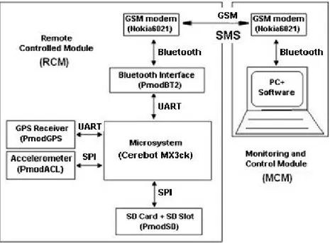
TheschematicdiagramoftheproposedGGCTSystemisshowninFig.1.
Fig. 1 – The GGCT System block diagram.
The system is made of two modules: Remote Controlled Module (RCM) mounted in the vehicle and Monitoring and Control Module (MCM) installed at the car owner's house or at a monitoring center. The modules communicate through the GSM network using SMSs.
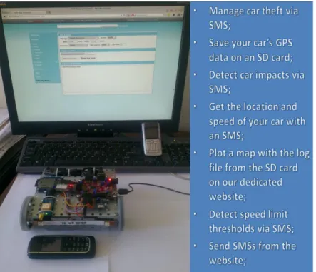
The RCM module consists of a microcontroller, GPS receiver, accelerometer, SD card, Bluetooth and GSM modem interface. The MCM module consists of a GSM modem and a PC running the software for data processing. The two component modules, operating on the test bench, are shown in Fig. 2.
Fig. 2 – The GGCT System.
The main functions of the RCM module are:
a) Recording of travel data on the SD memory card. Data consist of the route coordinates, time stamps, speed and direction of travel of the vehicle.
b) Sensing strong traffic impacts (accident) and automatically issue of a "Traffic Car Hit" type SMS to a preset phone number. The message will contain minimal information about the accident.
c) Sensing impacts in car parking and automatic issue of a "Parking Car Hit" type SMS to a preset phone number. The message will also contain minimal information about the impact.
d) Automatic issue of an "Answer (Request Data)" type SMS in response to a "Request Data" type SMS received from an MCM module that is requiring data. The "Answer (Request Data)" message will contain current information about the position and movement of the car. In order to protect the system from unauthorized data requests, the "Request Data" type SMS source is validated against a list of authorized phone numbers.
e) Manually issuing an SMS message in case of danger or not to a preset phone number (possibly 112).
The main functions of MCM module are:
a) Issue a "Request Data" type SMS message to the RCM. In order to be answered, the phone number of the MCM must be in the RCM authorized phone list.
b) Receiving messages of type "Answer (Request Data)", "Traffic Car Hit", "Parking Car Hit" and perform their processing (extraction of geographical coordinates, placing them in Google Earth to view the map position of the car) or record them in a database.
c) Process the information read from SD card and displaying it in GPS Visualizer (route map coloured based on selectable parameters: speed, distance, time).
3. The RCM Module
For the RCM module there were used several devices manufactured by Digilent Inc. The microcontroller based board used to control the system is a Cerebot MX3ck which has the following features: PIC32MX320F128H 32 bit microcontroller, 128 kB Flash memory, 16 kB RAM memory, 80 MHz max operating frequency, 42 total I/O pins, etc. The microcontroller is used to coordinate all function of RCM module and was programmed using MPIDE environment (Arduino modified for Microchip PIC32 microcontrollers). The total capacity of Flash memory used for the application was around 90 kB .
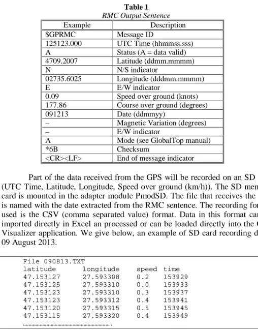
The geographical coordinates are obtained using a PmodGPS module equipped with a MediaTek GPS MT3329 receiver. The main parameters of the module are: integrated ceramic GPS antenna, 1 Hz to 10 Hz update rate, 3 m 2D accuracy without aid, ultra-high sensitivity: –165 dB.m, a 515 m/s maximum velocity and 18,000 m maximum altitude etc. The module generates a periodic signal synchronized with GPS time, 1 s in case it has a fix. This signal will be used by the microcontroller to control recordings on an SD card at multiple intervals of 1 s and only when the GPS signal is correct. The module is easy to control using an UART interface. The PmodGPS uses sentences based on the National Marine Electronics Association (NMEA) protocols for data output. You can program multiple output sentences, but in our application we have used an RMC (Recommended Minimum Characteristics) sentence output type which contains most of the GPS provided information in a concentrated form. An example of an output RMC sentence is given bellow:
$GPRMC,125123.000,A,4709.2007,N,02735.6025,E,0.09,177.86,091213,,,A*6B
Table 1 RMC Output Sentence
Example Description
$GPRMC Message ID
125123.000 UTC Time (hhmmss.sss) A Status (A = data valid) 4709.2007 Latitude (ddmm.mmmm)
N N/S indicator
02735.6025 Longitude (dddmm.mmmm)
E E/W indicator
0.09 Speed over ground (knots) 177.86 Course over ground (degrees) 091213 Date (ddmmyy)
– Magnetic Variation (degrees)
– E/W indicator
A Mode (see GlobalTop manual)
*6B Checksum
<CR><LF> End of message indicator
Part of the data received from the GPS will be recorded on an SD card (UTC Time, Latitude, Longitude, Speed over ground (km/h)). The SD memory card is mounted in the adapter module PmodSD. The file that receives the data is named with the date extracted from the RMC sentence. The recording format used is the CSV (comma separated value) format. Data in this format can be imported directly in Excel an processed or can be loaded directly into the GPS Visualizer application. We give below, an example of SD card recording dated 09 August 2013.
File 090813.TXT
latitude longitude speed time
47.153127 27.593308 0.2 153929 47.153125 27.593310 0.0 153933 47.153123 27.593310 0.3 153937 47.153123 27.593312 0.4 153941 47.153120 27.593315 0.5 153945 47.153115 27.593320 0.4 153949 ……….
For interfacing with GSM environment is necessary to use a GSM modem. The solution we have adopted takes into account cost reduction and increasing flexibility of RCM module. In this sense it was used a normal mobile phone connected to the microcontroller board using one of the available communication interfaces. The phone used was a Nokia 6021 which has an F-bus serial interface and Bluetooth wireless interface. For convenience and versatility we have chosen to use the Bluetooth interface. For this reason we used a PmodBT2 module that connects the system to the Bluetooth network.
The Bluetooth module is designed around the Roving Networks® RN-42 chip and has the following features: 2.1/2.0/1.2/1.1 compatible Bluetooth interface, a simple controlling UART interface, a wide range of modes (Slave Mode, Master Mode, Trigger Master Mode, Autoconnect Master Mode, Auto-connect DTR Mode and AutoAuto-connect Any Mode), etc. The module is controlled using its UART interface and is initialized in DUN-DTE Master or Client mode using "S~2" command.
The microcontroller board will send commands to Nokia6021 phone using the PmodBT2 module. This mobile phone supports sending the Hayes AT command set via the Bluetooth interface. For example the command "AT + GMGL = "REC UNREAD" can be used by the microcontroller board to read the unread SMS messages from the mobile phone using the PmodBT2 module.
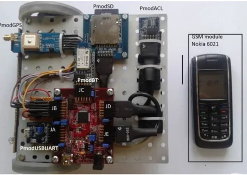
For detecting impacts on traffic or in car parking and issuing an automatic SMS, the RCM module is equipped with a PmodACL module. This module is based on a 3-axis ADXL345 accelerometer with programmable measurement range (+/–2g, +/–4g, +/–8g, +/–16g) and resolution (10 bit to 13 bit). The RCM module is shown in Fig. 3.
Fig. 3 – RCM module.
4. The MCM Module
MCM module must be able to perform the following operations: SMS issue, receive and manage SMS messages, find the point on the map based on
geographic coordinates (using Google Earth), process the information stored on the SD card and display them (using GPS Visualizer). Some of these functions can be accomplished using a smartphone connected to the Internet.
We have adopted a cheap solution that use a mobile phone (that will act as a GSM modem) connected to a PC via the Bluetooth interface. Emission and managing received messages was performed using a dedicated Web site. The data on the SD card being recorded in *. csv file can be loaded directly into Excel. The only processing that was performed was to eliminate erroneous data. Resulting filtered data can then be loaded into the GPS Visualizer.
4. Experimental Results
The system was tested in different mounting and driving conditions. Position data recorded was consistent with position data recorded using a separate GPS system. Different impact strengths were simulated and every time the result was the issue of the requested message (traffic or parking incident).
For educational purposes the RCM module has been also installed on a controlled moving platform that can be operated and tested in the small area of a university building or laboratory (see Fig. 3).
We present two different type messages received by the MCM module: a) “Traffic Car Hit” SMS message
Your car was hit in traffic: Place:
http://maps.google.com/maps?q=47.092491,27.349970&t=k&z=18
Force:9.1 Back:Side Coarse 17.25
b) “Answer (Request data)” SMS message
Answer (Request Data) Your car is here:
http://maps.google.com/maps?q=47.153120,27.593203&t=k&z=18 with
Speed of 47.5 Km/h Coarse 48,25
In both cases the SMS contains an URL (Uniform Resource Locator) link that opens Google Earth with the geographical coordinates of the incident location.
In Fig. 4 is depicted an example of the vehicle route that is traced based on data recorded on the SD card and where the route is coloured based on the vehicle speed. Using this view, we can quickly identify sectors where the vehicle was driven at high speed or the ones where the vehicle was driven at low speed.
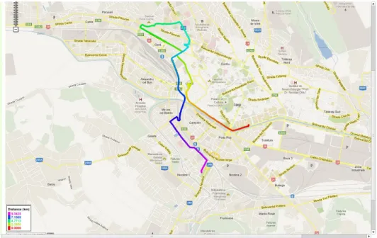
In Fig. 5 is given another example of displaying a route recorded on SD card. This time the route is viewed with GPS Visualizer with colouring based on distance. This way one can actually identify the start point and the direction of movement.
Fig. 4 – Vehicle route coloured based on vehicle speed.
Fig. 5 – Vehicle route coloured based on distance revealing start point and travel direction.
4. Conclusions
Under European regulations cars equipped with GSM warning systems in case of accident is mandatory starting with 2015. These systems must be able to issue an SMS to the number of European emergency call 112 containing details of the accident to be used by the rescue services. The details are the time of the incident, the accurate position of the crashed vehicle and the direction of travel (most important on motorways and in tunnels). Similarly, manually triggering an SMS must also be possible.
The system proposed in the present paper meets all these requirements and is done with the modules at hand in a laboratory specialized in electronics and computers. As GSM modems we used two regular phones connected via
Bluetooth interface. This choice has the following advantages : low price, the use of mobile for the purpose for which they were designed, easy manual issue of an SMS (requirement imposed by European regulations) in case of accident, possibility of changing the SMS destination number (other number than 112).
REFERENCES
Al-Khedher M.A., Hybrid GPS-GSM Localization of Automobile Tracking System. Internat. J. of Comp. Sci. & Inform. Technol. (IJCSIT), 3, 6 (2011).
Goel A., Mishra R.S., Remote Data Acquisition Using Wireless – Scada System. Internat. J. of Engng. (IJE), 3, 1 (2009).
Gupta R., Reddy B.V.R., GPS and GPRS Based Cost Effective Human Tracking System Using Mobile Phones, Wiewpoint. 2, 1, January-June 2011.
Idachaba F.E., Design of a GPS/GSM Based Tracker for the Location of Stolen Items and Kidnapped or Missing Persons in Nigeria. ARPN J. of Engng. a. Appl. Sci., 6, 10 (2011).
Kishore T.K., Vardhan T.S., Narayana N.L., Vehicle Tracking Using a Reliable Embedded Data Acquisition System with GPS and GSM. Internat. J. of Comp. Sci. a 286nd Network Security (IJCSNS), 10, 2 (2010).
Kulandaivel R., Ponmalar P., Geetha B., Saranya G., GPS and GSM Based Vehicle Information System. Internat. J. of Commun. a. Engng., 01, 1, (2012).
Mishra D., Vasal A., Tandon P., A Novel and Cost Effective Approach to Public Vehicle Tracking System. Internat. J. of UbiComp (IJU), 3, 1 (2012).
Pethakar S.S., Srivastava N., Suryawanshi S.D., GPS and GSM based Vehicle Tracing and Employee Security System. Internat. J. of Comp. Appl. (0975 – 8887), 62, 6 (2013).
Pethakar S.S., Srivastava N., Suryawanshi S.D., RFID, GPS & GSM Based Vehicle Tracing & Employee Security System. Internat. J. of Adv. Res. in Comp. Sci. a. Electron. Engng. (IJARCSEE), 1, 10 (2012).
Yaqzan A. I., Damaj I. W., Zantout R. N., GPS-Based Vehicle Tracking System-on-Chip. Proc. of the World Congr. on Engng., July 2 - 4, 2008, London, U.K., I. ** * Automated Emergency Call for Road Accidents Mandatory in Cars From 2015,
SISTEM GPS ŞI GSM DESTINAT APLICAŢIILOR DE URMĂRIRE A
AUTOVEHICOLELOR (Rezumat)
Se prezintă un sistem bazat pe tehnologiile GPS şi GSM destinat aplicaţiilor de urmărire a autovehiculelor. Utilizarea acestor sisteme este obligatorie începând cu
anul 2015, conform normativelor europene actuale. Principalele facilităţi oferite de sistem sunt: emiterea automată a unui mesaj SMS la numărul european de urgenta 112, în caz de accidentare cu precizarea detaliilor despre accident (poziţia geografică, direcţia de mers, forţa de impact etc.), obţinerea de informaţii de la autovehicul ca răspuns la un mesaj SMS trimis de la un număr prestabilit, stocarea datelor într-o
memorie locală pe toată durata deplasării, posibilitatea de a afişa rapid poziţia geografică a locului accidentului cu ajutorul aplicaţiei Google Earth, posibilitatea afişării traseului urmat de autovehicul cu ajutorul aplicaţiei GPS Visualizer, cu precizarea anumitor parametrii culeşi de pe traseu.