Interactive Video Segmentation
based on Quasi-Flat Zones
Jonathan Weber
University of StrasbourgLSIIT
Pˆole API - Bd S´ebastien Brant 67412 Illkirch CEDEX FRANCE
Email: [email protected]
S´ebastien Lef`evre
University of South BrittanyVALORIA
Campus de Tohannic - Bˆat. ENSIbs 56017 Vannes CEDEX, FRANCE Email: [email protected]
Pierre Ganc¸arski
University of StrasbourgLSIIT
Pˆole API - Bd S´ebastien Brant 67412 Illkirch CEDEX FRANCE
Email:[email protected]
Abstract—Video data is continuously increasing in personal databases and Web repositories. To exploit such data, a prior segmentation is often needed in order to get the objects-of-interest to be further processed. However, the segmentation of a given video is often not unique and indeed depends on user needs. Personalized segmentation may be achieved using interactive methods but only if their computational cost stays reasonable to enable user interactivity.
We address here the problem of interactive video segmentation and introduce a 2-step segmentation scheme: 1) offline processing to automatically extract quasi-flat zones from video data, and 2) online processing to interactively gather quasi-flat zones and build objects-of-interest. Our approach is able to deal with multiple objects, robust to errors introduced by the automatic segmentation step, and does not require to perform again the whole segmentation process each time the user provides some feedback.
Index Terms—Video analysis, Object segmentation, Interactive process, Quasi-Flat Zones, Morphological approach
I. INTRODUCTION
Following the increase of textual and then image data in per-sonal databases and Web repositories, we are currently facing the same evolution with video data. Many video processing schemes or related use cases require a prior segmentation in order to get the objects-of-interest to be further processed, e.g. video object mining [1]. However, the segmentation of a given video is often not unique and depends on user needs. While video segmentation is still an open and ill-defined problem, personalized or user-based segmentation may be achieved using for instance interactive methods. However, such methods can only ensure user interactivity if their computational cost stays reasonable, since the user will not accept to wait too long between each interaction.
In this paper, we address the problem of interactive video segmentation and introduce a new segmentation scheme, which is based on two steps: 1) offline processing to extract quasi-flat zones from video data, and 2) online processing to interactively gather quasi-flat zones and build objects-of-interest. This paper is organized as follows: we first recall some recent interactive video segmentation methods in order to underline our contribution. We then deal with a recent mor-phological segmentation tool, called segmentation into Quasi-Flat Zones (QFZ), and provide its definitions for both the
well-established image case and the more recently addressed video case [2]. The next sections are dedicated to our interactive segmentation method based on QFZ and its evaluation and comparison against existing approaches. Finally, we conclude and present some perspectives.
II. INTERACTIVEVIDEOSEGMENTATION
Interactive video segmentation means that a user is involved to guide the segmentation process. It can be easily achieved by allowing the user to change segmentation parameter settings and to see the subsequent results, but this kind of user interactivity is far from being intuitive. There are mainly two intuitive schemes for interactive video segmentation: either the user provides a visual input (i.e., she draws markers) to guide the segmentation process, or she is offered a way to correct segmentation results built from an automatic process.
Price et al. [3] propose a correction method based on automatic video segmentation obtained through graph-cut and different features computed from tiny regions returned by a watershed segmentation used as a preprocessing step. The segmentation is computed frame by frame. The user can correct the result of each frame, and its feedback is also prop-agated to the next frame following a feature weighting process within the graph-cut scheme. Flores and Lotufo [4] design a method based on the marker-based watershed involving both marker drawing and correction. The user draws markers on the first frame to guide the watershed process. The result of the watershed segmentation is then used to define new markers to be used in the next frame according to inter-frame motion. The user can correct the markers in any frame: it will result in a new segmentation of the current frame and an updating of the segmentation results of the following frames. Bai and Sapiro [5] combine markers and geodesic distance to segment a video as a 3D image. Each pixel is assigned to the closest marker according to its geodesic distance to markers, and a weighted gradient is used to compute the markers. Zhi and Ji [6] combine watershed segmentation and region merging. While the former is used as a preprocessing step, the latter relies on a seeded region growing algorithm and is applied on the region adjacency graph of the initial watershed segmenta-tion. The result can be corrected by assigning manually each
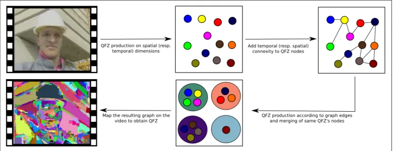
QFZ production on spatial (resp.
temporal) dimensions Add temporal (resp. spatial) connexity to QFZ nodes
QFZ production according to graph edges and merging of same QFZ's nodes Map the resulting graph on the
video to obtain QFZ
Fig. 1. Video Quasi-Flat Zones production by separated processing of spatial and temporal dimensions.
incorrect region to foreground or background.
While these methods provide good results, they suffer from some limitations: [4], [5], [6] are only able to deal with a single main object vs. its background; [3], [4], [6] are frame-based approaches, and the user is then expected to check each frame of the video sequence; [3], [6] rely on an automatic preprocessing step to provide an initial segmentation result which cannot be further corrected; finally, user correction in [4], [5] requires to perform again the whole segmentation process.
In order to overcome these limitations and to propose an efficient interactive video segmentation method, we suggest to first build a spatio-temporal oversegmentation result, and then merge the different regions according to user markers. Segmentation correction is achieved by editing the markers and performing again only the merging step and not the whole segmentation process. If irrelevant regions are found within the initial oversegmentation result, the segmentation process is locally recomputed according to user feedback. The initial oversegmentation result is made of Quasi-Flat Zones (QFZ) which have interesting frontiers and may be considered as puzzle pieces [7] to be further gathered into objects. We present this tool in the next section.
III. QUASI-FLATZONES
A. Still Image QFZ
Flat zones [8] have been studied within the field of Mathe-matical Morphology and are seen as elements with interesting properties. Indeed, a flat zone is defined as a connected set of pixels having the same value. Since object frontiers in digital images are mostly located between pixels of different values, object frontiers are expected to be included in frontiers between flat zones (apart if the image resolution is insufficient, which will not be considered here). However, flat-zones are often only a few pixels wide so the resulting partition is
an extreme oversegmentation and is hardly exploitable. Less constrained definitions have thus been proposed, leading for instance to the Quasi-Flat Zones and more precisely theα-CC (see [7] for a survey on QFZ).
The α-CC of a pixel p is defined as the connected set of pixels which can be reached through (at least) one path verifying the following condition: the difference between values of successive pixels within the path is less or equal to a given parameter α. Let us observe that flat zones are a particular case of α-CC with α = 0. But, contrary to flat zones, segmenting an image into α-CC with α > 0 may result in an undersegmentation phenomenon. If α is set too high, it will lead to a so-called chaining effect, which may even result on a single QFZ for the whole image. In order to counter this problem, several new QFZ definitions based on α-CC have been elaborated (see [7] for more details). These definitions have been subsequently unified by Soille and Grazzini [9], [10], who propose a theoretical framework called logical predicate connectivity.
In this new framework, a QFZ (noted (P1, . . . , Pn)-CC
here) is expected to satisfy all the n logical predicates Pi.
We will denote by Pi(S) the fact that a predicate Pi is
valid over a setS. Various predicates may be involved, such as the global range predicate which is true if and only if the difference between minimal and maximal pixel values within a QFZ is less or equal to a given threshold ω. The (P1, . . . , Pn)-CC thus consists in finding, for each pixel p,
the largestα-CC which satisfies all the predicates. Moreover, since the following property holds:
∀α0 ≤α, α0-CC(p)⊆α-CC(p) (1) an iterative computation scheme may be involved. Indeed, when predicates are not verified for a given value ofα, we only need to decrement α and check once again if the predicates are verified. This loop is repeated until finding the maximal
value ofαfor which all the predicates are verified: (P1, . . . , Pn)-CC(p) = _ α0-CC(p)| ∀k∈ {1, . . . , n},∀α”≤α0,∀q∈α0-CC(p), Pk(α0-CC(p)) andPk(α00-CC(q)) (2)
Some clues to define QFZ in multivariate images have also been given by Soille [7], where α is assumed to be a vector with the same value in all components. Thus α may be easily ordered through a total ordering (e.g., decrementing α= (3,3,3) gives α= (2,2,2)). Global range predicate is processed similarly, and is true only if it is verified marginally for all bands.
QFZ are well defined for still images. Their extension to video is not straightforward and implies some new segmen-tation schemes. We have already addressed this problem [2] and recall this previous work in the next section.
B. Spatio-temporal QFZ
Extending the concept of QFZ to video data may be achieved by several ways. Probably the easiest one consists in a 3D straight extension, where a spatio-temporal neigh-bourhood is considered instead of a spatial one. However, spatial and temporal dimensions are intrinsically different and results provided by such a trivial 3D approach may not be relevant. We rather consider here a 2D+t method which successively (and no more jointly) deal with the spatial and temporal dimensions. First, we compute the QFZ considering only the spatial dimension, i.e. on a frame by frame basis. QFZ are then considered as elementary units, represented within a graph structure where each QFZ or node is valued (e.g., using the QFZ mean value). The temporal dimension is then studied to connect QFZ from successive frames which have overlapping spatial coordinates. The graph structure is updated by adding edges for each connection between QFZ. Edges are also valued by the distance (e.g., euclidean distance) between their associated nodes. In this 2D+t segmentation scheme, the QFZ are defined within the graph as the largest connected components of nodes whose connecting edges have a value less or equal to α and which do not violate any predicate. This video extension of QFZ is presented in figure 1. Let us observe that we can apply this process by inverting spatial and temporal dimensions, i.e., starting by identifying QFZ using a temporal neighbourhood only, and then linking nodes by edges considering a spatial neighbourhood. Experimental results performed by the authors have demonstrated a superiority of 2D+t andt+ 2D approaches over the3D approach. Thus these oversegmentation schemes will be used further in this paper.
While our interactive segmentation scheme relies on an oversegmentation result provided by the computation of the QFZ, the oversegmentation effect should not be too important to make the subsequent merging step computationally effi-cient and to ensure user interactivity. Thus, we also apply a filtering process to reduce oversegmentation induced by the QFZ approach. In still images, QFZ filtering often consists in
keeping only QFZ having a minimal spatial area. We extend this principle to video data by considering the average spatial area of the QFZ, computed as the ratio between the spatio-temporal volume and the length of the QFZ (i.e., the ratio between the number of pixels within the QFZ and the number of successive frames where the QFZ appears). All QFZ with a average spatial area below the filtering threshold are merged with the neighbouring QFZ having the most similar mean color. Let us note that this criterion was shown to provide better results than a straight extension of 2D area to 3D volume.
IV. INTERACTIVESEGMENTATIONSCHEME As indicated in the first sections, we aim in this paper to introduce a new interactive video segmentation method able to overcome drawbacks encountered by existing works (see Sec. II). User interactivity is only possible if the segmen-tation process requires a relatively low compusegmen-tational cost. Nevertheless, building a meaningful video segmentation needs to process a huge data volume (i.e., duration × framerate
× image width × image height pixels). Thus we propose
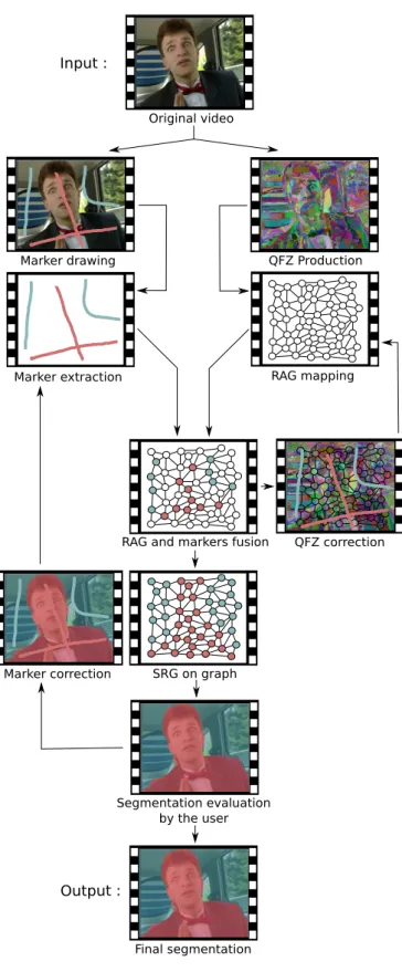
here a two-step segmentation approach, where the first step is performed offline and does not need user intervention, while the second step is online and interactive. This approach is presented in figure 2.
A. Offline Part
The offline part consists in building a first segmentation into QFZ from the whole set of pixels contained in the video sequence. QFZ are computed using the scheme presented in Sec. III. More precisely, we consider the (P1, . . . , Pn)-CC
definition with the 2D+t extension to video data. QFZ are then represented through a spatio-temporal region adjacency graph (RAG). These operations are the most computationally intensive steps of our method, and are thus performed offline (i.e., before user interactivity).
B. Online Part
The online part relies on the user to refine interactively the initial QFZ oversegmentation and build a user-based or personalized segmentation. First, the user is asked to edit and provide markers to the segmentation refinement process. To do so, she is expected to draw scribbles over both objects-of-interest and background. Each scribble is assigned to a label, and scribbles related to the same label are considered as a single marker even if they are not spatiotemporally connected. By this way, scribbles may be drawn in different frames.
Contrary to existing works, the initial segmentation (result-ing here from the offline step) may be corrected by the user if needed. This occurs when a given QFZ is overlayed by multiple user markers. In this case, either the QFZ or the user scribbles are irrelevant. We assume here that the user does not make any mistake while drawing scribbles, and that the ill-segmented QFZ needs to be ill-segmented again according to user scribbles. This is achieved using a marker-based watershed based on user markers. The spatio-temporal RAG is then
Original video Input : Marker drawing Marker extraction QFZ Production RAG mapping
RAG and markers fusion
SRG on graph Segmentation evaluation by the user QFZ correction Final segmentation Output : Marker correction
Fig. 2. Interactive marker-based QFZ framework.
updated according to this new segmentation. While this user-based correction of initial segmentation increases the overseg-mentation effect and requires an additional computational cost, it also improves the quality of QFZ and related frontiers from a user point-of-view.
The initial or corrected RAG is then interactively segmented using an algorithm inspired from the Seeded Region Growing (SRG) approach. Each interaction is a sequence of the follow-ing operations:
1) Nodes representing QFZ overlayed by user markers are labelled asmerged: they are considered as seeds in the SRG paradigm. All the other RAG nodes are labelled as
unmerged.
2) Edges betweenmerged andunmergednodes are valued by the distance between node attributes (e.g., mean color).
3) Edge with the least value is removed and corresponding
merged andunmerged nodes are merged. The modified RAG is then corrected by updating edge values of the newmergednode. This merging process is iterated until allunmergednodes have been incorporated intomerged
ones.
4) Nodes related to the same marker are merged in order to produce a node per user marker (instead of a node per QFZ overlayed by a user marker).
5) The graph segmentation is then mapped back to the video and displayed to the user. If she is not satisfied by the result, she may correct the existing markers, add new markers or remove existing ones. The RAG is reinitialized and the iterative process is repeated until user validation.
V. RESULTS ANDDISCUSSION
To illustrate the successive steps of our method, we consider the sequence carphone (176 ×144 pixels on 381 frames) and provided a sample corresponding to the frame 186 in Fig. 3. We consider here the 2D +t video extension and following parameters: α = ω = 20, mean area = 10. For the sake of clarity, still images are given but they are indeed samples from a spatio-temporal segmentation process. The initial QFZ segmentation (b) results in35 560spatio-temporal regions (while the original video (a) contains9 656 064pixels). The user is expected to draw a marker for each connected region-of-interest, see (c) for an example of markers. The result given in (d) has been obtained by marking only a few frames within the video. Indeed, users are advised to mark only the median frame in a first time before computing a first segmentation result. Then this result may be corrected by adding/modifying/removing markers on any frame. The final segmentation is here composed of three objects-of-interest: a man, the inside of the car and the outside.
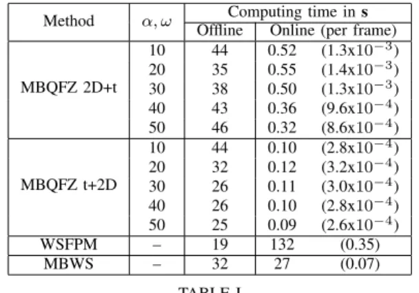
Table I illustrates the computation time required to segment the sequencecarphoneby the2D+tapproach with different (α, ω) parameters. The offline time measures QFZ computation and RAG creation steps, while the online time measures one user interaction, i.e. a single iteration of the graph refinement
a b
c d
Fig. 3. Different steps on frame 186: a) original frame, b) initial QFZ segmentation, c) scribbled markers, d) final segmentation.
step for the whole video sequence (a frame-related measure is also provided). Here the correction of the initial segmentation has not been considered since it only occurs when several markers overlay a single QFZ, which is quite rare in our case since the QFZ build an oversegmentation. Let us observe how-ever that for high values of (α, ω), such a correction may occur more frequently. Nevertheless, in this case online computation time is lowered since the number of QFZ (and subsequently the graph size) is reduced. We also provide in this table a comparison with thewatershed from propagated markers [4] and with the standard marker-based watershed [11] extended to video data (considered here as a3Dvolume). The comparison element is the online time which measures the efficiency of the interactive process (i.e., how long a user has to wait before being informed that she has to provide a new feedback to the segmentation process?). Our method performs far more better than these two methods thanks to its offline preprocessing step. Indeed, when other methods need tens of seconds for the online processing, our method needs less than a second. Though the marker-based QFZ needs more offline processing time than other methods (above two times the needs of [4]), it is totally compensated by the online processing efficiency which is more important in an interactive context.
Besides, we also need to evaluate the precision of the results produced by our method vs. those of other similar works. To do so, we compare our marker-based QFZ to marker-based watershed (MBWS) and seeded region growing (SRG). We choose these two methods because we use MBWS for ill-segmented region refinement and we apply a kind of SRG on our spatio-temporal RAG video representation to obtain the personalized segmentation. The goal of this comparison is to show that our approach, which relies on these basic methods, gives better results than the straight application of them. To perform the precision evaluation, we use an extract of the
Method α, ω Computing time ins
Offline Online (per frame)
MBQFZ 2D+t 10 44 0.52 (1.3x10⁻³) 20 35 0.55 (1.4x10⁻³) 30 38 0.50 (1.3x10⁻³) 40 43 0.36 (9.6x10⁻⁴) 50 46 0.32 (8.6x10⁻⁴) MBQFZ t+2D 10 44 0.10 (2.8x10⁻⁴) 20 32 0.12 (3.2x10⁻⁴) 30 26 0.11 (3.0x10⁻⁴) 40 26 0.10 (2.8x10⁻⁴) 50 25 0.09 (2.6x10⁻⁴) WSFPM – 19 132 (0.35) MBWS – 32 27 (0.07) TABLE I
EFFICIENCY EVALUATION AND COMPARISON OF INTERACTIVE VIDEO SEGMENTATION OF THEcarphoneSEQUENCE:COMPUTATION TIME(IN
SECONDS)REQUIRED BY OUR MARKER-BASEDQFZ (MBQFZ)
ACCORDING TO DIFFERENTαANDωSETTINGS AND TWO OTHER APPROACHES,WATERSHED FROM PROPAGATED MARKERS[4] (WSFPM),
AND STANDARD MARKER-BASED WATERSHED(MBWS).
sequencecarphoneof 80 frames for which we have a ground truth (let us notice that general-purpose spatio-temporal seg-mentation datasets and benchmarks are still missing). We evaluate the results using the mean value of Jaccard-Index which has been used in image segmentation evaluation [12]. Its values are in [0,1], 1 represents a perfect matching between segmentation and reference. We compute it independently for each class and average the result to obtain a global criterion. The different results are obtained by markers set only on the median frame. Results are shown in table II and show that both MBQFZ video approaches gives better results than SRG. We can conclude that our method benefits from applying SRG on QFZ instead of relying on a direct application of the SRG algorithm on video pixels. Moreover, we can observe that our method is able to produce results better or close to those obtained with the marker-based watershed. Let us also note that these results are obtained by different combinations of parameters α,ω and mean area threshold, thus showing a relative robustness of our method to parameter settings. But selecting best parameters for this video segmentation task is still an open problem. While our interactive method is based on the principle of QFZ which is basically an homogeneous region extraction operator, we could expect some difficulties to segment highly textured objects. In practice, as it is illustrated by the segmentation of the outside of the car, our method is able to extract textured object without marking all the different segments of the textured area. This video also shows important motion from both the man and the outside of the car. Even with this motion, our method is able to extract the object marked by the user while not using motion information. This is possible because of the overlapping spatial definition of each object in successive frames. In the case of very fast objects (e.g., a soccer ball) with no spatial overlapping in successive frames, our method will need a motion compensation step to be able to correctly segment these types of object.
Method (α, ω) Area threshold Mean Jaccard-Index MBQFZ 2D+t 30 10 0.905 50 50 0.910 90 50 0.908 MBQFZ t+2D 20 60 0.928 40 100 0.925 100 70 0.919 MBWS - - 0.897 SRG - - 0.548 TABLE II
PRECISION EVALUATION AND COMPARISON OF VIDEO SEGMENTATION OF THEcarphoneSEQUENCE:PRECISION IS EVALUATED BY THE MEAN
JACCARD-INDEX OBTAINED FOR THE THREE OBJECTS(MAN,INSIDE,
OUTSIDE),MARKERS ARE SET ONLY ON THE MEDIAN FRAME. COMPARISON IS MADE ON RESULTS OBTAINED BY MARKER-BASEDQFZ
(MBQFZ)ACCORDING TO DIFFERENTα,ωAND AREA THRESHOLD SETTINGS AND THE RESULTS RETURNED BY THE TWO APPROACHES, SEEDEDREGIONGROWING(SRG),AND STANDARD MARKER-BASED
WATERSHED(MBWS).
that our method provides promising results. In fact, it pro-duces results close to marker-based watershed but requires less online computation time allowing better interaction. It now requires to be more deeply evaluated using a standard benchmark for interactive video segmentation, but we face the lack of such benchmark in the community. Since our current implementation is not optimized yet, some improvements may still be brought to offer a better efficiency (both within the offline part which is not so efficient, and within the online part to offer an even more interactive experience for the end-user). The few experiments presented in this section have been performed using a Java image processing framework developed in our laboratory and run on a i7-720QM processor (1.6 GHz) PC.
VI. CONCLUSION
In this paper, we have addressed the problem of interactive video segmentation. We have introduced a two-step approach where most of the computational effort is first made offline to produce an oversegmentation of the video sequence, while the online interactive step involves user feedback to efficiently return objects-of-interest. Offline segmentation is achieved by computing spatio-temporal quasi-flat zones from the video data and by building a spatio-temporal region adjacency graph. Online process is performed through a marker-based approach where the user draws scribbles over each object-of-interest. User feedback introduced during this online process may even result in a refinement of the initial oversegmentation result.
Future works will focus on the computational optimization of the method in order to demonstrate the relevance of the proposed interactive scheme with high-resolution data. Paral-lelization would help to take advantage of current multi-core processors. Besides, refinement process consisting in online QFZ segmentation needs also to be optimized. Furthermore, we plan to compute and integrate motion information within the QFZ graph in order to improve the merging process. Fi-nally, we have to perform deeper evaluations and comparisons with the state-of-the-art approaches by considering several
criteria such as the qualitative evaluation of the segmentation result (which needs a ground truth to be provided) and the user-time (or number of interactions) needed to achieve this result.
ACKNOWLEDGEMENTS
This work has been supported by Ready Business Sys-tem, Entzheim, France and the French National Association for Research and Technology (ANRT). We particulary thank Christian Dhinaut from RBS for his support.
REFERENCES
[1] J. Weber, S. Lef`evre, and P. Ganc¸arski, “Video object mining: Issues and perspectives,” inIEEE International Conference on Semantic Com-puting, 2010, pp. 85–90.
[2] ——, “Spatio-temporal quasi-flat zones for morphological video seg-mentation,” inInternational Symposium on Mathematical Morphology, vol. 6671, 2011.
[3] B. Price, B. Morse, and S. Cohen, “Livecut: Learning-based interactive video segmentation by evaluation of multiple propagated cues,” inIEEE International Conference on Computer Vision (ICCV), 2009, pp. 779– 786.
[4] F. Flores and R. Lotufo, “Watershed from propagated markers: An interactive method to morphological object segmentation in image sequences,”Image and Vision Computing, vol. 28, no. 11, pp. 1491– 1514, 2010.
[5] X. Bai and G. Sapiro, “A geodesic framework for fast interactive image and video segmentation and matting,” inIEEE International Conference on Computer Vision (ICCV), 2007, pp. 1–8.
[6] L. Zhi and Y. Jie, “Interactive video object segmentation: fast seeded region merging approach,”Electronics Letters, vol. 40, no. 5, pp. 302– 304, 2004.
[7] P. Soille, “Constrained connectivity for hierarchical image partitioning and simplification,” IEEE Trans. on Pattern Analysis and Machine Intelligence, vol. 30, no. 7, pp. 1132–1145, 2008.
[8] J. Serra and P. Salembier, “Connected operators and pyramids,” in Proceedings of SPIE, Non-Linear Algebra and Morphological Image Processing,, vol. 2030, 1993, pp. 65–76.
[9] P. Soille, “On genuine connectivity relations based on logical predi-cates,” inInternational Conference on Image Analysis and Processing, 2007, pp. 487–492.
[10] P. Soille and J. Grazzini, “Constrained connectivity and transition regions,” in International Symposium on Mathematical Morphology, 2009, pp. 59–69.
[11] J. Rivest, S. Beucher, and J. Delhomme, “Marker-controlled segmenta-tion: an application to electrical borehole imaging,”Journal of Electronic Imaging, vol. 1, no. 2, pp. 136–142, 1992.
[12] K. McGuinness and N. O’Connor, “A comparative evaluation of inter-active segmentation algorithms,”Pattern Recognition, vol. 43, no. 2, pp. 434–444, 2010.