Engineering Doctorate in Non-Destructive Evaluation
Thesis
The Development and Implementation of
Advanced Ultrasonic Phased Array
Technology
Jonathan Russell
Abstract
Ultrasonic inspection is the primary technique for the detection of planar flaws within the nuclear industry. Current inspections are typically limited to the application of rigid wedge, single element transducers to components with regular surface geometry. This thesis addresses some of the limitations of this approach and develops new methods and techniques that are suitable for application in an industrial environment.
Inspection modelling is a cost effective technique for inspection design and qualification; it can be used to aid understanding of the inspection process, and provides valuable insight into inspection data interpretation. In this work semi-analytical and numerical modelling tools have been used to accurately and efficiently simulate the ultrasonic inspection of large complex components.
Modelling tools have also been applied to aid in the design of a membrane coupled conformable phased array device. The membrane coupled array is a low-cost, robust device that uses a conventional phased array coupled to the outer surface of the component under test via a water path encapsulated by low-loss membrane. Early design of this device was performed by Long and Cawley at Imperial College, London. The work reviewed in this thesis discussed the further development of this membrane coupled device and its application for the inspection of a specific target application component.
The target application is a safety critical, thick-walled stainless steel section of pipe-work that contains an austenitic weld. The current inspection of this component is carried out by first removing the component weld cap and then mechanically raster scanning a large number of rigid wedge single element transducers. Weld cap removal is an expensive time consuming task that can lead to excessive wall thinning and the exposure of small surface breaking defects. The motivation for this work is to provide complete inspection of the weld and heat affected zone with the weld cap in place. It is also designed to improve inspection speed and accuracy, and to reduce the amount of user intervention required to complete the inspection in a hostile environment.
_____________________________________________________________________ Inspection results from the 2nd and 3rd generation membrane coupled device on multiple test-pieces representative of the target application are presented. These results demonstrate that the membrane coupled device can be used to detect defects in locations that cannot be inspected using conventional techniques. The amount of scanning required can be significantly reduced, simplifying the inspection and helping to improve inspection speed by over 60% in comparison to the single element approach.
Acknowledgements
I would like to thank my supervisor, Peter Cawley for his help and guidance. The level of support that he has provided during my studies has been exceptional and I am very grateful.
My thanks also go to others within the Imperial College NDT group, particularly Mike Lowe and Rob Long whose assistance in this project has been invaluable. I am thankful to Daniel Hesse, Mickael Drozdz and Prabhu Rajagopal for introducing me to finite element modelling and their patience in answering my many questions.
I am grateful to Rolls-Royce for supporting this work and providing an environment in which I could learn and develop my knowledge of NDE. I am especially thankful to Noel Habgood, Lionel Reyes and the following members of the NDE research team – Chris Greener, Martin Mienczakowski, Dave Duxbury, Chris Reed and Iain Baillie.
I would also like to acknowledge the assistance that I have received from individuals within the RCNDE. There are too many to name them all but I’d like to thank everyone involved in the provision of the EngD scheme. I am also grateful to my fellow Research Engineers for their support and for making the various training courses so enjoyable.
I thank my friends and family for their encouragement and patience. Particularly, I want to thank Cathy, without whose support and understanding this would not have been possible.
_____________________________________________________________________
Table of Contents
1. Introduction...1
1.1. Role within Rolls-Royce...3
1.2. Outline of Thesis...8
2. Ultrasonic Inspection ...11
2.1. Background ...11
2.2. Ultrasonic Phased Arrays...22
2.3. Inspection of Components with Irregular Surface Geometry ...31
2.4. Summary ...36
3. Flat Plate, Non-Welded Test-Piece Inspection ...38
3.1. Test-Piece Development ...40 3.2. Technique Description ...45 3.2.1. Corner Echo ...46 3.2.2. Transverse-Longitudinal (TL) Skip ...47 3.2.3. Transverse-Longitudinal-Longitudinal (TLL) Skip...49 3.3. Inspection Development ...52 3.4. Experimental Results ...56 3.4.1. Defect 1...61 3.4.2. Defect 2...63 3.4.3. Defect 4...66 3.4.4. Defect 6...68 3.5. Summary ...70
4. Ultrasonic Inspection Modelling...73
4.1. CIVA...74
4.2. Finite Element Modelling ...76
4.3. Target Application Modelling...83
4.4. Summary ...95
5. Membrane Coupled Device Developments ...97
5.1. Second Generation Membrane Probe Design ...97
5.2. Grating Lobe Internal Noise ...99
5.3. Beam-Spread Internal Noise ...108
5.4. Optimised 80 Element Device Design...113
5.5. 3rd Generation Device Design...117
5.5.1. Coupling...117
5.5.2. 3rd Generation Membrane Device Configurations...119
5.6. 3rd Generation Device Performance...123
5.6.1. Comparison of Irrigation and Immersion Inspection...123
5.6.2. Comparison of Different 3rd Generation Membrane Device Designs127 5.7. Internal Noise Signal Amplitude Variation ...133
5.8. Summary ...136
6. Flat Plate Welded Test-Piece Inspection ...138
6.1. Flat Plate Welded Test-Piece Design...138
6.2. Technique Description ...146 6.2.1. Direct Specular...147 6.2.2. Creep Wave...147 6.2.3. Corner Echo ...148 6.2.4. Transverse-Longitudinal (TL) Skip ...149 6.2.5. Transverse-Longitudinal-Longitudinal (TLL) Skip...150
6.3. Chosen Inspection Techniques for Each Defect ...151
6.4. Inspection Process...156
6.5. Experimental Results ...164
6.5.1. Direct Specular Through Weld Inspection ...165
6.5.2. Creep Wave Inspection ...170
6.5.3. Corner Echo Inspection...171
6.5.4. Transverse-Longitudinal (TL) Skip ...175
6.5.5. Transverse-Longitudinal-Longitudinal (TLL) Skip...176
6.5.6. Inspection Summary ...182
_____________________________________________________________________
6.6.1. Assumptions...186
6.7. Summary ...189
7. Twin Crystal Membrane Coupled Device ...191
7.1. Twin Crystal Transducers ...191
7.2. Inspection Requirements...193
7.3. Twin Crystal Membrane Coupled Device Design ...196
7.4. Inspection Deployment ...205
7.5. Twin Crystal Membrane Device Experimental Results...208
7.6. Summary ...213
8. Conclusions...214
8.1. Review of Thesis...214
8.2. Outline of Main Contributions...217
8.2.1. Membrane Coupled Phased Array Device...219
8.2.2. Inspection Modelling ...221
8.2.3. FMC Based Phased Array Inspection ...222
8.3. Future Work ...222
8.3.1. Twin Crystal Membrane Device...222
8.3.2. Narrow Phased Array Membrane Device ...223
8.3.3. FMC Inspection ...223
8.3.4. Inspection Qualification and Implementation...224
Figures
Figure 2-1 Schematic diagram of a wave at normal incidence to an interface between two media...12 Figure 2-2 Schematic diagram of refraction at a boundary between water and steel. .20 Figure 2-3 The reflection coefficients for longitudinal and shear waves at the
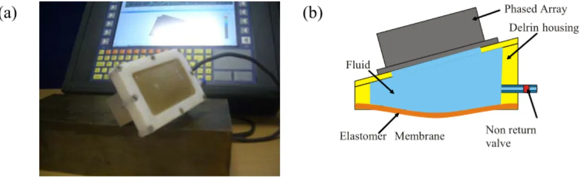
boundary between steel and air, a.) for an incident longitudinal wave and b.) for an incident shear wave...21 Figure 2-4 Common array transducer configurations: (a) linear array, (b) 2D array and (c) annular array, figure taken from (Drinkwater & Wilcox, 2006). ...23 Figure 2-5 Schematic diagram of the required time delays to generate an angled beam using a phased array...25 Figure 2-6 CIVA beam plots for a 2MHz centre frequency contact array on a stainless steel block producing a 45º shear wave with an element pitch of a.) 1.5mm and b.) 0.75mm. Both images are shown with a dynamic range of 40dB. ...27 Figure 2-7 Sector scan of three side drilled hole (SDH) defects, figure taken from (Long & Cawley, 2006). ...28 Figure 2-8 CEA flexible contact array (Chatillon et al, 2000). ...32 Figure 2-9 Commercially available flexible arrays produced by Imasonic (Besançon, France). ...33 Figure 2-10 1st generation membrane coupled phased array device a. photograph and b. device schematic diagram (Long & Cawley, 2006)...34 Figure 2-11 Second generation membrane probe (Long et al, 2007b). ...35 Figure 3-1 Diagram of the target application component...38 Figure 3-2 Schematic diagram of defects contained in the conformable phased array non-welded evaluation blocks, a.) defect 1, b.) defect 2, c.) defect 3, d.) defect 4, e.) defect 5, f.) defect 6. ...43 Figure 3-3 Photograph of the two flat plate, non-welded test-pieces. ...43 Figure 3-4 Schematic diagram of corner echo technique. ...47 Figure 3-5 The reflection coefficients for longitudinal and shear waves at the
boundary between steel and air for an incident shear wave...49 Figure 3-6 Schematic diagram of the Transverse-Longitudinal (TL) skip inspection technique. ...49
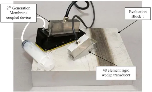
_____________________________________________________________________ Figure 3-7 Schematic diagram of the Transverse-Longitudinal-Longitudinal (TLL) skip inspection technique...50 Figure 3-8 Schematic diagram of the self tandem inspection technique. ...51 Figure 3-9 Photograph of the 2nd generation membrane coupled device and the 48 element rigid wedge linear phased array. ...53 Figure 3-10 Photograph of the 2nd generation membrane coupled device inspection showing the scanning frame configuration. ...55 Figure 3-11 Schematic diagram of the Transverse-Transverse (TT) full-skip
inspection technique...56 Figure 3-12 Schematic diagram of the flat plate non-welded test-piece calibration set-up...58 Figure 3-13 Schematic diagram of the inspection of defect 1 using a.) the 48 element rigid wedge phased array and b.) the 2nd generation membrane coupled device...62 Figure 3-14 Schematic diagram of the inspection of defect 2 using a.) the 48 element rigid wedge phased array and b.) the 2nd generation membrane coupled device...64 Figure 3-15 B-Scan image produced from a. the null defect inspection, and b.) the inspection of defect 2 using the 48 element rigid wedge phased array and c.) using the 2nd generation membrane coupled device. ...65 Figure 3-16 The B-Scan image obtained from the inspection of defect 4 using a.) the 48 element rigid wedge transducer and b.) the 2nd generation membrane coupled device. In the membrane transducer inspection the internal noise signal is the highest amplitude signal and corrupts the image obtained, the SNR has been calculated ignoring this effect. ...68 Figure 3-17 Schematic diagram of the inspection of defect 6 using a.) rigid wedge phased array transducers in transmission and reception, and b.) a rigid wedge
transmitter probe and the 2nd generation membrane coupled device as a receiver...69
Figure 3-18 Comparison of the response from a.) defect 6 and b.) a defect free region. The top surface of the parent plate of the test-piece occurs at 0mm depth so that the weld cap material is deposited above this level and the defect signal appears partially above the component. ...70 Figure 4-1 Schematic diagram of the excitation method used in the FE models. ...79
Figure 4-3 Schematic diagram of ALID usage, a) conventional usage with linear quadrilateral mesh, b) modified usage with quadratic triangular mesh. ...82 Figure 4-4 Schematic diagram of the inspection of defect 2. ...88 Figure 4-5 Comparison of the experimental and simulated A-Scans obtained for defect 2...88 Figure 4-6 Schematic diagram of the inspection of defect 4. ...90 Figure 4-7 Comparison of the experimental and simulated A-Scans obtained for defect 4...90 Figure 4-8 Schematic diagram of the model for defect 5 - lack of sidewall fusion defect at the OD. ...92 Figure 4-9 Comparison of the experimental and simulated A-Scans obtained for defect 5...93 Figure 4-10 Schematic diagram of the beam spread longitudinal-longitudinal wave interaction with defect 5...95 Figure 5-1a.) Schematic diagram of the inspection technique used for the detection of defect 3, b.) B-Scan recorded during the inspection of defect 3 using the membrane probe with FMC, data is post processed to simulate a 65˚ longitudinal wave probe. .98 Figure 5-2 QSonic images based on current membrane probe design a.) No beam steering, b.) Steering to 0º, c.) Steering to shear wave critical angle...101 Figure 5-3 Schematic diagram of the prototype membrane coupled device, showing the main beam and the two associated grating lobes. ...103 Figure 5-4 a.) CIVA beam plot obtained from a 20element aperture using the 2nd generation membrane probe demonstrating the relative amplitude of the main beam and the two grating lobes, image is shown with a dynamic range of 30dB, b.) the echodynamic response along the water/steel interface. ...103 Figure 5-5 Schematic diagram of the prototype membrane coupled device, showing the forward facing grating lobe internal reflection path. ...104 Figure 5-6 Schematic diagrams of the grating lobe reflection path occurring in the 2nd generation membrane coupled device at different angles of incidence, a.) 0º incidence angle, 0º longitudinal wave, b.) 10º incidence angle, 45º longitudinal wave, c.) 20º incidence angle, 45º shear wave. ...105 Figure 5-7 Experimental results obtained using the membrane coupled phased array device, a.) 0º incidence angle, 0º longitudinal wave, b.) 10º incidence angle, 45º longitudinal wave, c.) 20º incidence angle, 45º shear wave. ...107
_____________________________________________________________________ Figure 5-8. Schematic diagram of the beam spread noise signal in a simple case where the main beam is steered to normal incidence. ...109 Figure 5-9. Internal beam spread noise generated in a 0˚ longitudinal wave inspection for the a.) conventional phased array b.) 2nd generation conformable membrane coupled device. ...110 Figure 5-10 Photograph of the bespoke probe jig for internal noise signal
measurements...111 Figure 5-11 B-Scan image generated for a 0˚ longitudinal wave inspection for the 80 element, 15mm, 30º array configuration...113 Figure 5-12 Schematic diagram of the 80 element membrane coupled device
transducer a.) side view, b.) plan view...115 Figure 5-13. Schematic diagram of the optimised membrane coupled device housing. ...115 Figure 5-14. Internal noise signals in the optimised membrane coupled device. ...116 Figure 5-15. Results obtained from the inspection of defect 3 using a.) conventional phased array, b.) optimised conformable membrane coupled device...117 Figure 5-16 3rd generation membrane probe base plate design. ...119 Figure 5-17 Photograph of the 3rd generation membrane coupled device showing the integrated irrigation system...119 Figure 5-18 3rd generation membrane probe design, array has an approximate 6mm first element standoff height and angle of 7º. ...121 Figure 5-19 3rd generation membrane probe design, array has a 20mm first element standoff height and angle of 18º. ...122 Figure 5-20 3rd generation membrane probe design, array has a 6mm first element standoff height and angle of 25º. ...123 Figure 5-21 Schematic diagram of the experimental configuration used to generate a 0º longitudinal wave...128 Figure 5-22 Comparison of the 0º scans generated with beam steering only when positioned to inspect defect 3 using a.) 80el device, b.) 6mm, 7º 128el device, c.) 6mm, 25º 128el device, d.) 20mm, 18º 128el device...129 Figure 5-23 Comparison of the 0º scans generated with beam steering only when
Figure 5-25 45º shear wave inspection of defect 1 showing variable amplitude. The defect response occurs over a broad arc due to beam spread. ...135 Figure 5-26 Schematic diagrams showing the source of internal noise within the membrane coupled phased array a.) on a flat surface, b.) on the rising face of the weld cap. ...136 Figure 6-1 Photograph of the weld cross-section from the flat plate welded test-pieces. ...140 Figure 6-2 Photograph of conformable phased array welded evaluation block 2 (Rolls-Royce, 2008b)...144 Figure 6-3 Schematic diagram of defects contained in the conformable phased array welded evaluation block 1, a.) defect 1, b.) defect 2, c.) defect 5, d.) defect 6, e.) defect 7, f.) defect 8, g.) defect 9, h.) defect 12, i.) defect 13, j.) defect 14...145 Figure 6-4 Schematic diagram of defects contained in the conformable phased array welded evaluation block 2, a.) defect 3, b.) defect 4, c.) defect 10, d.) defect 11. ....146 Figure 6-5 Schematic diagram of direct specular reflection...147 Figure 6-6 Schematic diagram of the creep wave inspection technique...148 Figure 6-7 Schematic diagram of the a.) direct and b.) skip corner echo inspection technique. ...149 Figure 6-8 Schematic diagram of the Transverse-Longitudinal (TL) skip inspection technique. ...150 Figure 6-9 Schematic diagram of the Transverse-Longitudinal-Longitudinal (TLL) skip inspection technique, a.) pitch-catch and b.) self tandem (ST). ...150 Figure 6-10 Weld cap profile of the flat plate welded test-pieces ultrasonically
measured using the membrane device. ...158 Figure 6-11 CIVA beam plots for 3rd generation membrane coupled array coupled to a
water path using unfocused delay laws with a, a.) 17 element aperture and a, b.) 65 element aperture. Both images are shown over a 60dB dynamic range. ...163 Figure 6-12 Schematic diagram to illustrate the through weld inspection of defect 3 using a direct 65º longitudinal wave inspection with the 18º, 20mm device...167 Figure 6-13 60º longitudinal wave B-Scan image obtained from the 17element
aperture inspection of defect 10 through the weld using the 18mm, 20º device. ...168 Figure 6-14 B-Scan image obtained using the secondary through weld scan direction inspection of defect 11 with the 18mm, 20º 3rd generation membrane device. Suitable
_____________________________________________________________________ delay laws have been used to produce 26mm focal depth from an aperture of 31 elements. ...170 Figure 6-15 Schematic diagram of the inspection of a.) a non-defective root in the flat plate welded test-pieces and b.) a root defect. ...173 Figure 6-16 Comparison of the 45º shear wave B-Scan images obtained from a.) defect 8 and b.) a null defect region of the test-piece. ...174 Figure 6-17 Comparison of the 45º full skip shear wave B-Scan images obtained from a.) defect 5 and b.) a null defect region of the test-piece. In each image an unfocused aperture of 17 elements is used and SNR is calculated relative to the background noise. ...175 Figure 6-18 Schematic diagram of the pitch-catch TLL inspection setup...177 Figure 6-19 Schematic diagram of the through weld 65º longitudinal wave TLL inspection set for the inspection of defect 4...180 Figure 6-20 Inspection diagram to detect defect 7 using the 7º, 6mm 3rd generation 128 element membrane probe with a 50º TLL inspection from the positive direction. ...182 Figure 7-1. Schematic diagram of a single element 0º longitudinal wave twin crystal probe. ...192 Figure 7-2. CIVA representation of an angled twin crystal array transducer a.) front view, b.) side view, and c.) plan view...193 Figure 7-3 Schematic diagram of defects considered as part of the twin crystal
membrane coupled phased array development activity , a.) defect 3, b.) defect 4, c.) defect 5, d.) defect 6, e.) defect 10, f.) defect 11, g.) defect 12, h.) defect 13. ...196 Figure 7-4 Plan view of the CIVA representation of a 1.5D phased arrays to generate a variable roof angle twin crystal transducer. ...198 Figure 7-5 CIVA screen capture showing the essential parameters used to design the twin crystal membrane coupled device...200 Figure 7-6 CIVA simulation of the beam produced using null delay laws by a 13º tilt angle twin crystal membrane coupled phased array device with a.) 4º roof angle, b.) 7º roof angle, c.) 7.5º roof angle. All images are shown over a 60dB range. ...203 Figure 7-7 A photograph of the 4º roof angle configuration of the twin crystal
Figure 7-9 Schematic diagram of the surface profile measurement using the twin crystal membrane coupled device...207 Figure 7-10 Photograph of the twin crystal membrane coupled device and the 48 element rigid wedge linear phased array. ...208 Figure 7-11 Schematic diagram of the experimental set-up used for the direct specular through weld detection of defect 3...209 Figure 7-12 Comparison of the 65º longitudinal wave B-Scan images obtained using a 17element aperture with unfocused delay laws for the inspection of defect 10 through the weld using a.) the twin crystal membrane coupled device and b.) the 18mm, 20º 3rd generation linear membrane coupled device. ...211
_____________________________________________________________________
Tables
Table 3-1 Defect Description for flat plate, welded test-pieces...42
Table 3-2 Defect Description for first stage of membrane coupled phased array device inspection development (OD – Outer Diameter). ...52
Table 3-3 SDH calibration experimental data obtained using the 2nd generation membrane device with 45dB gain and the 48 element rigid wedge phased array with 43.25dB gain. ...58
Table 3-4 Experimental results for the inspection of defect 1. ...63
Table 3-5 Experimental results for the inspection of defect 2. ...66
Table 3-6 Experimental results for the inspection of defect 4. ...67
Table 3-7 Experimental results for the inspection of defect 6. ...70
Table 4-1 Summary of the reduction in the overall model size when using ALID absorbing regions for FE models to simulate the single element transducer inspection of defects 1-6...85
Table 4-2 Experimental and simulated TL signals obtained for the inspection of defect 2. The amplitude of each signal has been normalised to unity. ...89
Table 4-3 Comparison of the experimental and simulated TLL signals obtained for the inspection of defect 4. ...91
Table 4-4 Comparison of the experimental and simulated pitch-catch TLL signals obtained for the inspection of defect 5...94
Table 5-1 Summary of the results obtained from the QSonic study to investigate the grating lobes produced by the 2nd generation membrane coupled device over different steering angles...102
Table 5-2 Membrane coupled device grating lobe noise band predicted through geometrical analysis...106
Table 5-3 2nd generation membrane coupled device internal noise band experimental results. ...108
Table 5-4 A comparison of the membrane coupled device beam spread noise predicted through geometrical analysis and found experimentally. ...112
irrigation with internal absorbing material and irrigation with no internal absorbing material. ...125 Table 5-7 Summary of localised signal to noise ratio for the inspection of defect 2 using a 30 mm aperture with the 7º, 6mm membrane coupled device in immersion, irrigation with internal absorbing material and irrigation with no internal absorbing material. ...125 Table 5-8 Summary of localised signal to noise ratio for the inspection of defect 3 using a 30 mm aperture with the 7º, 6mm membrane coupled device in immersion, irrigation with internal absorbing material and irrigation with no internal absorbing material. ...126 Table 5-9 Summary of localised signal to noise ratio for the inspection of defect 4 using the 7º, 6mm membrane coupled device in immersion, irrigation with internal absorbing material and irrigation with no internal absorbing material...126 Table 5-10 Summary of localised signal to noise ratio and signal amplitude for the inspection of defect 1 using the three different 3rd generation membrane device
designs with a 30 mm aperture. ...131 Table 5-11 Summary of localised signal to noise ratio and signal amplitude for the inspection of defect 2 using the three different 3rd generation membrane device
designs with a 30 mm aperture. ...131 Table 5-12 Summary of localised signal to noise ratio and signal amplitude for the inspection of defect 3 using the three different 3rd generation membrane device
designs with a 30 mm aperture. ...131 Table 5-13 Summary of localised signal to noise ratio and signal amplitude for the inspection of defect 4 using the three different 3rd generation membrane device
designs with a 30 mm aperture. ...132 Table 6-1 Defect Description for flat plate, welded test-pieces...142 Table 6-2 Inspection technique summary for the flat plate, welded test-pieces...152 Table 6-3 Membrane coupled device optimum inspection position for defects 1-7. Inspection of the entire volume of interest is performed from six transducer positions relative to the weld, each position is indicated by a unique colour. The colour coding used is discussed in Table 6-4...159 Table 6-4 Colour coding system used to position probe in membrane device
_____________________________________________________________________ Table 6-5 Comparison of 6dB beam width and maximum amplitude obtained from a 17 element aperture and a 65 element aperture using the 3rd generation membrane
device in immersion when using focused and unfocused delay laws...162 Table 6-6 A comparison of the inspection performance for all defects using a direct specular detection technique using single element (yellow shading) and optimised (blue shading) delay laws. Defects that are not detected are indicated by no value for the SNR...166 Table 6-7 A comparison of the inspection performance for all defects using the corner echo inspection technique using single element (yellow shading) and optimised (blue shading) delay laws...172 Table 6-8 A comparison of the inspection performance for the four defects detected using the TL skip technique using single element (yellow shading) and optimised (blue shading) delay laws...176 Table 6-9 A comparison of the inspection performance for all defects using the TLL inspection technique using single element (yellow shading) and optimised (blue shading) delay laws. Defects that are not detected are indicated by no value for the SNR...178 Table 6-10 Table showing the SNR improvement when using an optimised delay law inspection in comparison to a 12.5mm aperture, unfocused inspection. Green shading indicates that it is only possible to detect a defect if optimised delay laws are used. Orange shading implies that a defect can be detected using both delay law approaches. Red shading is used to highlight defects that cannot be detected using a given
technique and grey shading indicates where a specific test is not performed. ...184 Table 6-11 Summary of time required to complete the entire target application
inspection. ...188 Table 7-1 Inspection technique summary for the flat plate, welded test-pieces using the twin crystal membrane coupled phased array device. Grey shading indicates that additional inspection techniques are not deployed. ...195 Table 7-2 Definition of the essential parameters that must be controlled when using CIVA...201 Table 7-3 Comparison of the longitudinal wave refraction angle and beam crossing
Table 7-4 A comparison of the inspection performance for the direct specular through weld inspection of defects 3 and 10 using the 3rd generation linear membrane device
(yellow shading) and the twin crystal membrane device (blue shading). All
inspections are performed using an aperture of 17 elements and unfocused delay laws. Defects that are not detected are indicated by no value for the SNR. ...212
1. Introduction
The Engineering and Physical Sciences Research Council (EPSRC) established the Engineering Doctorate (EngD) scheme in 1992. The Scheme was established to address a belief held by industry, that an alternative research degree to the traditional PhD was required to better prepare researchers for a career in industry. The EngD is a 4 year research degree, which is awarded for industrially relevant research at a level equivalent to a PhD. The research component of the degree is complemented by a number of technical and management courses. The program of training is designed to allow the Research Engineer (RE) to develop the necessary skills to function as an innovative NDE engineer in the future. The UK Research Centre in Non-Destructive Evaluation (RCNDE) was established in 2003 as a focal point for research in Non-Destructive Evaluation (NDE) within the UK. The RCNDE then launched the EngD program in NDE in 2005; I am one of the first cohort of RE’s to participate in the programme.
Rolls-Royce is a world-leading supplier of power solutions. The organization is made up of five individual business units, civil aerospace, defence aerospace, marine, energy and nuclear. Rolls-Royce is a strong supporter of the EngD scheme and has provided industrial sponsorship to a large number of EngD students since the inception of the programme. Rolls-Royce is a full industrial member of the RCNDE, and is currently supporting multiple RE’s in NDE. My EngD is industrially supported by Rolls-Royce Submarines, which is part of the nuclear business unit. Rolls-Royce Submarines is the delegated UK technical authority (TA) for the Nuclear Steam Raising Plant (NSRP) on all Royal Navy submarines.
My EngD research is part of the Nuclear Propulsion Critical Technology (NPCT) project. This is a major Ministry of Defence (MoD) funded research initiative within Rolls-Royce Submarines to research technologies that are essential to the future needs of the naval submarine fleet. The key aims of the overall research project are to improve safety, reduce costs, and maximise availability of the submarine fleet. In the
designed to improve the inspection of the NSRP components with irregular surface geometry. This includes a membrane coupled phased array device and a flexible matrix phased array device. The overall project includes the development of advanced post processing algorithms intended to improve inspection speed, versatility and defect characterisation. Research is also ongoing to develop novel modelling techniques to improve inspection planning, qualification and data interpretation.
As part of the technical authority role Rolls-Royce is responsible for ensuring the safe operation of the NSRP. A major part of this role is the development and deployment of a wide range of NDE based inspections. In-service inspection (ISI) of NSRP components can be particularly challenging. Access constraints present a major difficulty within the submarine environment. Inspections must typically be carried out from the component outer surface only. Also as space on a submarine is very restricted, the area around the component under test during the inspection process is limited. Inspections must be performed in a potentially high radiation area; it is necessary to limit the exposure of personnel to harmful ionising radiation. Therefore automated inspection techniques are developed wherever practically possible and all realistic measures are taken to ensure that radiation dose levels are as low as reasonable practicable (ALARP). The use of automated inspection also helps to ensure that the high integrity testing is performed in as a short time period as possible and that an auditable inspection record can be maintained.
A number of components within the NSRP have a complex geometry which can make inspection even more challenging. Components are designed to fit into a relatively small space, and typically large, regular surfaces are not available as a platform to complete inspection. Many components have some form of irregular surface finish; this can be relatively minor irregularities such slight changes in the surface profile of a forging or more dramatic such as the presence of an undressed weld cap or a change in component cross-section. The conformable phased array technology under development in the advanced NDE NPCT project is specifically designed to address this inspection requirement. The membrane coupled phased array uses a commercial array which is then coupled to the outer surface of the component under test via a water path encapsulated in a low loss rubber membrane. The main focus of my EngD
is the development of a full inspection capability based on this technology and its transfer from academia into Rolls-Royce.
1.1. Role
within Rolls-Royce
My role within the advanced NDE NPCT project has evolved during the four years of my EngD degree. The overall aim of my work has been to introduce the membrane coupled phased array inspection capability into Rolls-Royce. However, I have been involved in a range of additional tasks and have also gradually assumed greater responsibility for my own work and that of others. My initial involvement in the project was to complete a range of finite element (FE) modelling tasks; which will be discussed in greater technical detail in chapter 4. Inspection modelling is routinely carried out by engineers within the Rolls-Royce NDE teams. However, previously this has been limited to the use of simple spreadsheet based models and basic commercial NDE simulation packages. The spreadsheet based models are limited in terms of their functionality and cannot be widely used. The commercial packages are suitable for use in many inspection scenarios but can have limited accuracy. FE modelling offers a means to accurately simulate a broader range of inspections than can be achieved with these commercial packages. However, FE modelling is highly computationally intensive and it can be rather complex to accurately generate appropriate models. Prior to the completion of my research these techniques had not been applied to industrially significant inspection problems within Rolls-Royce.
The development of FE modelling techniques and their application within Rolls-Royce was the primary objective of my research over approximately the first year of my EngD. Nearing the end of this period a target application was selected for the membrane coupled phased array; due to security restrictions it is not possible to provide details of this component and its function in the NSRP. In this report the component will be referred to as the target application. Details of the work performed on the initial development of two flat plate, non-welded test-pieces is described in chapter 3. Upgrades made to the membrane device design based on the results of this initial testing are then reviewed in chapter 5. Results obtained using this modified
further development and the transfer of this technology became the primary focus of my research. My role was to design the inspection of the target application; this involved the design of suitable test-pieces and development of a primary detection technique for each of the artificial defects within the test-pieces. I carried out experimental testing on the test-pieces using single element, conventional phased array transducers and the membrane coupled device. I also simulated a subset of these tests using FE modelling the results of which are discussed in chapter 4.
During my doctorate I have gradually taken on greater responsibility for the overall planning and execution of the entire advanced NDE NPCT project. Initially I assumed responsibility for the organisation of quarterly review meetings with the three Universities. At these meetings the university representatives provide a presentation of the work that they have performed during the previous 3 months. I arrange and then chair the meetings; I also produce minutes from the meetings and provide these to all invitees as a permanent record of the discussion. As I took greater responsibility for the project and as the technologies under development became more mature I also introduced an interim meeting with each of the universities. Typically I visit each individual university four times a year; these meetings are held approximately six weeks after each of the main review meetings. The focus of these meetings is to allow me to gain a greater appreciation of the research work taking place and to provide more focussed support to the university based researchers. These meetings have proved to be a useful tool to ensure that the research remains suitably focussed on industrially relevant problems and that specific problems are addressed quickly.
The flexible matrix array, which is under development at the University of Strathclyde is a relatively immature technology and significant further development will be required before this technology can be deployed on the NSRP. Although I am involved in the development of this device it is not part of my EngD research and will not be reviewed in detail in this document. Likewise much of the research work being carried out at the University of Bristol to develop advanced full matrix capture (FMC) based inspection algorithms including autofocus is not part of my doctorate research and will not be discussed here.
In addition to the increased responsibility for coordinating the advanced NDE NPCT project I have also gradually become more involved determining overall NDE research areas. I have been involved in a number of activities within this role. In order to develop a coherent NDE strategy across the whole of Rolls-Royce, NDE Panel meetings are held where stakeholders from across the business attend. When required I have acted as a secretary at these meetings and published minutes, I have also presented results from my research at this forum. One aspect of these meetings is to discuss specific research areas with applicability across Rolls-Royce and how to most appropriately attract Rolls-Royce funding for this research.
Over the past two years I have provided input into the NDE section of the high-level component and structural integrity research and technology (R&T) strategy document. This document has been developed to ensure that the research work within Rolls-Royce Submarines is suitably coordinated and funded. Through the development of this strategy document it has been possible to identify a number of areas where specific research is needed to address future NDE requirements. More recently I have also been responsible for producing some supporting documentation, briefly describing all of the current and future research areas to be addressed through the NDE R&T strategy. This document is used as a basis for discussing research areas both within and outside the NDE teams.
The main R&T strategy document is updated on an annual basis; based on the result of this process future research work to be addressed through the R&T programme is identified. Research work can be funded through the MoD or directly through Rolls-Royce. In each case in order to obtain funding for a project a proposal document and a range of associated documentation such as project plans and costs must be produced. For the past two years I have produced the bid proposal for the advanced NDE NPCT project which includes all of the University research projects discussed previously. As part of this process I have been responsible for clearly defining the long-term objectives of all four of these tasks and demonstrating how these address the needs of the submarine programme. In the final year of my doctorate my
well in excess of £1million per annum and involving all six members of the NDE research team as well as a number of third party academic and industrial partners.
Each research task funded through the NPCT project must provide a range of tangible benefits and these are reported to the MoD in an appropriate manner. In the advanced NDE NPCT project a detailed report on progress is provided to the MoD on a regular basis throughout the year. I am responsible for generating the progress report related to the advanced array inspection project and I have represented the NDE teams at review meetings with the Rolls-Royce project manager for over two years. I am also responsible for generating an annual progress report related to the project which has been the main annual deliverable associated with this work.
Rolls-Royce submarines subcontract NPCT funded research to a number of different organisations, including other industrial companies as well as academic institutions. In April 08 the Support and Development (S&D) OBU which includes the NDE research team started to subcontract some work to Serco Technical Assurance Services (Serco TAS) (Risley, UK). I am responsible for supervising some aspects of the work performed by Serco TAS under this contract. In this role regularly meet face-to-face with Serco TAS representatives to monitor their progress. I also represent Rolls-Royce on the Inspection Modelling Working Group (IMWG). This is a sub-group established by Serco TAS specifically to address inspection modelling requirements. The IMWG includes users of different modelling platforms from Serco TAS, Rolls-Royce and external experts (Dr R Chapman - British Energy and Prof M. Lowe - Imperial College). I am the representative from the Rolls-Royce S&D OBU and I am responsible for ensuring that the IMWG is addressing the needs of the entire Rolls-Royce department.
The objective of the advanced NDE project is to develop new tools and capabilities that can improve the inspection of NSRP components. In order to understand the requirements of the new technology in this type of application it is important to have an appreciation of the environment in which they are likely to be used. I have spent time working on a submarine completing existing inspections which has given me an insight into the unique challenges that the inspection engineers face. This has
involved completing a number of specific training courses designed to ensure that I can support the inspection in a safe manner.
The EngD is designed to prepare the RE for a senior career in industry, and the combination of technical courses, focused research and industrial experience is well suited to achieving this aim. My research has allowed me to develop a detailed knowledge of ultrasonic inspection and particularly the use of phased arrays. In recognition of this expertise I was asked by Rolls-Royce Aerospace to represent this part of this business in an RCNDE targeted project with University of Bristol, University of Strathclyde and a range of other industrial sponsors. The targeted project is intended to develop the use of 2D ultrasonic phased arrays for NDE applications. This is outside the scope of my EngD but provides an opportunity to gain an understanding of this area. It also gives me an insight into the main NDE drivers for Rolls-Royce Aerospace.
The advanced NDE NPCT project has progressed well and it has been identified as an area that Rolls-Royce would like to support in the future. The scope of this project is also increasing as more of the research topics become further developed and more mature. In order to continue to develop the different research areas and to continue the strong relationship between Rolls-Royce submarines and the RCNDE universities, Royce have decided to support another EngD RE. I was the primary Rolls-Royce contact for the recruitment of the next RE, gathering and assessing applications and interviewing the student who was offered the position. The second RE started his studies in October 2008; I was responsible for outlining the content of his research and have acted as his industrial supervisor on his EngD studies. In addition to my mentoring role with the second Rolls-Royce NDE RE I am also responsible for mentoring Rolls-Royce apprentices as they spend time with the NDE research team. I am also increasingly involved in the direction of work through other researchers within the NDE research team. In order to embed the technologies developed through the advanced NDE NPCT project within Rolls-Royce these capabilities must be transferred to others within the organisation. As the individual responsible for the
As stated above, in addition to the MoD funded projects, some research work is directly funded through Rolls-Royce. I am responsible for the only project that we currently have funded through this route. This is an RCNDE targeted research project to “Array imaging of inhomogeneous steel welds by measurement of weld material maps”. This is a three year research project in collaboration with Imperial College London, University of Manchester and E.On. It is likely that the second RE now working on the advanced NDE NPCT project will also support some aspects of this RCNDE project.
My role within Rolls-Royce is clearly beyond the scope of the typical EngD RE role. I am responsible for a range of activities throughout Rolls-Royce, many of which are beyond the scope of my doctorate. In recognition of the significant additional responsibility that I have taken on during my studies I was offered a position of full-time employment in October 2008. I accepted this offer and during the final 12 months of my doctorate have worked directly for Rolls-Royce. I have taken on many of the additional tasks discussed above as part of this role.
1.2. Outline
of
Thesis
This thesis presents the development of the membrane coupled phased array inspection capability. The aim of this development activity is to provide an improved inspection capability for the NDE of components with complex surface geometry typically found within the nuclear industry. The membrane coupled phased array uses a commercially available linear phased array. The array is then coupled to the surface of the component under test via a water path that is encapsulated by a polyurethane membrane with properties that are well matched acoustically to water.
Chapter 2 provides an overview of ultrasonic inspection techniques. The chapter begins with the physical principles of this approach and discusses conventional single element, rigid wedge inspection techniques. Phased array design and usage is then discussed and the benefits of this approach over single element transducer inspection are highlighted. Two different phased array transducers that are designed to improve the inspection of components with an irregular surface geometry are then introduced. The second of these devices is the membrane coupled phased array device; the focus
of this thesis is the development of inspection techniques for defect detection using this device, defect sizing is not considered.
In order to develop the conformable membrane coupled phased array for use within Rolls-Royce Submarines a specific target application has been selected. The target application component and the inspection of two flat plate, non-welded test-pieces designed to replicate the target application component are described in chapter 3. These test-pieces do not contain an actual weld but do have a representative weld cap. Inspection results comparing the defect detection performance of a rigid wedge phased array transducer to the 2nd generation membrane coupled phased array device are presented and the performance benefits of the flexible array discussed.
In chapter 4 the two primary modelling techniques used in this investigation are described. Simulation of the target application inspection was carried out using the CIVA model and using FE modelling. Results from both modelling approaches are presented and compared to experimental data gathered from the single element transducer inspection of the flat plate, non-welded test-pieces.
Development of the 3rd generation membrane coupled phased array transducer is described in chapter 5. In comparison to the 2nd generation design this device provides a reduced level of internal noise and improved beam forming characteristics. The 3rd generation device also incorporates an integrated irrigation system which is required for the deployment of this transducer in a commercial inspection.
Results from the inspection of two flat plate, welded test-pieces using the 3rd
generation membrane coupled device are presented in chapter 6. These test-pieces contain a weld and weld cap representative of the actual target application component and 14 different artificial defects. Each defect is inspected using multiple techniques from both directions either side of the weld. All defects can be positively detected by at least one of the inspection techniques used.
twin crystal membrane coupled device, designed to eliminate this issue and improve the inspection of some challenging defects is reviewed and assessed in chapter 7. Preliminary results obtained using the twin crystal device are presented, which demonstrate that the internal noise signal has been eliminated and that improved inspection performance is possible by using this device.
The main conclusions of this thesis and ideas for future work are presented in chapter 8.
2. Ultrasonic Inspection
Ultrasonic testing (UT) is a well-established Non-Destructive Evaluation (NDE) method using high frequency acoustic energy, usually in the range 1-5MHz, to conduct measurements (Birks & Green, 1991). It is a highly versatile method of testing and can be used in a number of different situations including flaw detection/evaluation, dimensional measurements, and material characterization (Mitsui Babcock, 2005).
Ultrasonic inspection is one of the major NDE techniques used within the nuclear industry and represents the biggest area of NDE research and development within Rolls-Royce Submarines. In this chapter, the basic principles of bulk wave ultrasonic inspection are reviewed, along with the use of phased array inspection techniques and the use of flexible arrays for the inspection of components with irregular surface geometry. This is not an exhaustive review of all uses of ultrasonic inspection, but focuses on the techniques and the applications of these techniques that are relevant to the nuclear industry.
2.1. Background
Ultrasonic energy is commonly introduced into the material using a piezoelectric transducer. Piezoelectric materials produce an electrical charge when subjected to a mechanical stress, equally when electrically excited these materials become stressed (Auld, 1973; Cheeke, 2002). The direct piezoelectric effect occurs when stress is applied to the piezoelectric material. In this situation bound electric charges appear at opposing surfaces of the medium, causing a difference in potential across the medium. The direct piezoelectric effect is always accompanied by the indirect, or converse piezoelectric effect. The indirect piezoelectric effect corresponds to the induced stress in a material when subjected to an applied voltage.
In a simple contact transducer, operating as a transmitter in pulse echo mode an electrical pulse is sent to the transducer. This produces motion in the piezoelectric element, via the indirect piezoelectric effect which then generates an acoustic wave in
transducer through the direct piezoelectric effect. This voltage is then detected and interpretation of these signals is used to infer information related to the component being inspected.
The ultrasonic energy produced by the transducer propagates through the material under test until there is a change in acoustic impedance. Acoustic impedance is the product of the velocity of sound within a material and the density of that material. When the wave encounters an interface between two different media, reflection and transmission of the wave occurs. When calculating the behaviour of the wave at the interface between the two media the boundary conditions must be satisfied. At the interface the two boundaries are connected and hence there is continuity of the normal and tangential components of displacement and stress. The simple case of a pressure wave traveling in the positive x-direction at normal incidence to an infinite interface at x=0 between two media is shown in the schematic diagram in Fig 2-1.
p
i
p
t
p
r
x=0
Material 1
Material 2
Figure 2-1 Schematic diagram of a wave at normal incidence to an interface between two media.
The three waves shown in Fig 2-1 can be represented as:
) ( expi t k1x A pi = i ω − ) ( expi t k1x A pr = r ω + (2.1) ) ( expi t k2x A pt = t ω −
Where p = Pressure
A = Amplitude
ω = Angular frequency
t = Time
k = Wavenumber
Tp = Transmission coefficient for pressure Rp = Reflection coefficient for pressure
As discussed above, there must be continuity of displacement (velocity) and stress (pressure); therefore at the boundary it follows that:
t r i p p p + = (2.2) t r i P P P + = (2.3)
Equations (2.2) and (2.3) can be solved to give the pressure transmission and reflection coefficients for normal incidence. In each case the phase of the wave is given by the sign of the coefficient:
2 1 2 2 Z Z Z T P P P i t + = = (2.4) 2 1 1 2 Z Z Z Z R P P P i r + − = = (2.5)
Where Z1 = Impedance of material 1 Z2 = Impedance of material 2
Therefore from the definition of acoustic intensity:
Z p I 2 2 = (2.6)
It follows that the energy transmission and reflection coefficients for normal incidence are given by equations (2.7) and (2.8) respectively.
2 2 1 2 1 ) ( 4 Z Z Z Z TE + = (2.7) 2 1 2 1 2 ⎟⎟ ⎠ ⎞ ⎜⎜ ⎝ ⎛ + − = Z Z Z Z RE (2.8)
The transmission and reflection coefficients will also vary with the angle of incidence and depending on whether the two materials are liquids or solids. All of these cases are covered by standard texts on ultrasonic waves such as Cheeke (2002), Auld (1973b) and Schmerr (1998).
The difference in acoustic impedance between a solid and air is very large; therefore if the wave encounters a crack filled with air almost all of the wave energy will be reflected. In this scenario, the phase of the reflected wave will also be reversed in comparison to the incident wave. The presence of a defect can be detected by either the increase in the reflected signal or the reduction in the transmitted signal. Since the velocity of sound within the material is known the time taken for the transmitted signal to propagate through the material and reflect from the defect back to the receiver can be used to calculate the defect position. By studying the nature of the signal it is often possible to infer further information concerning the type of defect present.
Ultrasonic inspection is essentially a point technique; only the region in the immediate vicinity of the transducer is irradiated with ultrasonic energy. Therefore the transducer must be scanned over the surface of the specimen under test. This procedure can be automated or performed manually. Automated scanning provides an accurate permanent record of the defect but it is time consuming and expensive. It is also very challenging on curved or complex geometries. Manual scanning is faster and more flexible but no permanent record of the scanning is available and the inspection reliability is highly dependent on human factors (Lemaitre et al, 1996). In the majority of inspections carried out by Rolls-Royce Submarines and within the
nuclear industry generally the benefits of completing a high integrity automated inspection outweigh the cost implications. This approach has been adopted to generate the experimental data reviewed later in this document.
Under most circumstances a coupling medium is also required between the transducer and the component. As previously mentioned there is a large acoustic impedance mismatch between the solid and air. This allows defects to be detected within the solid material but reduces transmission between the transducer and the component under test. This air gap must generally be eliminated to effectively couple the transducer to the component. This can be achieved by immersing the component in a water tank. However, this is usually unsuitable for particularly bulky specimens or when the specimen cannot be moved. Alternatively a coupling medium, usually a gel or water, can be used. Lack of coupling is a common cause of poor results and care must be taken to ensure good ultrasonic contact is maintained throughout the test.
Ultrasonic energy can travel through a material in a number of different ways. The main wave modes relevant to this testing will be discussed. If we first consider a 1-dimensional case for a small element of length, l, and density, ρ, undergoing an elongation of ∂udue to an external force, F in the positive x-direction. The external stress is given by equation (2.9), where A represents the area of the element:
A F
p= (2.9)
Hooke’s law can be written as: ε E
p= (2.10)
Where E = Young’s Modulus
Assuming small strains only, then: x u l u ∂ ∂ = ∂ = ε (2.11)
Newton’s second law can be written as:
2 2 t u x p ∂ ∂ = ∂ ∂ ρ (2.12)
The 1-dimensional wave equation is then obtained by combining Hooke’s law with equation (2.12): 2 2 2 2 t u E x u ∂ ∂ = ∂ ∂ ρ (2.13)
The velocity of the wave is given by:
ρ
E
c= (2.14)
By substituting equation (2.14) into equation (2.13), we can rewrite the wave equation as: 2 2 2 2 2 1 t u c x u ∂ ∂ = ∂ ∂ (2.15)
It is possible to show that this result can be then be extended to 3-dimensions, this is provided in standard texts (Cheeke, 2002; Schmerr, 1998) and shown in vector notation in equation (2.16) 2 2 2 ( ) ( ) t ∂ ∂ = • ∇ ∇ + + ∇ u λ μ u ρ u μ (2.16)
Liquids cannot support shear stresses and therefore only support longitudinal or compression waves and the bulk modulus of the material should be considered, whereas solids offer elastic resistance to shearing forces, therefore, solids can support both longitudinal and shear or transverse waves. In solids, the compression modulus of the material, which is a combination of the bulk modulus and the shear modulus, is used. In longitudinal wave propagation the particle displacement is in the same plane as the direction of wave propagation. In shear waves the particle displacement is perpendicular to the direction of the wave propagation and can occur in two orthogonal polarizations. Solids can support both vertically and horizontally polarized shear waves. However, due to their mode of operation, piezoelectric transducers typically are used to produce vertically polarized shear waves only and this type of wave has been used throughout the experimental work detailed in this thesis.
Separation of the longitudinal and transverse wave modes can be achieved by the Helmholtz decomposition (Lowe, 1992). The displacement vector is decomposed into a scalar function Θ to represent the longitudinal wave, and a vector function ψ, to represent the shear wave.
ψ
×
∇
+
Θ
∇
=
u
(2.17)The 3-D wave equation in (2.16) can then be satisfied if the functions Θ and ψ satisfy the following equations:
0 1 2 2 2 = ∂ Θ ∂ − Θ ∇ t cL (2.18) 0 1 2 2 2 = ∂ ∂ − ∇ t cS
ψ
ψ
which have two distinct wave speeds, which can be described in terms of the Lamé constants: λ and µ: ρ μ λ+2 = L c (2.19) ρ μ = S c (2.20)
The Lamé constants are related to Young’s modulus, E, and Poisson’s ratio, νby the following equations: ) 2 1 )( 1 ( υ υ υ λ − + = E (2.21) and ) 1 ( 1 ν μ + = E (2.21)
When propagating at a sufficient distance from the material boundaries that no interaction between the wave and material boundaries occurs, both shear and longitudinal waves act as in an infinite medium and are known collectively as bulk waves.
Solid materials also support Rayleigh waves which travel along the surface of the solid. Rayleigh waves propagate with a mixture of longitudinal and shear wave motion. Therefore, the particle motion of a Rayleigh wave is elliptical, with the major axis of particle displacement perpendicular to the direction of propagation. Rayleigh waves are constrained to exist in only 2-dimensions and only extend a distance approximately equal to one wavelength into the material. Rayleigh waves follow the surface geometry of a part; the waves can travel long distances but are damped by surface roughness and by any moisture that is present on the material surface (Auld, 1973b; Cheeke, 2002; Krautkramer & Krautkramer, 1983; Schmerr, 1998).
Ultrasonic waves obey Snell’s law at a material interface. Snell’s law is provided in equation (2.22). 2 1 2 1 sin sin v v = θ θ (2.22)
Where θ1 = Angle in material 1 θ2 = Angle in material 2
v1 = Propagation velocity in material 1 v2 = Propagation velocity in material 2
The angle of refraction within a given material is different for each of the different types of wave modes that propagate through a material. This is because each of the different wave modes propagates with a different velocity through the material. Therefore different modes can be excited within a component by changing the angle of incidence of the transducer. This is shown the schematic diagram in Fig 2-2 for an inspection in immersion where the incident angle is given by θi, and the angle of the
longitudinal and shear waves are θl and θs respectively. The generation of a shear
wave within a solid from an incident longitudinal wave is known as refractive mode conversion. In immersion testing this is achieved by simply moving the transducer relative to the component. In contact testing a wedge of material (typically Perspex or similar) is introduced between the transducer and the component. The relative intensity of the different wave modes within a solid is dependent on the angle of incidence. The incidence angle of the transducer can be optimized to detect a certain type and position of the defect.
θ
iθ
iθ
sθ
lWater
Steel
Figure 2-2 Schematic diagram of refraction at a boundary between water and steel.
If the angle of the incident longitudinal wave is gradually increased the angle of the refracted longitudinal wave also gradually increases. At a certain angle, known as the first critical angle, the angle of the refraction of this wave is equal to 90º. At this incident angle only a bulk shear wave is generated in the material. If the angle of incidence is increased further the refracted shear wave will also eventually reach 90º, this point is known as the second critical angle. As the refraction angle is increased further still the Rayleigh wave angle is reached, at this point there is only a surface wave generated within the material. The first and second critical angles can be readily calculated from equation (2.22). At an angle just below the first critical angle a creep wave or subsurface longitudinal wave is generated in the material.
Within the solid test medium, reflective mode conversion can occur at the boundary of the component. If a longitudinal wave is incident on a boundary at a given angle of incidence then a longitudinal wave will be reflected at an angle equal to the angle of incidence; a shear wave will also be generated at a different angle. As in the refracted case the relative intensity of the two reflected waves will depend on the angle of incidence. The same phenomenon occurs for an incident shear, both shear and
compression waves being reflected from the surface at different angles and intensities. The reflection coefficients for longitudinal and shear waves at the boundary between steel and air is provided in Fig 2-3. These reflection coefficients have been calculated using the software package Spectrum (Spectrum; Pialucha, 1992). The case for an incident longitudinal wave is shown in Fig2-3a and that for an incident shear wave is provided in Fig 2-3b. a.) b.) 0 0.2 0.4 0.6 0.8 1 1.2 1.4 1.6 1.8 2 0 10 20 30 40 50 60 70 80 90
Shear Wave Angle of Incidence (Degrees)
R e flect ion co re ffi ci en t
Reflected Longitudinal Wave (RL) Reflected Shear Wave (RS)
Steel Air S RS RL θ 0 0.2 0.4 0.6 0.8 1 1.2 0 10 20 30 40 50 60 70 80 90
Longitudinal Wave Angle of Incidence (degrees)
R e flect ion C oef fici en t
Reflected Longitudinal Wave (RL) Reflected Shear Wave (RS)
θ
L RS
RL Steel
Further information on ultrasonic wave propagation and testing is provided in standard reference textbooks (Birks & Green, 1991; Drury; 1983; Henneke et al, 1991; Krautkramer & Krautkramer, 1983).
2.2. Ultrasonic
Phased
Arrays
Historically ultrasonic inspection has been performed using individual transducers; these have been reviewed in a range of texts (Krautkramer & Krautkramer, 1983; Birks & Green, 1991). A single transducer can be used to complete testing in pulse-echo where the transducer is used as both a transmitter and receiver. Pitch-catch and through transmission inspections have also been developed where separate transmitter and receiver probes are used. In each of these techniques fixed angle transducers are used, which insonify a limited inspection volume within the component under test. All of these are point techniques and the probes must be mechanically scanned to build up an image of the component. If defects can occur at different orientations, as is commonly the case in metallic structures, then the inspection must be repeated with a number of different angle probes.
Phased arrays are arrangements of small individual transducers, which are referred to as the elements of the array. The arrangement of the elements within the array controls its basic operation. Linear arrays, shown in Fig 2-4a, are also referred to as 1D arrays; this type of array allows beam steering and focusing anywhere within a 2D imaging plane. Planar or mosaic arrays, shown in Fig 2-4b, contain a number of elements that are arranged in a 2D grid, some work has been done on the optimization of the grid configuration (Martinez et al, 2003; Norton, 1992; Mondal et al, 2005). This type of array allows beam steering and focusing anywhere in a 3D inspection volume. Annular arrays, shown in Fig 2-4c, are circular, these arrays do not allow beam steering but they do provide variable focal depth capability. Different array designs are reviewed in detail elsewhere (Drinkwater & Wilcox, 2006; Shung, 2002).
Figure 2-4 Common array transducer configurations: (a) linear array, (b) 2D array and (c) annular array, figure taken from (Drinkwater & Wilcox, 2006).
The manufacture and operation of 2D arrays is relatively complex, thus increasing cost and difficulty of production. Also limitations in array controller technology and computing power mean that the size of arrays is currently limited to a relatively small number of elements. Therefore, although some applications have been reported (Casula et al, 2005; Akhnak et al, 2002), they are yet to find widespread use in industry. In many inspections defects can occur at a range of angles. Beam steering is therefore important and so annular arrays find limited application. At the current time linear arrays are by far the most commonly used in industrial NDE.
Linear arrays typically contain a number of rectangular array elements arranged side by side. Elements within the array are normally relatively long and narrow so that they behave approximately like line sources. A perfect line source would generate a semi-cylindrical wavefront. However, the element has a finite width, this reduces the amount of beam spread and hence the width of the beam generated. The length of the element, the y-dimension in Fig 2-4, is significantly greater than the wavelength thus minimizing acoustic beam-spread in this dimension.
in the phased array is electrically isolated from its neighbours. This is achieved by connecting each element with an individual electrical delay line; these delay lines are then all connected to a multiplexer. This allows each element to be independently addressed, providing beam steering and focusing in both transmission and reception. As the ultrasound is generated in the same way as for single element probes, similar requirements exist to couple the ultrasound into the component. Testing must once again be performed using some form of suitable coupling medium to prevent large interface reflections.
The beam profile generated by a single element probe is controlled by the mechanical design of the probe. The field generated by the probe is fixed and cannot be changed. Phased array transducers are much more flexible, and they can typically be used to mimic the fields generated from a range of different single element probes. This flexibility means that a wide range of testing regimes can be implemented with a single phased array transducer. Individual elements or a group of elements (termed the aperture) can be fired in-phase with one another to generate a plane wave within a component. Alternatively different delays can be applied to each element to steer or focus the beam. A different set of delay laws (or focal laws) is required for each different test case.
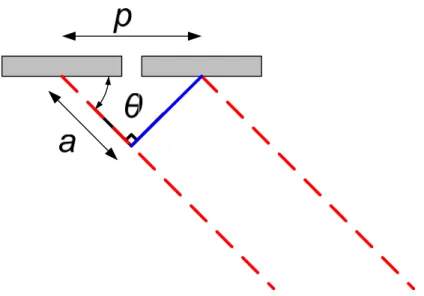
The array operation is shown for the simple case of beam steering in the schematic diagram provided in Fig 2-5. In order to generate the plane wavefront indicated by the solid blue line in Fig 2-5 the timing delays applied to two adjacent elements must be suitably controlled to ensure that constructive interference occurs along this line. The signal from the first element must travel a distance a calculated from equation (2.23) before the second element is fired. The time delay t, required for a wave to travel this distance at a velocity c, within the test medium is then found from equation (2.24) θ cos p a= (2.23) c p t= cosθ (2.24)