First edition,
March
2009
Engineering in the Water Environment
Good Practice Guide
Temporary
Construction Methods
Your comments
SEPA is committed to ensuring its Good Practice
Guides are useful and relevant to those carrying out activities in Scotland’s water environment.
We welcome your comments on this Good Practice Guide so that we can improve future
editions.
A feedback form and details on how to send your
comments to us can be found at the back of this guide in Appendix 1.
Engineering in the Water Environment Good Practice Guide: Temporary Construction Methods
First edition, March 2009
(Document reference: WAT-SG-29)
Contents
1 Introduction 3
1.1 What’s included in this Guide? 4
2 Impact of the construction phase on the water environment 6
2.1 Pollution 6
2.2 Damage to habitats 7
3 Good practice guidance 9
3.1 Planning and site set-up 9
3.2 Site clearance 12
3.3 Minimise run-off of contaminated water 14
3.4 Isolation of works area 20
3.5 De-watering of isolated area 37
3.6 Treatment and/or disposal of contaminated water 39
3.7 Temporary river crossings 43
3.8 Re-instatement of bed and banks 50
1 Introduction
This document is one of a series of good practice guides produced by SEPA to help people involved in the selection of sustainable engineering solutions that minimise harm to the water environment. This Guide is intended for use by those considering engineering activities in rivers or lochs and SEPA staff.
SEPA expects all new engineering activities authorised under the Water Environment Water Environment (Controlled Activities) (Scotland) Regulations 2011 (“CAR”).– also known as the Controlled Activities Regulations or CAR– to follow good practice. Good practice is defined as the course of action that serves a demonstrated need and is sustainable (ie the work is justified and the chosen design is effective), while minimising ecological harm and at a cost that is not disproportionately high.
Applicants proposing to undertake an engineering activity will be expected to demonstrate to SEPA that good practice has been adopted (see box below). Part of this involves ensuring that harm to the environment is minimised during the construction phase (question 5 below). This Guide is designed to help applicants:
• ensure good practice is carried out during the construction phase for all engineering activities in the water environment;
• help provide the information required in the CAR application form.
Summary of SEPA good practice tests 1. Have you demonstrated a need for the proposed activity? 2. Have you considered appropriate alternative approaches? 3. Does the proposal represent the best environmental option? 4. Is the activity designed appropriately?
5. Have all necessary steps been taken to minimise the risk of pollution and damage to habitat or flora/fauna during construction?
This document is not intended as a technical design manual. It is important to recognise that any engineering works must be designed to suit site-specific conditions. This document addresses the environmental aspects that should be considered when undertaking a project.
Under the Controlled Activities Regulations new engineering activities in
Scotland’s rivers, lochs and wetlands require an authorisation from SEPA. More information is available in the CAR Practical Guide
http://www.sepa.org.uk/regulations/water/
Oil must be stored in accordance with the Water Environment (Oil Storage) (Scotland) Regulations 2006. The Regulations apply to any kind of oil including petrol, diesel, mineral oil, heating oil, lubricating oil, waste oil, vegetable and plant oil. More information on these regulations and when they apply can be found on the SEPA website
http://www.sepa.org.uk/regulations/water/pollution-control/scottish-oil-storage-regulations/
1.1 What’s included in this Guide?
This Guide focuses on temporary construction works required when working in rivers or lochs. It does not cover pollution prevention measures for the wider construction site. There is already considerable guidance (see box below) on preventing pollution from construction sites, which should be considered along with the guidance given in this Guide.
The good practice guidance given in Section 3 of this Guide covers the following tasks: • planning and site set-up;
• site clearance; • minimising run-off; • isolation of works area; • de-watering of isolated area;
• treatment/disposal of contaminated water; • temporary river crossings;
• reinstatement of bed/banks.
Colour coded boxes in this guide highlight key information.
Green boxes provide summaries of important points.
Blue boxes provide details of other useful sources of information.
Guidance on preventing pollution from construction sites CIRIA publications – available from https://www.ciria.org/
• Control of Water Pollution from Construction Sites – Guide to Good Practice (SP156)
• Control of Water Pollution from Construction Sites – Guidance for Consultants and Contractors (C532)
• Control of Water Pollution from Linear Construction Projects – Technical Guidance (C648)
• Control of Water Pollution from Linear Construction Projects – Site Guide (C649)
• Environmental Good Practice – Site Guide (C650) • The SUDS Manual (C697)
• Site Handbook for the Construction of SUDS (C698)
Pollution prevention guidance published jointly by Environment Agency, SEPA and Environment and Heritage Service:
• Getting Your Site Right. Industrial and Commercial Pollution Prevention.
www.environment-agency.gov.uk/static/documents/Business/pp_pays_booklet_e_1212832.pdf • Pollution Prevention Guideline (PPG) 5: Works and Maintenance In or Near
Water
• Pollution Prevention Guideline (PPG) 6: Working at Construction and Demolition Sites
• Pollution Prevention Guideline (PPG) 21: Pollution Incident Response Planning
• Pollution Prevention Guideline (PPG) 18: Managing Fire Water and Major Spillages
2 Impact of the construction phase on the water environment
Although the construction phase of any project is short term compared with the permanent works that are being built, the risk of pollution and damage to the water environment during this phase is very high. These risks are summarised below.
2.1 Pollution
Scotland generally experiences the highest annual rainfall in the UK. But within Scotland rainfall can vary considerably; in parts of the West Highlands annual rainfall can be up to 3m compared to less than 800mm in parts of the east coast. This is an important consideration for construction works in Scotland, as rainfall increases the risks of pollution and damage to the water environment also increase.
Rainfall and associated surface water run-off during construction works can mobilise and transport pollutants such as sediment, oils, chemicals and other building materials into the water environment causing harm to plants and animals. Heavy rainfall can also flood excavations and other work areas which subsequently require draining or de-watering. When working in or near rivers, construction sites are more at risk of flooding from rising river levels.
Pollution from sediment and other pollutants can come from a number of sources on construction sites (see box below).
Potential sources of pollution on construction sites
• Direct disturbance of the banks and bed of rivers and lochs • De-watering of excavations
• Run-off from exposed ground and material stockpiles • Run-off from roads and haul routes and river crossings • Plant washings/washing areas
• Fuel and chemical storage/refuelling areas • Leaking/vandalised equipment
Impacts of pollution can include the following.
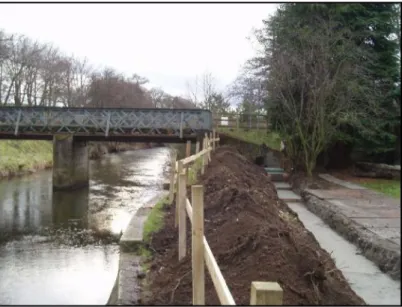
• Sediment pollution can smother important river habitats such as fish spawning habitats (see Figure 1).
• Pollution from fuels and other chemicals can have a variety of effects on fresh water ecology and can lead to fish and invertebrates being killed in lochs and along long lengths of river.
• Cement pollution of waters results in high alkalinity and raises the pH, which can be toxic to aquatic life.
• Even very small amounts of material can be a pollutant. For example, five litres of oil can disperse to cover an area of water the size of four football pitches.
• All these forms of pollution can also render receiving waters unsuitable for potable or industrial abstraction, fish farming, angling, agricultural stock watering, and general amenity/tourism.
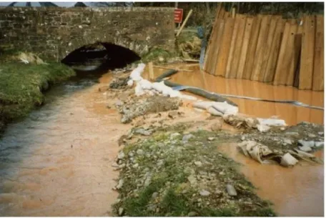
Figure 1
X
Poor practice on a construction site leading to polluted surface water run-off2.2 Damage to habitats
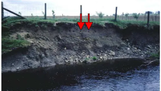
Important habitats, including protected habitats and species, can be lost during the construction phase both through direct loss during site clearance (see Figure 2) or indirectly due to loss through pollution and/or disruption. For example, if a temporary crossing is a barrier to fish passage at key migratory times, fish will be prevented from reaching upstream spawning grounds. Otter holts/water vole colonies/salmonid and lamprey spawning areas could be destroyed. There is also the risk of spreading invasive non-native plants such as Japanese knotweed during construction. In the worst cases, long-term or even permanent damage may occur.
Figure 2 Habitats such as sand martin burrows can be destroyed during the construction phase
Most pollution incidents are avoidable and the risk of pollution and damage to the water environment can be reduced by careful planning.
Planning stage considerations:
• Identify the location of all watercourses, lochs, wetlands and drainage paths for surface water.
• Identify protected habitats and species. • Assess potential flood risks.
• Identify potential sources of pollution (see Section 2). • Timing of works.
• Space should be put aside for Sustainable Urban Drainage Systems (SUDS) or SUDS equivalent.
• Train staff.
• Emergency procedures. • Monitoring requirements.
3 Good practice guidance
3.1 Planning and site set-up
The risk of pollution and damage to the water environment should be minimised by careful planning. The following should be considered at the planning stage.
Location of surface waters
Identify the location of all rivers, lochs, wetlands, burns, ditches, drains and drainage paths for surface water and how the proposed works will affect them by undertaking an appropriate pre-works survey (desk-based and on-site verification). Buffer strips and working/storage distances from watercourses should be considered.
Protected habitats / species
Identify key habitats and designated areas on or adjacent to the site, eg Sites of Special Scientific Interest (SSSIs), Special Areas of Conservation (SACs), RAMSAR sites.
Flood risk
Assess potential flood risks to the site during the works. Check the SEPA Indicative River & Coastal Flood Map (http://www.sepa.org.uk/environment/water/flooding/flood-maps/) for an indication of the extent of site likely to be affected by flooding.
Sources of pollution
Identify potential sources of pollution (see Section 2). Also consider methods of disposing of contaminated water.
Space for SUDS
Put aside adequate space for SUDS including facilities such as settlement ponds during construction stages of a project. Where the construction will lead to a permanent facility requiring surface water drainage, consider how systems deployed to treat run-off during construction might be retained or converted into permanent SUDS to serve the built structure once completed.
Train staff
All personnel from the site manager to engineers, foremen, plant operatives, sub-contractors, tradesmen and labourers have a part to play in preventing pollution and harm to the water environment during construction. It is crucial that each member of the site staff is aware of the potential impact of their activities and is equipped with the knowledge of how to eliminate or reduce that impact. Lack of training and awareness of environmental impact can often result in bad practices unwittingly being adopted. Bad practices can in turn lead to pollution or degradation of adjacent rivers, lochs and wetlands.
Emergency procedures
At the project planning stage it is essential to think through the possible incidents and emergencies which could arise during construction works and plan accordingly (risk assessments). These may include:
• pollution incidents – spillages, failure of temporary works, bank collapse, vandalism, fire, etc;
• extreme weather events – heavy rainfall, flooding, severe frost and snow.
Put in place an emergency response plan on site with a procedure for dealing with emergencies and communicate this procedure to all site staff at site induction.
Site staff responsible for taking action in emergencies must be: • aware of their responsibilities;
• trained to use the necessary equipment such as spill control equipment and shut-off valves.
For further guidance, refer to the following Pollution Prevention Guidelines (PPGs) (www.environment-agency.gov.uk/netregs/links/63893.aspx):
• PPG 21: Pollution Incident Response Planning; • PPG 18: Managing Fire Water and Major Spillages.
PPG21 includes an example of a typical pollution incident response plan which could be amended to suit different site situations.
Variations
No matter how well planned a construction project, variations to the permanent works, temporary works, programme or work methods are often necessary. If not carefully considered even minor variations can have a significant impact on the water environment. It is therefore vital that the need for a variation is communicated clearly from the site to the person with overall responsibility for environmental matters. Allow this person sufficient time
Sources of further information on good practice in planning and site set up CIRIA publications – available from https://www.ciria.org/
• Control of Water Pollution from Construction Sites – Guidance for Consultants and Contractors (C532)
• Control of Water Pollution from Linear Construction Projects – Technical Guidance (C648)
• Control of Water Pollution from Linear Construction Projects – Site Guide (C649)
• Environmental Good Practice – Site Guide (C650) • The SUDS Manual (C697)
• Site Handbook for the Construction of SUDS (C698)
Pollution prevention guidance published jointly by Environment Agency, SEPA and Environment and Heritage Service:
• Getting Your Site Right. Industrial and Commercial Pollution Prevention.
www.environment-agency.gov.uk/static/documents/Business/pp_pays_booklet_e_1212832.pdf • PPG5: Works and Maintenance In or Near Water
• PPG6: Working at Construction and Demolition Sites • PPG18: Managing Fire Water and Major Spillages • PPG21: Pollution Incident Response Planning
PPGs are available from the NetRegs website (www.environment-agency.gov.uk/netregs/links/63893.aspx).
to assess the risks to the water environment and to consult with the designer before any variation is implemented.
For substantial or significant variations, it may be necessary to consult SEPA or submit revised details construction and method statements for approval. If there is any doubt about the impact of a variation, SEPA should be consulted.
Monitoring requirements
Monitoring can help determine if construction works are having an impact on the water environment. This can help assess the effectiveness of pollution prevention measures and give early warning of pollution incidents so that corrective action can be taken.
3.2 Site clearance
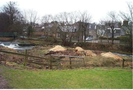
During site clearance (vegetation removal and demolition operations) rivers, lochs and wetlands are particularly vulnerable to loss of wildlife habitats and pollution (see Figure 3).
Figure 3 Tree clearing prior to river engineering works
Avoid unnecessary vegetation clearance. This keeps damage to a minimum and helps prevent sediment pollution from run-off. Only clear vegetation when works are required; adopt a phased approach to avoid clearing the whole site at once, leaving exposed ground for long periods of time.
Establish buffer zones around watercourses and protected habitats/species. Do not disturb protected habitats/species and establish exclusion zones that are suitably isolated from works using fences, barriers, screens and signage (seek guidance from Scottish Natural Heritage). Contact the local authority planning department to identify any trees subject to a Tree Preservation Order.
Remove invasive or noxious plants (Japanese knotweed, Giant hogweed, ragwort and Himalayan balsam) before works commence. It is an offence to plant or cause any non-native plant species to grow in the wild in Scotland. See the sources of further information given at the end of this section for:
• details of removal methods and any associated authorisations required; • requirements for transfer of the resulting controlled waste.
The timing of vegetation removal should be considered carefully to avoid particularly sensitive periods of the year (eg bird nesting season). Refer to Scottish Natural Heritage for advice.
Do not dispose of removed vegetation in watercourses and prevent debris from vegetation removal operations from falling into the water. This can be done by removing vegetation from behind the bank and pulling it away from the water, or by placing screens or nets between the vegetation and the water. Where this is impractical, use booms or temporary screens to
collect any floating debris so that it can then be easily removed. This type of recovery should cause as little disruption to the watercourse as possible.
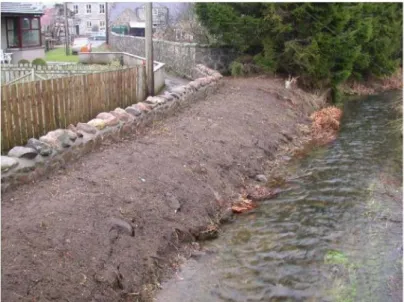
Vegetation removal is likely to destabilise the banks and/or bed of the watercourse or make them more vulnerable to erosion (see Figure 4). Removal of vegetation can also alter flow patterns and induce or accelerate bank or bed erosion. It is vital to take measures to ensure the stability of the bank, particularly where there is a risk of raised water levels (high flows) until the vegetation is re-established. Biodegradable textiles can be used to protect areas of bare soil; for more information see Section 3.8 and SEPA Good Practice Guide WAT-SG-23, Bank Protection: Rivers and Lochs
(http://www.sepa.org.uk/regulations/water/engineering/engineering-guidance/).
Figure 4
X
Poor practice: vegetation cleared and bare soil exposed to allow construction of floodwall leaving risk of bank erosion during a high flow event and rainfall run-off causingSources of further information on good practice in site clearance
SEPA publications: http://www.sepa.org.uk/regulations/water/engineering/engineering-guidance
•Riparian Vegetation Management (WAT-SG-44). • /Bank Protection: Rivers and Lochs (WAT-SG-23).
• /On-site Management of Japanese Knotweed and Associated Contaminated Soils, Technical Guidance Note,
Version
http://www.sepa.org.uk/media/154142/onsite_mangaement_of_-japanese_knotweed_associated_soils.pdf
Other publications:
• Guidance for the Control of Non-native Invasive Weeds In or Near Fresh Water, Environment Agency, 2007. http://publications.environment-agency.gov.uk/pdf/GEHO0307BLZO-e-e.pdf
• Environment Agency facts sheets on invasive species:
www.environment-agency.gov.uk/homeandleisure/wildlife/31350.aspx • BS 5837: 2005 Trees in Relation to Construction – Recommendations.
www.bsi-global.com
3.3 Minimise run-off of contaminated water
As stated in Section 1, this Guide focuses on temporary works required for the construction of engineering activities in river or lochs. It does not cover pollution prevention measures for the whole construction site. This section describes some basic principles but does not go into detail on preventing pollution from the wider construction site as there is already considerable existing guidance on this subject which should be followed (see box below).
As discussed in Section 2, contaminated water can arise from a number of sources including:
• direct disturbance of the river bed or bank; • de-watering of excavations;
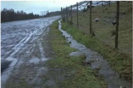
• run-off from exposed ground and material stockpiles (see Figure 5); • run-off from roads and haul routes and river crossings;
• plant washings;
• fuel and chemical storage/refuelling areas; • leaking/vandalised equipment.
The risk of water becoming polluted in the first place should be minimised. All sources of pollution should be identified at the planning stage (see Section 3.1) and appropriate mitigation measures put in place.
Figure 5
X
Poor practice: topsoil from excavations stockpiled beside river leaving risk of pollution from run-off or high flowLocate areas of high risk away from watercourses and drainage paths. Areas of high risk include:
• fuel and chemical storage; • refuelling areas;
• material stockpiles;
• vehicle and equipment washing areas; • site compounds/parking areas.
Store fuel, oils and chemicals on an impervious base within a bund able to contain at least 110% of the volume stored.
If possible use biodegradable oil in plant and machinery. Biodegradable oil is less toxic than most synthetic oil but should still be used and stored to the same standards as other oils.
Oil must be stored in accordance with the Water Environment (Oil Storage) (Scotland) Regulations 2006. The Regulations apply to any kind of oil including petrol, diesel, mineral oil, heating oil, lubricating oil, waste oil, vegetable and plant oil. More information on these regulations and when they apply can be found on the SEPA website ( http://www.sepa.org.uk/regulations/water/pollution-control/scottish-oil-storage-regulations/
There are three simple principles which should be followed to minimise the volume of contaminated run-off being generated.
• DIVERT clean water away from exposed soils and working areas. • MINIMISE erosion of exposed soils.
• PREVENT contaminated water from entering watercourses untreated.
The selection of control measures will depend on how effective they will be on a site-by-site basis. The effectiveness of control measures will depend on weather, site characteristics and construction activities. It is important that the selected control measures are inspected regularly – and particularly after rainfall – to assess:
• effectiveness;
• the need for maintenance or replacement with alternative measures.
DIVERT clean surface water away from exposed soils
This can significantly reduce the volume of water contaminated with sediment on site thus reducing the risk of pollution and the costs associated with treating contaminated water before discharge.
• Diversion drains. Such diversion can be implemented on the upstream perimeter of the site or immediately upstream of areas of exposed soil on the site (eg excavations, embankments and stockpiles). Line drains with a non-erodible material such as turf/geotextiles.
• Bunds. These can be placed around exposed soils such as excavations/material stockpiles. This will prevent clean water entering the area and dirty water from leaving the area. Bunds should be made of non-erodible material such as straw bales/geotextiles.
Route uncontaminated water to nearby land or surface water. MINIMISE erosion of exposed soils
The most obvious way to minimise erosion is to minimise the amount of soil exposed. Existing mature vegetation will not only be able to absorb rainfall and filter sediment polluted run-off, but the extensive root systems help to hold soils together and reduce erosion.
Leave as much existing vegetation in place as possible and protect it with fences and signs where necessary. Only clear that part of the site which will be worked on in the near future. Consider phasing site clearance for different stages of the work.
Leave buffer strips of vegetation 5–10m wide along site boundaries and river banks to act as sediment filters. Buffer strips are generally secondary measures and must not be used as the sole method to prevent or treat the escape of polluted water.
Where it is necessary to remove vegetation and it will not to be replaced by permanent works, establish new/replacement vegetation (using seeds from a local and reputable source) as soon as practicable. Until vegetation is fully re-established, temporary protection of the soil may be necessary (see below). For further guidance on establishing vegetation
see SEPA Good Practice Guide WAT-SG-44, Riparian Vegetation Management (http://www.sepa.org.uk/regulations/water/engineering/).
Where exposed soil is to be left for a long period of time before completion of the works or before seeding or planting can be established, other measures to prevent soil erosion may be required. This can include the use of:
• Geotextiles (biodegradable and non-biodegraable); • mulching/binders/hydroseeding;
• turf cut from other areas on site where vegetation is being removed (can be reused elsewhere for permanent reinstatement as required);
• surface roughening/benching
PREVENT water polluted with sediment from leaving the site
There are many techniques and existing guidance to help minimise the mobilisation and loss of sediments/silt into waters. In certain circumstances it may be impossible or prohibitively expensive to prevent erosion of exposed soils. In such circumstances it is necessary to ensure that:
• water polluted by sediment is not allowed to leave the site untreated;
• the level of treatment is sufficient to ensure the final discharge is acceptable.
In most cases this will involve collecting the polluted run-off and routing it to treatment by filtration, settlement or specialist techniques (see Section 3.6). As well as treatment immediately prior to discharge, polluted water can be treated at source and en route to the discharge point – though this does not necessarily negate the need for further treatment before discharge. Widely used techniques include:
• diversion drains/ditches (see Figure 6); • silt fence;
• fibre roll; • filter bund; • silt trap;
• haul routes and site entrances; • surface drainage protection.
Figure 6 Good practice: diversion ditch along access road to intercept polluted water and carry to a treatment area
Haul routes, access roads and parking areas can generate significant quantities of water polluted with sediment. Being temporary in nature, they are often formed by simply stripping topsoil and grading the subsoil to suit. This means that during heavy rainfall surface run-off can erode the surface. The tracking of plant and machinery across wet or saturated soil can also loosen and mobilise additional sediment.
• Consider applying binder to road surfaces. This will also help to reduce dust pollution during dry weather.
• Shed water from roads onto adjacent vegetation or construct ditches along the road edge(s) to prevent uncontaminated run-off flowing onto the road and to direct contaminated run-off to treatment facilities. Do not allow roadside ditches to discharge directly to rivers, burns, lochs or wetlands.
• Prevent excess water running along the road by installing small earth bunds (like speed bumps) or cut-off ditches (see Figure 7) at regular spacing to direct water into roadside ditches.
Where haul routes cross watercourses, adopt measures to prevent sediment-laden run-off from entering them. This can be done by:
• Ensuring crossing structures have edge upstands or bunds eg straw bales, sandbags or earth;
• making sure bridge decks are sealed (see Section 3.7).
Where inlets to existing surface water drainage are present on- site (eg road gullies or yard drains), protect them from run-off polluted with sediment. This is best done by diverting the water away from the inlet to treatment facilities. Where this is not possible, create a bund around the surface water drain to prevent contaminated water entering.
Figure 7 Good practice: cut-off drain on haul route to prevent erosion and direct polluted surface water to diversion drains or treatment areas (photo courtesy of Scottish and Southern Energy)
Guidance on preventing pollution from construction sites CIRIA publications – available from https://www.ciria.org/
• Control of Water Pollution from Construction Sites – Guide to Good Practice (SP156)
• Control of Water Pollution from Construction Sites – Guidance for Consultants and Contractors (C532)
• Control of Water Pollution from Linear Construction Projects – Technical Guidance (C648)
• Control of Water Pollution from Linear Construction Projects – Site Guide (C649)
• Environmental Good Practice – Site Guide (C650) • The SUDS Manual (C697)
• Site Handbook for the Construction of SUDS (C698)
Pollution prevention guidance published jointly by Environment Agency, SEPA and Environment and Heritage Service:
• Getting Your Site Right. Industrial and Commercial Pollution Prevention.
www.environment-agency.gov.uk/static/documents/Business/pp_pays_booklet_e_1212832.pdf • PPG5: Works and Maintenance In or Near Water
• PPG6: Working at Construction and Demolition Sites
PPGs are available from the NetRegs website (www.environment-agency.gov.uk/netregs/links/63893.aspx).
3.4 Isolation of works area
Where engineering works are carried out in or on the banks of rivers, burns, ditches, lochs and wetlands, it is often necessary to isolate and de-water the work area to create dry working conditions. Isolation of the works area reduces the risk of sediment entering the river or loch.
The first and most important consideration is whether it is possible to design out the need for such temporary works. This can be achieved by:
• considering alternative permanent works that do not encroach on the channel, loch or wetland (eg set back bridge abutments and single span bridges);
• using alternative construction methods (eg directional drilling or tunnelling rather than open cut excavation for pipe and cable crossings).
If temporary works in or on the banks of rivers, burns, ditches, lochs or wetlands are unavoidable, choose the isolation method that causes the least disturbance to the water
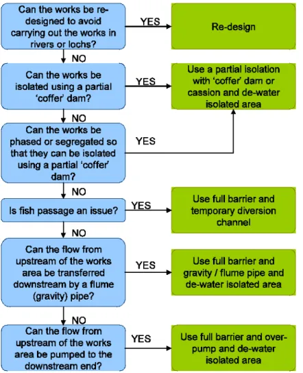
body but provides the highest level of pollution protection. The flow chart shown in Figure 8 will help select an appropriate method of isolation.
As well as initially de-watering the isolated work area, most of the isolation methods are likely to require continual or intermittent de-watering due to ingress of surface water, seepage or groundwater. Guidance on de-watering can be found in Section 3.5.
Figure 8 Choosing a method for isolating a works area in rivers or lochs
Figures 9 to 14 summarise the different isolation methods. The following sections present good practice guidance for the various methods.
Figure 9 Good practice: partial isolation/‘cofferdam’
Partial area of the channel is isolated and kept dry with the use of barriers (often referred to as a cofferdam) and flow is allowed to continue in the remainder of the channel. Barriers used to isolate part of the channel can be made of a number of different materials.
Figure 10 Good practice: partial isolation using a Caisson provides isolation of the channel similar to cofferdams. They are essentially large boxes or cylinders (usually pre-cast concrete and steel) which are open at the top and bottom and are lowered into the water to isolate an area of bed.
Figure 11 Good practice: full isolation temporary diversion channel
A whole section of the channel is isolated and kept dry, and the water is transferred downstream of the works area by excavating a temporary open channel.
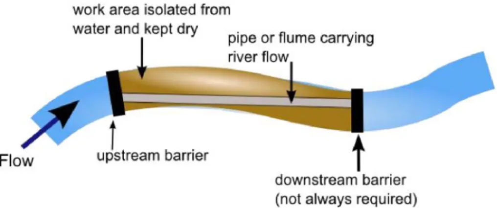
Figure 12 Good practice: full isolation gravity/flume pipe
A whole section of the channel is isolated using barriers that span the full width of the river. This keeps a stretch of the river dry and the water is transferred downstream of the works area through gravity fed flumes/pipes. The flume(s) is normally placed on the bed of the watercourse through the works area and outfalls at the downstream barrier, if present, or far enough
Figure 13 Good practice: full isolation over pumping / siphon
A whole section of the channel is isolated using barriers that span the full width of the river. This keeps a stretch of the river dry and the water is transferred downstream of the works area by mechanical assistance (pumping or siphon). The pump and associated pipework need not be located in the isolated area.
Figure 14 Good practice: isolation with silt curtain
In this case the works area still remains wet and a silt curtain is placed around the works area to minimise sediment being transferred downstream.
Partial isolation using a cofferdam
Figure 15 Good practice: steel piled cofferdam
A variety of methods using different materials are available to create temporary cofferdams: • sandbag barriers;
• specialist dam structures on the river or loch bed (water filled membrane or steel, timber and concrete frame with impervious membrane);
• gravel, clay or earth bunds;
• steel, timber, concrete or plastic piled cofferdams;
A number of factors affect the choice of cofferdam material including: • depth of water;
• available space; • duration of works; • bed conditions; • accessibility;
• potential ingress of water.
Before choosing which method and material to use, it is also important to consider its potential impact on the water environment. The choice of material will depend on the conditions at a specific site.
The cofferdam must be designed by a competent person. The design should take into account:
• the reduction in channel capacity (for flood risk);
• the potential increase in flow velocity (for adjacent bed and bank erosion and toe scour);
• changes in flow patterns (for adjacent bed and bank erosion and toe scour); • fluctuations in water level (for adequate freeboard);
• alignment of the cofferdam, particularly at the upstream and downstream ends where bank erosion can be induced.
When determining the height of the barrier, make allowance for potential fluctuations in water levels (freeboard). Monitor the weather forecast and expected flows/water levels throughout the works and have a contingency plan in place to prevent damage or pollution during extreme weather and high flow events.
Inspect the barrier daily for movement, leakage and general deterioration. Take immediate remedial action to rectify any defects.
The work area must never be de-watered directly into any adjacent surface water. The removed water must receive treatment before discharge. See Section 3.5 for more guidance on de-watering.
After de-watering but before commencement of works, carefully remove the exposed bed material from areas which will be disturbed (particularly where plant will be operating) and stockpile it, to be used for reinstatement. Protect the stockpile from pollution or contamination. Note the elevation and distribution of the existing bed carefully and, if necessary, carry out a survey to ensure the bed profile can be reinstated after works using the original bed material where possible (see Section 3.8).
When the works are complete but before the barrier is removed, ensure all materials, debris, tools, plant and equipment are removed from the work area. Check the area thoroughly for spillages or potential pollution sources. Remove or clean up anything found.
Re-water the work area before removing the cofferdam to avoid sudden ingress of water causing erosion of the replaced bed or bank material. When re-watering, screen the pump inlets to prevent intake of fish or other aquatic animals.
Table 1. Cofferdam barrier materials S an d ba g b ar ri er s
Advantages: Disadvantages: Woven polypropylene bags are less likely Inexpensive Only suitable for relatively to burst than hessian. They can be reused Materials are readily shallow water and small- and give greater control over leakage of available. scale works. the fill material. The fill material should be Quick installation and Labour intensive dense and homogenous (typically course removal for small-scale installation and removal. grain sand).
works. Sandbags can rupture The bags should be well compacted and Minimal disturbance to releasing sediment into knit together to take up gaps between
bed. the water. bags.
Can easily be shaped Prone to leakage. Place a geotextile filter or impermeable layer to tie in to banks Large footprint required on the retained water side of the barrier to
for deeper water. prevent seepage of silt through the barrier into the water. Ensure this layer is well- anchored along the base of the barrier and extends above the water line, where it should also be well secured.
S pec ial is t d am s tr uc tur es
Advantages: Disadvantages: There are several different proprietary dam Minimal disturbance to Restriction on retained systems available from different suppliers. bed. water height These include steel framed structures with Some systems can be (approximate maximum impermeable membranes and water filled reused at other projects 2–3m). membranes (Contact SEPA if water for or locations. Some systems are limited water-filled structures is to be taken from Good seal achievable by flow velocity. rivers, burns, lochs or wetlands).Advice limiting the need for de- Can be susceptible to should be sought from a suitably qualified watering of the working movement or breach person for assistance with the design. area. during flood flows.
E
ar
th B
u
nds
Advantages: Disadvantages: Gravel, clay and earth bunds have risk of Quick to install and Susceptible to washout of causing sediments to pollute the water remove. fine grain material and environment. When used, special Good seal achievable erosion from passing precautions must be taken to prevent with clay limiting the flow. damage to the bed and release of sediment need for de-watering of Susceptible to leakage from the bund.
the working area. when sands or gravels A silt curtain or similar silt containment Can be used on are used. method (see below for further information) uneven beds. Washout due to leakage should be installed before the bund and Can be installed from can also significantly must remain in place until after the bund is bankside using weaken the bund leading removed. For shallow water depths mechanical plant. to sudden failure. consider lining the waterside face of the
Damage/disruption to bed bund with geotextile to prevent washout. during installation and Consider placing a geotextile or other removal. durable material on the bed directly under
the bund to help prevent damage to the bed during installation and removal.
P iled c o ff er d ams
Advantages: Disadvantages: Piled cofferdams are normally used for Can be used in fast Specialist plant required construction in deeper or particularly fast flowing or deep water. for installation and flowing water and / or where excavation Minimal damage to bed removal. below bed level is required for construction during installation and Susceptible to leakage of the permanent works. Although it is removal. through pile joints. possible to use timber and pre-cast concrete Minimal space required Vibration and noise piles to construct cofferdams in water, the outside of minimum during installation. most common choice of material is steel work area (if single line Subsurface obstructions sheet piles (see Figure 15). Plastic piles are can be used). (big boulders) can cause also available.
Can be installed from installation problems. Piles can be placed in a single line or double bankside. Banks may need to
be modified to create the upstream and downstream returns of the cofferdam.
skin with an earth fill between the skins.
Source of further information on sheet-piled cofferdams
• The Design and Construction of Sheet-piled Cofferdams, SP095M,
CIRIA, https://www.ciria.org/
Partial isolation using Caissons
Caissons offer partial isolation of the channel similar to cofferdams. They are essentially large boxes or cylinders (usually pre-cast concrete and steel) which are open at the top and bottom and are lowered into the water to isolate an area of bed (see Figure 16). The caisson can then be de-watered. The bed can also be excavated to create a working space below bed level. The caisson may also have an ‘air deck’ installed so that the compartment below the deck can be de-watered and filled with compressed air (similar to a diving bell) to prevent ingress of water and allowing working in the dry. The caisson can be used as part of the permanent works, eg permanent shuttering for bridge foundations. Caissons are generally only used for construction in deep water. It should be ensured that the caisson is free from dirt, dust, grease, oil or other chemicals when it is installed.
Advantages Disadvantages
Can be used in deep water Expensive
Minimal damage to bed during installation Access to working area can be difficult. Can be used as part of the permanent works
Can be made watertight.
Full isolation using a gravity/flume pipe
Figure 17 Good practice: sandbag barrier and gravity fed pipe (photo courtesy of Scottish and Southern Energy) and Figure 18 Good practice: full isolation of channel by
gravity flume
Where it is necessary to isolate and keep dry an entire reach of river, burn or ditch, a barrier will need to be constructed across the full width of the watercourse upstream of the works area. In the vast majority of cases it will be necessary to transfer water from upstream of this barrier to downstream of the works area, ie maintain ‘normal’ flow in the watercourse either side of the isolated reach. Figure 17 and 18 show water transferred downstream with the use of a gravity fed pipe, ie there is no requirement for pumps to be used. Depending on the gradient of the watercourse, it may also be necessary to install a full width barrier downstream of the work area to prevent ingress of water. The methods available for creating full width barriers are largely the same as given in Table 1 above for partial barriers (cofferdams).
Advantages Disadvantages Works by gravity (no pump required, reduces
risk of equipment failing).
Causes a restriction within the working area. Maintains some continuity in watercourse
where passage of aquatic animals and fish is possible
Susceptible to blockage by trash at upstream end
Potentially high flow velocities and turbulence at the flume outlet.
Amount of water transferred is limited to the capacity of the flume. This limits the flow regime in which this technique can be used, ie a relatively predictable constant flow
May need standby pumps Increased flood risk.
The flume pipe must be designed by a competent person. The design should take into account the following aspects.
Flood risk
The nature of this type of isolation work means that the risk of flooding – particularly upstream – can be significantly higher. Great care needs to be taken with the design of the barriers and water transfer system and a carefully considered monitoring and contingency plan must be in place. This technique may therefore only be suitable for watercourses with low flows.
• Ensure measures are in place to deal with high flow situations and that the flood risk to surrounding property is not increased.
• Monitor the weather forecast and expected flows/water levels throughout the works. • Put in place a contingency plan to prevent unplanned inundation of the work area
during high flows, eg making the works secure and removing the flume pipe and barriers if high flows are expected.
Flow and erosion
There is a need to achieve a ‘balancing’ flow so that the alteration to upstream and downstream water levels is minimal. Put in place measures to dissipate energy at the downstream end of the pipe or pump to prevent bed or bank scour at the outlet.
Fish passage and wildlife issues
Programme the works to minimise disruption to the free passage of fish and aquatic animals. The most acceptable timing will depend on which sensitive species are present and should be agreed with SEPA, Scottish Natural Heritage (SNH) and the local District Salmon Fisheries Board.
• Keep the duration of the isolation works as short as possible. • Screen the intake to prevent fish being drawn into the flume/pipe.
• Before the isolated area is de-watered, take appropriate measures to relocate any stranded wildlife. Consult SNH to establish relocation requirements.
• Ensure specialist techniques such as electro-fishing are carried out by suitably qualified personnel.
• Consider transplanting or watering sensitive aquatic vegetation in the isolated area if there is a risk that it will be damaged due to the removal of water.
Debris accumulation
To minimise trash and sediment accumulation at the upstream end, inspect the flume pipe (including the inlet and outlet) regularly for damage or blockage. Clear blockages and repair any damage immediately.
Flume/pipe condition Leaks should be minimised.
• Inspect the flume pipe (including the inlet and outlet) regularly for damage, paying particular attention to joins and seals.
• Protect the flume pipe from crushing or impact damage. This may include:
− aligning it away from plant movement and areas where work will be carried out; − using temporary barriers or protective covers.
Removal
Before removing the upstream barrier, remove any accumulation of silt or trash against the barrier and dispose of it appropriately. If a downstream barrier is present, remove this first. Full isolation – over pumping/siphon
Figure 19 Good practice: full isolation of channel by over pumping
In some cases it will be necessary to pump water (Figure 19) from upstream of the barrier to downstream of the works area, ie maintain ‘normal’ flow in the watercourse either side of the
methods available for creating full width barriers are largely the same as given above for partial barriers (cofferdams).
Advantages Disadvantages
Pump and pipework can be kept out of the work area
Standby pumps are required in case of breakdown.
Aquatic animals and fish can be harmed by being drawn into the pump(s).
Potentially high flow velocities and turbulence at the downstream outlet introduces a discontinuity in the watercourse preventing the free passage of aquatic animals and fish.
Alterations to local flow patterns cause induced or accelerated bed and bank erosion, or sediment deposition or increased flood risk.
Prevention of free passage and potential harm to fish and aquatic animals.
Disruption to aquatic and riparian animals due to continuous noise and vibration from pump(s).
The size and type of pumps must be determined by a competent person and may require consultation with the pump manufacturers. The design should take into account the following aspects.
Flood risk
The nature of this type of isolation work means that the risk of flooding – particularly upstream – can be significantly higher. Great care needs to be taken with the design of the barriers and water transfer system and a carefully considered monitoring and contingency plan must be in place. This technique may only be suitable for watercourses with low flows.
• Ensure measures are in place to deal with high flow situations and that the flood risk to surrounding property is not increased.
• Monitor the weather forecast and expected flows/water levels throughout the works. • Put in place a contingency plan to prevent unplanned inundation of the work area
during high flows, eg making the works secure and removing the flume pipe and barriers if high flows are expected.
Flow and erosion
There is a need to achieve a ‘balancing’ flow so that the alteration to upstream and downstream water levels is minimal. If pumping, consider variable flow rate pumps.
Ensure pump outfalls and outfalls from any temporary treatment do not cause or generate erosion of the banks or bed. This can be done by using baffles or other energy dissipating devices and scour protection. Much of the guidance given for permanent outfalls can also
be applied to temporary outfalls (see SEPA Good Practice Guide WAT-SG-28, Intakes and Outfalls; http://www.sepa.org.uk/regulations/water/engineering/).
Debris accumulation
If pumps are used, accumulation of sediment/trash at the upstream end may affect pump performance and/or be transferred downstream with the pumped water.
• Inspect pipe/pump intakes regularly for blockages and clear immediately.
• Put in place measures to dissipate energy at the downstream end of the pipe/pump to prevent bed or bank scour at the outlet.
Fish passage and wildlife issues
Programme the works to minimise disruption to the free passage of fish and aquatic animals. The most acceptable timing will depend upon which sensitive species are present and should be agreed with SEPA, SNH and the local District Salmon Fisheries Board.
• Keep the duration of the isolation works as short as possible. • Screen the intake to prevent fish being drawn into the pipe/pump.
• Before the isolated area is de-watered, take appropriate measures to relocate any stranded wildlife. Consult SNH to establish relocation requirements.
• Ensure specialist techniques such as electro-fishing are carried out by suitably qualified personnel.
• Consider transplanting or watering sensitive aquatic vegetation in the isolated area if there is a risk that it will be damaged due to the removal of water
Pipe/pump condition
Where pumps are used, make a competent person responsible for regularly monitoring the over pumping including:
• upstream and downstream water levels; • flow rate;
• pump performance; • inlet(s) and outlet(s); • fuel level(s).
Minimise leaks from the pipework.
• Inspect the pipework (including the inlet and outlet) regularly for damage, paying particular attention to joins and seals.
• Protect the pipework from crushing or impact damage. This may include:
− aligning it away from plant movement and areas where work will be carried out; − using temporary barriers or protective covers.
Removal
Before removing the upstream barrier, remove any accumulation of silt or trash against the barrier and dispose of it appropriately. If a downstream barrier is present, remove this first.
Pump operation
Ensure that any pumps and associated pipework used are emptied, thoroughly cleaned and dried before leaving the previous site, to minimise the risk of transferring water containing plant or animal diseases, or invasive non-native species, to the development site. On completion of work, all pumping equipment should be emptied, thoroughly cleaned (and preferably dried) before leaving site in order to prevent moving anything damaging to the next site at which it is to be used.
Pumping operations should avoid placing the inlet pipe amongst water plants and the pump inlet should be positioned just below the water’s surface, rather than on the bed of the water body, to reduce the risk of non-native plant or animal species being taken through the pump. Position standby pump(s) at the site of over pumping ready to be deployed if the main pump(s) fail. Test these standby pump(s) regularly. If the standby pump(s) are used to replace the failed main pump(s), bring additional standby pump(s) onto site.
Keep the pump(s) at least 10m from the edge of the channel and on drip trays or within bunds that have a capacity 110% of that of the fuel tank.
Suspend the inlet to the pump above the bed of the channel to avoid mobilisation of settled silt and sediment from the bed. The inlet could be suspended from an excavator arm or temporary support spanning the channel.
Screen the inlet to avoid intake of aquatic animals and check it regularly for blockages. Avoid over pumping overnight or between shifts. Schedule the work so that there is 24-hour supervision of the over pumping or re-water the isolated area at the end of each day/shift. If re-watering is chosen, the design of the barriers must allow for continuity of flow through the isolated area while it is re-watered. Leave any works carried out in the isolated area between periods of re-watering in a state that will not cause erosion or displacement of the works, bed or banks.
Consider using a siphon system as an alternative to mechanical pumping. This will require: • mechanical pumping to prime the siphon;
• a method for controlling the flow rate, eg a throttle or multiple siphon pipes.
Full isolation – temporary diversion channel
Figure 20 Full isolation by temporary diversion (NB The geotextile lining should extend to the full bank height and be properly secured.)
This method (see Figure 20) may also be more suitable for longer term isolation although in all cases works in the water must be kept to absolute minimum.
Advantages Disadvantages
required. at the start and end of the diversion Less risk of accidental inundation of isolated area
than flume pipe(s) or over pumping.
Potential for silt being mobilised diversion channel.
from the Passage for fish and aquatic animals can be
maintained.
It is essential that:
• the diversion channel is designed by a competent person with appropriate experience;
• a drawing of the diversion is produced showing plan views and cross-sections at regular intervals together with a longitudinal section;
• there is a specification for all materials used and a method statement describing the formation, use and reinstatement of the channel.
The design should take into account the following aspects. Flood risk
This arises as a result of the hydrology of the watercourse and the potential for fluctuations in flow during the isolation works.
Make allowance for dealing with high flows particularly for long duration diversions. Justification for the chosen value of maximum flow will be required. Decide the chosen value by assessing the risk of high flows during the diversion. This value should take into account factors such as:
• the length of time the diversion will be in place; • the time of year the diversion is in place; • historical rainfall patterns for the catchment; • historical flow data (where available);
• the effects of diversion channel overtopping.
Channel dimensions and design
• Hydraulics and morphology of the existing channel (eg gradient, water depth and velocity, channel cross-section and alignment, sediment transport and bed material). These should be replicated where possible in the diversion channel. The degree to which this is done will depend on the duration of the diversion, ie for longer duration diversions more effort must be made to replicate the existing channel. As a minimum, maintain the existing channel width and water depth (within reason) through the diversion channel.
• Potential bank and bed erosion at the start and end of the diversion. As noted above, every effort should be made to replicate existing bank conditions where possible. As general guidance, the bank slope should not be steeper than 1 in 2; this should be viewed in the context of the most geomorphologically suitable channel cross-section and plan form.
Excavate the diversion channel in isolation from the watercourse, retaining ‘plugs’ at the upstream and downstream end until it is completed. Remove the downstream plug first and then the upstream plug.
Stockpile material excavated during formation of the diversion channel away from the channel edges to prevent sediment run-off during rainfall or high flows. Alternatively, protect stockpiles along the channel adequately to prevent sediment run-off.
Lining of channel
Line the excavated diversion channel before water is diverted into it to prevent mobilisation of silt and sediment. The lining should normally include a geotextile but, depending on hydraulics, may also be turf, vegetated matting, gravel/cobbles/boulders or a combination of these. Where geotextile is used, one piece should cover the whole channel where possible. Where this is not possible, place strips perpendicular to the flow with minimum 600mm overlaps (upstream piece overlapping downstream). Use gravel and riprap to hold the geotextile in place both on the bed and buried in trenches at the top of the banks. Bury the upstream end of the geotextile into a 600 × 600mm trench in the bed of the diversion channel.
Best practice is normally to line the bed of the diversion channel with suitably sized sediment similar to that in the isolated reach. This may not be necessary for very short duration diversions (eg those in place for only a couple of days) but would need to be justified on a case-by-case basis.
Careful design is required to ensure that the existing sediment transport regime is replicated as far as possible (ie it is important to ensure there is no significant increase in deposition along the diverted reach nor that sediment input from upstream is transported at a significantly increased rate through the diversion) as this could lead to significant geomorphological changes upstream and downstream. This will require the input of a suitably qualified person with relevant geomorphological experience. Include natural formations such as pools and riffles where appropriate.
Fish passage and wildlife issues
Programme the works to minimise disruption to the free passage of fish and aquatic animals. The most acceptable timing will depend on which sensitive species are present and should be agreed with SEPA, SNH and the local District Salmon Fisheries Board.
• Keep the duration of the isolation works as short as possible. • Screen the intake to prevent fish being drawn into the flume/pipe.
• Before the isolated area is de-watered, take appropriate measures to relocate any stranded wildlife. Consult SNH to establish relocation requirements.
• Ensure specialist techniques such as electro-fishing are carried out by suitably qualified personnel.
• Undertake any in-stream wildlife relocation as the upstream and downstream (where used) barriers are put in place.
Make a competent person responsible for monitoring the diversion channel at regular time intervals. This should include:
• water levels (upstream, downstream and in the diversion); • bank and bed erosion at the upstream and downstream ends; • channel stability;
• trash accumulations.
Any problems should be communicated to the designer who should agree remedial works or alterations with SEPA.
Look out for debris and sediment accumulation in the diversion channel. Isolation with silt curtain
This method should be used only in slow flowing water (lochs, large rivers) where no other isolation method to allow working in the dry is possible.
Make provision for removing the silt from behind the curtain before removing the curtain.
3.5 De-watering of isolated area
Isolated work areas and excavations must never be de-watered directly into adjacent or nearby rivers, burns, ditches, lochs or wetlands
De-watering is usually be carried out by mechanical pumping. It can involve:
• the initial removal of water from the isolated area behind a temporary barrier;
• ongoing removal of water from behind cofferdams, temporary barriers or excavations.
All discharges from de-watering must receive an appropriate level of treatment before discharge. Assess the pollutants likely to be present to identify the type of treatment required (see Section 3.6).
Under Controlled Activities Regulations, the discharge of water from any
de-watering treatment must comply with General Binding Rule (GBR) 10 Discharge of Water Run-off. For more information, see the CAR Practical Guide available from the SEPA website (http://www.sepa.org.uk/regulations/water/engineering/).
Dewatering to enable working within a river does not require an authorisation for the abstraction of water under the Controlled Activities Regulations.
Adopt measures to minimise the ingress of water to the excavation or isolated area. This may include:
• ensuring cofferdams and barriers are well sealed;
Deep excavations may require specialist techniques such as cut-off walls or grouting to control the ingress of groundwater. SEPA must be consulted where this is proposed.
The use of submersible pumps, in particular, can mobilise silt into suspension through turbulence at or near the inlet. Where submersible pumps are used, place them in a sump that isolates them from the base of the excavation, eg on a gravel base inside a large diameter perforated pipe or manhole ring (see Figures 21 and 22) or suspended above the base of the excavation.
Figure 21 Good practice: typical submersible pump sump showing gravel base and perforated container and Figure 22 Good practice: pump intake located in a perforated barrel (photo courtesy of Scottish and Southern Energy)
Avoid using excavator buckets to de-water unless it is from an excavation away from a river, burn, ditch, loch or wetland and the water is discharged to nearby land or a constructed basin for treatment by filtration or settlement respectively (see Section 3.6).
Where pumps are used, ensure they are the correct size and type for volumes of water expected. Check the pump(s) and hose(s) regularly for leaks. Uncontrolled leakage can cause additional surface water run-off problems.
Ensure that pump outfalls and outfalls from any temporary treatment do not cause or generate erosion of land, banks or beds. This can be done by using baffles or other energy dissipating devices and scour protection. Much of the guidance given for permanent outfalls can also be applied to temporary outfalls (see SEPA Good Practice Guide WAT-SG-28,
Under the Controlled Activities Regulations and General Binding Rule (GBR) 10, discharges of run-off water from construction sites are required to be treated by a Sustainable Urban Drainage System (SUDS) or equivalent. For more information see the CAR Practical Guide available from the SEPA website (http://www.sepa.org.uk/regulations/water/).
Contaminated water must be dealt with in accordance with the relevant waste regulations including:
• Environmental Protection Act 1990;
• Controlled Waste Regulations 1992 (as amended); • Special Waste Regulations 1996 (as amended);
• Waste Management Licensing Regulations 1994 (as amended).
3.6 Treatment and/or disposal of contaminated water
As stated in Section 1, this Guide focuses on temporary works required for the construction of engineering activities in river or lochs. It does not cover pollution prevention measures for the whole construction site. This section describes some basic principles but does not go into detail on the treatment and disposal of contaminated water from the wider construction site as there is already considerable existing guidance on this subject which should be followed (see box on sources of further information at the end of this section).
All potential sources of pollution should be identified at the planning stage and appropriate treatment or disposal methods decided.
At the pre-planning/planning stages of construction projects, consider the use of SUDS as means of treating surface water from the completed structure (where appropriate). Where SUDS are to be included as a permanent feature (eg ponds or wetlands) it should be possible to make use of the area designated for the SUDS to deal with contaminated run-off from the building site.
Avoid and minimise the generation of contaminated water as described in Section 3.3. As discussed in Section 2, contaminated water can arise from a number of sources including:
• direct disturbance of the river bed or bank; • de-watering of excavations;
• run-off from exposed ground and material stockpiles; • run-off from roads and haul routes and river crossings; • plant washings;
• fuel and chemical storage/refuelling areas; • leaking/vandalised equipment.
Appropriate treatment or disposal options will depend on a number of factors including: • volume of water;
• type of pollutant;
• area of land available for treatment/discharge; • amount and type of silt.
A combination of treatment and disposal methods is likely to be required. Treatment and disposal methods include:
• discharge to sewer; • tanker off-site;
• sustainable drainage systems (SUDS); • disposal of water off-site;
• settlement lagoons;
• filtration including mechanical filtration; • infiltration/pump to grassland.
Discharge to foul sewer
Contaminated water can be pumped or drained to the public sewer. Permission to discharge to the public sewer must be obtained from Scottish Water (www.scottishwater.co.uk).
Tanker off-site
Water can be stored on-site, then pumped into tankers and taken away for disposal elsewhere at appropriately authorised off-site facilities.
Sustainable drainage systems
SUDS is the practice of controlling surface water run-off as close to its origin as possible by slowing flows, allowing adequate settlement and in certain cases some biological action to take place before water is discharged.
Under General Binding Rule (GBR) 10 of the Controlled Activities Regulations, discharges of run-off water from construction sites are required to be treated by a Sustainable Urban Drainage System (SUDS) or equivalent.
Settlement ponds and tanks
To remove sediment from water by settlement, the water needs to be retained in an undisturbed state (ie not moving) for a period of time. This allows particles to fall out of suspension. The rate at which they fall out depends on size, with finer particles taking longer to settle. Also, the deeper the water the longer it will take for particles to settle. Other factors affecting settlement include temperature, particle density and water disturbance.
Settlement ponds and tanks must be large enough to allow retention for sufficient time for the particles to settle. This may require the use of ponds or tanks in series (see Figures 23
If the use of flocculants is proposed, contact SEPA in advance to discuss any risks as these agents can be polluting/toxic.
Figure 24 Good practice: settlement tanks (photo courtesy of Scottish and Southern Energy)
Filtration
Limited volumes of contaminated water can be passed through a filter medium to remove sediment. Suitable filtration media can include straw bales, single sized aggregate (5–-10mm) or geotextiles. Mechanical filtration units can also be used and are available from a number of different suppliers. These can be used in single units or joined together for larger volumes.
Infiltration/pump to grassland
The suitability of this method depends on a number of factors including: • gradient of ground;
• type of vegetation and soil;
• condition of ground (the method is not effective if the ground is saturated due to wet weather).
Guidance on treatment/disposal of contaminated water from construction sites
CIRIA publications – available from https://www.ciria.org/ • The SUDS Manual (C697)
• Site Handbook for the Construction of SUDS (C698
• Control of Water Pollution from Construction Sites – Guide to Good Practice (SP156)
• Control of Water Pollution from Construction Sites – Guidance for Consultants and Contractors (C532)
• Control of Water Pollution from Linear Construction Projects – Technical Guidance (C648)
• Control of Water Pollution from Linear Construction Projects – Site Gguide C649)
• Environmental Good Practice – Site Guide (C650)
Pollution prevention guidance published jointly by Environment Agency, SEPA and Environment and Heritage Service:
• Getting Your Site Right. Industrial and Commercial Pollution Prevention.
www.environment-agency.gov.uk/static/documents/Business/pp_pays_booklet_e_1212832.pdf • PPG5: Works and Maintenance In or Near Water.
PPGs are available from the NetRegs website (www.environment-agency.gov.uk/netregs/links/63893.aspx).
3.7 Temporary river crossings
The same principles of good practice apply to permanent and temporary river crossings. Refer to SEPA Good Practice Guide WAT-SG-25, Construction of River Crossings (http://www.sepa.org.uk/regulations/water/engineering/) for more detailed guidance.
The first thing to consider is whether a river crossing is required at all. • Works should be carried out from the banks where possible.
• Where rivers are required to be crossed, existing bridges should be used where possible.
Where there is no existing permanent bridge, a temporary crossing should be constructed. The river should not be forded as this poses a high risk of sediment getting into the river. Provide temporary haul road bridges, etc with splash plates to prevent vehicular traffic from pushing debris over the edge and into waters.