Draft Final Report – Volume 2
to the
N
ATIONAL
C
OOPERATIVE
H
IGHWAY
R
ESEARCH
P
ROGRAM
(NCHRP)
on Project 12-70
Seismic Analysis and Design of Retaining Walls, Buried
Structures, Slopes, and Embankments
Recommended Specifications,
Commentaries, and Example Problems
June 2008
Submitted byCH2M HILL
in cooperation with
Earth Mechanics, Inc. and Parsons Brinckerhoff Inc.
L
IMITEDU
SED
OCUMENTThis Interim Report is furnished only for review by members of the NCHRP project panel and is regarded as fully privileged. Dissemination of information included herein must be approved by the NCHRP.
Contents
Section 1 – Introduction ... 1-1 1.1 Background... 1-1 1.2 LRFD Design Methodology ... 1-2 1.3 Organization of Volume 2 Report ... 1-4 1.3.1 Part 1 – Specifications and Commentaries... 1-4 1.3.2 Part 2 – Example Problems ... 1-5 1.4 Use of Recommended Specifications and Commentaries ... 1-6
1.4.1 General Use ... 1-6 1.4.2 Specific Topics for Further Evaluation ... 1-7 1.5 Limitations... 1-9 Part 1 – Specifications and Commentaries
Section X – Retaining Walls
Section Y – Slopes and Embankments
Section Z – Buried Structures (Culverts and Drainage Pipes) Part 2 – Example Problems
A) Retaining Walls:
− Gravity and Semi-Gravity Walls − Nongravity Cantilever Walls − Anchored Walls
− Mechanically Stabilized Earth (MSE) Walls − Soil Nail Walls
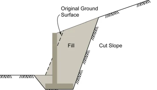
B) Slopes and Embankments − Fill Embankments − Cut Slope
C) Buried Structures − Oval Structure − Box Structure
Section 1 – Introduction
Volume 2 of this Draft Final Report Seismic Analysis and Design of Retaining Walls, Buried
Structures, Slopes and Embankment provides: (1) recommended Specifications and Commentaries for the seismic analysis and design of retaining walls, slopes and embankments, and buried structures; and (2) example problems demonstrating the use of the proposed Specifications and Commentaries. This volume was prepared as part of the National Cooperative Highway Research Program (NCHRP) 12-70 Project. Volume 1 of the Project Report summarizes background information that was used to develop the Specifications, Commentaries, and
Example Problems contained in this volume. The background information in Volume 1 includes a compendium of work summarized in interim Project reports dated January of 2005, March of 2006, and November 2006, and June/July 2007.
1.1 Background
The NCHRP 12-70 Project involved the development of seismic design guidelines in three areas: retaining walls, slopes and embankments, and buried structures. The retaining walls considered in this Project are freestanding walls that do not form part of a bridge structure (e.g., abutment walls are not included). Slopes and embankments can be either natural or fill slopes associated with construction of a new embankment and cuts in existing sloping areas. Buried structures refer to drainage structures and small pedestrian tunnels but not vehicular tunnels.
The Project’s overall objective was to develop analysis and design methods and to prepare LRFD specifications and example problems for the design of retaining walls, slopes and embankments, and buried structures. This overall objective was intended to address short-comings in AASHTO LRFD Bridge Design Specifications being used when the Project was initiated in 2004. In some cases the Project objective addressed the absence of a recommended design methodology in the AASHTO Specifications.
A number of design limitations had been identified within each area of evaluation as summarized below:
• Retaining Walls: Common practice, including the latest edition of the AASHTO LRFD Bridge Design involves use of the Mononobe-Okabe (M-O) equations for estimating seismic active and passive earth pressures. This procedure is found to give unreasonably high levels of earth pressures when some combinations of high ground acceleration and steep backslopes above the retaining wall occur. The M-O equations also are not derived for soil conditions typically encountered during the design of many freestanding walls, and there is general lack of clarity on what seismic coefficient to use in the M-O
equations when assessing the various performance modes (e.g., external and internal stability). Additionally, it is not clear that the M-O equations are applicable for walls that are restrained from movement, such as anchored retaining walls.
• Slopes and Embankments: The AASHTO LRFD Bridge Design Specifications provides no specific guidance for the design of slopes and embankments under gravity or seismic loading. The evaluation of seismic slope stability is often a key component of the earthquake hazards assessment, either when the roadway involves cuts and fills or when global stability poses a risk to a bridge or retaining structure forming part of the transportation corridor.
• Buried Structures: Section 12 of the AASHTO LRFD Bridge Design Specifications provides guidance on the design of culverts and drainage pipes for static loads, but provides no methods for considering seismic loads or seismic-induced ground movement. These buried structures could be damaged by either transient ground displacement (TGD) or permanent ground displacement (PGD) during an earthquake. While many buried structures do not warrant a seismic design, for those situations where the buried structure could lead to damage to the roadway, some standard guidance is needed.
1.2 LRFD Design Methodology
The work carried out for the NCHRP 12-70 Project attempted to be consistent with the philosophy and format of the AASHTO LRFD Bridge Design Specifications and the seismic
provisions for highway bridges. In this philosophy “Bridges shall be designed for specified limit states to achieve the objectives of constructibility, safety, and serviceability, with due regard to issues of inspectibility, economy, and aesthetics….” In the LRFD procedure, margins of safety are incorporated through load (γp) factors and performance (or resistance, φr) factors.
The basic requirement for a project designed in accordance with the LRFD philosophy was to ensure that factored capacity exceeded factored load as defined by the following equation for various limit states (or acceptable performance):
φr Rn ≥ ∑ γi Qi (1-1)
Where
φr = performance factor Rn = nominal resistance
γp = load factor for load component i Qi = load effect due to load component i
For the static (or gravity) design case the appropriate load and resistance factors had been developed for many structures to yield a consistent margin of safety in the designed structure. Ideally, this same logic needed to be followed for seismic loading to retaining walls, slopes and embankments, and buried structures. However, the approach for defining a consistent margin of safety during seismic loading was more difficult to define for the following reasons:
• The load factors and load cases (i.e., on the right-hand-side of the above equation) needed to be consistent with those recommended by the NCHRP Project 20-07 Recommended LRFD Guidelines for the Seismic Design of Highway Bridges (NCHRP, 2006). The NCHRP 20-07 Project was establishing the appropriate earthquake loading return period – subject to the approval
of the AASHTO Highway Subcommittee on Bridges and Structures (HSCOBS T-3) and eventually the AASHTO voting members. These recommendations would result in very large loads associated with a seismic event at a specific site, but the likelihood of the load occurring was relatively small (i.e., 7 percent probability in 75 years). Under this situation use of a load factor on the seismic load was believed to be overly conservative.
• From a resistance factor standpoint, designers would use either a force- or displacement-based approach. For a force-displacement-based approach there is an implied understanding that making conservative assumptions on soil parameters results in a conservative design. However, this would be unconservative for displacement-based approaches and could be unconservative for some force-based approaches. The Project Team decided to recommend best-estimate soil properties for most cases when evaluating the ratio of seismic capacity (C) to demand (D). By using best-estimate soil properties, the designer would have (1) a better
understanding of the actual reserve (i.e., margin of safety) in the system, and (2) if a displacement-based approach was taken, the displacements would not be overestimated. This latter reason would help designers avoid recommending expensive mitigation methods for projects where the best-estimates of displacement would be tolerable.
The thrust of the work involved three activities: (1) identifying the limit states to be considered during the earthquake load case; (2) defining the expected performance of the designed system for each of the limit states; and (3) outlining the design analysis procedure and capacity criteria. The limit-state evaluation identified three areas of consideration for retaining wall design, which was considered the most critical component of the project:
• The first involved the evaluation of the global stability of the overall site. This evaluation is essentially an assessment of slope stability with the retaining wall included. Generally the assessment of global stability involves a failure surface that passes below the deepest extent of the retaining wall. For semi-gravity walls the failure surface is relative shallow, but for nongravity cantilever walls the sliding surface can be very deep. For some sites this includes evaluation of the potential for and consequences of liquefaction.
• The next area dealt with the design of the foundation system for external stability to ensure that the size of the foundation and the implied geotechnical (i.e., overall soil) capacity were sufficient. This evaluation includes sliding, overturning, and bearing checks, with the structure normally assumed to be rigid.
• Finally, the internal structural stability was evaluated to ensure that structural components would function properly under the increased dynamic load from the earthquake. For retaining walls these structural components range from inextensible and extensible reinforcement (e.g., steel strips, welded wire, geogrids, or geotextiles) in a mechanically stabilized earth (MSE) wall to the reinforcement in the stem of a semi-gravity wall.
The limit states for the design of slopes and embankments and for buried structures were more limited than for retaining walls. For slopes and embankments, either a limit equilibrium
stability analysis or acceptable displacements were of interest. These analyses were consistent with the global stability considered for the retaining wall. For buried structures forces and deformations developing in the pipe or culvert during ground shaking were of primary interest. These analyses addressed internal stability only.
When preparing the Specifications and Commentaries for the retaining walls, slopes and embankments, and buried structures, it was assumed that the starting point for seismic design would be the provisions given in the current AASHTO LRFD Bridge Design Specifications for gravity and live loads. The objective of the designer would be to check the static design for seismic loads. If the static design did not meet capacity-to-demand (C/D) requirements for seismic loads, then the static design would be modified and the check on seismic performance would be conducted again.
A key consideration with this approach was the performance expectations during the design seismic event. Criteria for internal capacity of retaining structures with respect to shear and moment are relatively well established. However, the requirements for global and external stability are less well established. Specifically, some movement of the structure or slope may be tolerable at some locations, as long as the movement does not lead to unacceptable damage to the retaining structure or to facilities located in or near the moving earth. The decision on performance expectations needs to be made by the Owner with the designer providing a realistic description of the performance that is being expected.
1.3
Organization of Volume 2 Report
Volume 2 is organized into two parts following this introductory section. Part 1 provides the proposed Specifications and Commentaries, and Part 2 includes the example problems. The intent of Volume 2 is to be a stand-alone document. The example problems in Part 2 should be sufficiently self explanatory when used with the Specifications and Commentaries that it is unnecessary to refer to Volume 1 of the NCHRP 12-70 Project Report.
1.3.1 Part 1 – Specifications and Commentaries
The Specifications and Commentaries consist of three sections:
• Section X: Retaining Walls – This section provides proposed specifications for retaining walls. Six types of retaining walls are addressed in the specifications section: (1) rigid and semi-rigid gravity walls, (2) nongravity cantilever walls, (3) anchored walls, (4) MSE walls, (5) prefabricated modular walls, and (6) soil nail walls. With the exception of the soil nail walls, the design of each of these wall types for gravity loads was covered within the AASHTO LRFD Bridge Design Specifications being used at the time of the Project. In the case of soil nail walls a methodology is outlined for design based on allowable stress methods using computer software commonly used by Department of Transportation (DOT) staff and their consultants for the design of soil nail walls. This use of allowable stress design should be considered an interim approach until AASHTO Specifications are developed for this wall type.
Section X includes two appendices.
− Appendix AX – This appendix presents a strategy that the Owner could use to decide on the amount of permanent movement that will be acceptable for a specific retaining structure. A flow chart showing the proposed methodology for establishing the
the overall design process for retaining walls (Figure AX -2) is also included in this appendix.
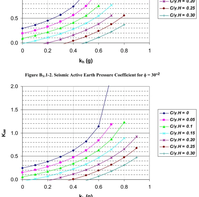
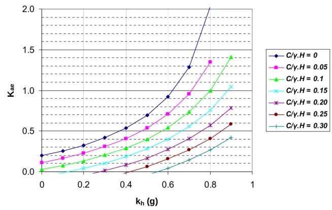
− Appendix BX – This appendix includes a series of charts that can be used to estimate seismic active and passive earth pressures for sites that are characterized by some apparent cohesion in the soil (i.e., not a clean, cohesionless soil). These charts were developed and presented because many natural slopes include some amount of fines, and this fines content has a significant effect on the seismic earth pressure – leading to lower active pressure values and higher passive pressure values than would be estimated if the cohesive content is not included. This effect is particularly important when estimating seismic passive pressures.
• Section Y: Slopes and Embankments – This section provides proposed specifications and commentaries for the seismic design of slopes and embankments. The specifications cover natural slopes and engineered fills. A methodology for addressing sites with liquefaction potential is included in the specifications. AASHTO LRFD Bridge Design Specifications being used at the time of the NCHRP 12-70 Project did not provide specific guidance on methods to use when evaluating the stability of slopes under gravity and live loads. In this case the Specifications and Commentaries use the “standard of geotechnical practice” as the starting point for design. This section includes one appendix.
− Appendix AY – This appendix contains two flowcharts: (1) one showing a strategy for deciding on acceptable displacements (Figure AY-1) and (2) a flowchart showing the overall design process for slopes and embankments (Figure AY -2).
• Section Z: Buried Structures – This section covers the seismic design of drainage structures and small pedestrian tunnels. This discussion focuses on design for transient ground
displacements (TGD) and includes brief mention of the design requirements for permanent ground displacement (PGD). Generally, the ability of the drainage structure or small pedestrian tunnel to withstand permanent ground displacement depends on the amount of permanent ground movement which will occur during the seismic event. Procedures given in Section Y can be used to estimate these displacements. Drainage structures or small pedestrian tunnels will generally move with the ground, and if movements exceed more than few inches, the movements could damage the drainage structure, culvert, or small tunnel. This section includes one appendix.
− Appendix AZ – This appendix summarizes a strategy that the Owner could use for deciding whether seismic design is required. The appendix includes a flowchart showing the overall design process for buried structures (Figure AZ -1).
1.3.2 Part 2 – Example Problems
Part 2 contains the example problems. These are organized as follows: • Retaining Walls
− Gravity and semi-gravity walls − Nongravity cantilever walls − Anchored Walls
− MSE Walls − Soil Nail Walls
• Slopes and Embankments − Natural Slopes
− Fill Slopes • Buried Structures
− Oval Structures − Box Structures
1.4 Use of Recommended Specifications and Commentaries
The specifications, commentaries, and example problems in this volume of the Draft Final Report were prepared based on literature reviews and evaluations that were performed during the NCHRP 12-70 Project. A number of uncertainties regarding the seismic design of retaining walls, slopes and embankments, and buried structures were identified as the reviews and evaluations were performed and as approaches were developed and tested. In some cases these uncertainties simply could not be adequately investigated within the budget and schedule for the Project, and engineering judgment and experience had to be used during the preparation of the specifications and commentaries. The following subsection provides comments on the general use of the specifications and commentaries. This discussion is followed by specific topics that will require further evaluation to address current uncertainties.1.4.1 General Use
The approaches identified in these specifications and commentaries have been tested on a limited number of example problems. Additional trial applications will be required to confirm that the recommended approaches are resulting in reasonable design recommendations. In some cases the recommended approaches can be tested against field observations or controlled laboratory experiments, such as by conducting model tests with the centrifuge. However, in many cases engineering judgment will have to be used to decide whether the design seems to make sense. Individuals experienced in the actual design and construction of retaining walls, slopes and embankments, and buried structures will need to be involved in these evaluations. The reader also should be aware that it is unlikely that these specifications and commentaries will be adopted by AASHTO in their current form. Before implementing all or portions of these recommended specifications and commentaries, AASHTO subcommittee(s) will review and only adopt those sections that are judged by the committee(s) as being suitable for use in the AASHTO LRFD Bridge Design Specifications. For this reason some of the recommended specifications and commentaries may be changed substantially or be replaced entirely by
different specification language and even specification approaches. Those individual attempting to use these specifications and commentaries must realize this limitation. Until some or all of the recommended specifications and commentaries have been officially adopted by AASHTO, the recommendations in this volume of the Draft Final Report must be treated as the approach
recommended by the NCHRP 12-70 Project team. Alternate approaches may be possible and even preferred.
1.4.2
Specific Topics for Further Evaluation
The following specific topics were identified during the preparation of these specifications, commentaries, and example problems as warranting further evaluation and in some cases will require further research. In some cases these topics result in uncertainties in the seismic design; in other cases, the topic represents a departure from the current method being used by
AASHTO. Users should keep these specific topics in mind if they attempt to use all or part of the specifications and commentaries. As AASHTO committee members consider these
specifications and commentaries, they may want to discuss whether further investigation of the topic is needed or whether an alternate approach could be taken that completely avoids the issue.
1.4.2.1 Ground Motions and Soil Properties
The first series of topics applies to ground motions and soil properties used for the seismic design of retaining walls, slopes and embankment, and buried structures.
• Further testing of the screening methods in Articles X.4.1, Y.5.1, and Z.1 is required. Likewise, recommendations for the wave scattering (incoherence) factor given in Article X.4 may require further evaluation.
• Simplified equations for estimating permanent displacement (Article X.4.5) would be desirable. The current equations are not necessarily easy to adapt into a spreadsheet solution that allows the yield acceleration to be identified for a combination of allowable displacement and peak ground acceleration.
• The amount of apparent cohesion that should be used in design is based on estimated fines content (Article X.5). This requires further evaluation, particularly in terms of the effects of cyclic loading on this contribution.
• The potential effects of shear banding in cohesionless soils on the development of seismic active earth pressures needs further review. This mechanism could limit the magnitude of seismic active earth pressures by controlling the failure plane from which seismic pressures develop.
• Liquefied soil properties are currently defined for level-ground conditions, with the assumption that these properties will also apply for sloping ground. This assumption is known to be inaccurate in some situations. Simplified methods that account for sloping ground effects on liquefaction need to be re-evaluated and confirmed.
1.4.2.2 Retaining Walls
The next series of topics deals with retaining walls. In many cases the topic is applicable to several retaining wall types.
• The limit equilibrium method and the simplified Newmark displacement approach are recognized as simple representations of the response of gravity and semi-gravity retaining walls during seismic loading (Article X.7.3). A simplified displacement-based
approach that uses springs to represent the foundation-soil interface for retaining structures is needed, particularly for more accurately evaluating deformations and stresses in the retaining wall. This approach might be analogous to the use of computer programs such as L-Pile or BMCOL for the design of pile foundations subjected to lateral loads.
• For semi-gravity retaining walls the contribution of the soil above the heel of the wall on internal stresses and deformations in the wall needs further evaluation (Article X.7.3.3). The recommended specifications assume that no additional inertial forces from this soil mass occur in the evaluation of wall bending moments and shear forces.
• The influence of the distribution of the seismic coefficient near the top of tall anchored walls needs further evaluation (Article X.9.2.1). For most cases this is not considered a problem, but there could be combinations of soil conditions, slope geometry, and wall stiffness where the distribution of the seismic coefficient could influence bending moments and anchor forces.
• Simplified equations for the determination of seismic passive pressure are needed (Article X.8.2.2). The wedge procedure suggested in Appendix BX offers an excellent approach, but may be difficult to implement for some users. Ideally, the Caltrans’ program CT-FLEX would be made available.
• The distribution of seismic loads to anchors is assumed to be the same as static loading (Article X.9.2.2). This needs further evaluation through numerical modeling, laboratory (centrifuge) experimentation, and field testing.
• The amount of reinforced mass used in the external stability analyses in MSE walls is limited to 0.7 times the wall height (Article X.10.3.2). This length is greater than required by AASHTO, but less than would occur if the entire reinforced zone were included, particularly in the case of tall walls in highly seismic areas where steep backslopes occur above the wall. Numerical or centrifuge studies will be required to evaluate this issue. • The recommended specifications and commentaries remove the (1.45 – A)A factor
currently given in AASHTO (Article X.10.2.2). If this change is adopted as
recommended, computer software such as MSEW and ReSSA will need to be modified. • The distribution of seismic forces within the reinforced zone of MSE walls, as required
for internal stability evaluations (Article X.10.3.3), needs to be re-evaluated. Methods recommended in the specifications and commentaries differ from current AASHTO procedures.
• The soil nail wall specifications need to be made consistent with AASHTO LRFD Bridge Design Specifications for gravity load, once the specifications for static design of soil nail walls are prepared and adopted by AASHTO.
• The effects of seismic loads on the state of stress behind retaining walls following a large seismic event are also largely unknown, and therefore warrants more review. For
example, if relatively large permanent displacements occur for a semi-gravity wall, it is unclear whether the wall will regain its original capacity to resist seismic loads or would
undergo even larger displacements during a similar earthquake in the future. This question could affect the post-earthquake mitigation strategy to adopt.
1.4.2.3 Slopes and Embankments
The next three topics deal with the seismic design of slopes and embankments.
• Methods for evaluating the strength of liquefied soils (Article Y.4) are needed, similar to the comment made for retaining walls. Likewise, the amount of cohesion to allow, particularly if associated with capillarity requires further consideration.
• A recommendation is made to reduce the strength parameters by a factor of 0.9 if the magnitude of the earthquake exceeds 7.5. Common practice in some areas is to apply the 0.9 factor regardless of earthquake magnitude. A consensus approach is required in this areas.
• Further evaluations of the screening levels in Article Y.5.1, including levels for
liquefaction, are needed. It is possible that the screening criteria for central and eastern United States might be different than western United States. In this case a velocity-based criteria might be more suitable, similar to the method used for buried structure design.
1.4.2.4 Buried Structures
The final topics deal with buried structures.
• Further evaluations are need to verify that simplified methods for TGD are appropriate for a range of soil types, buried structure types (rigid and flexible), and buried structure geometries.
• Further guidance on simplified approaches to use for TGD with semi-slip should be considered.
1.5
Limitations
The opinions and conclusions expressed or implied in this Draft Final Report are those of the Project Team. They are not necessarily those of the Transportation Research Board, the National Research Council, the Federal Highway Administration, the American Association of State Highway and Transportation Officials, or the individual states participating in the National Cooperative Highway Research Program.
Inasmuch as these specifications and commentaries are dependent on the level of ground shaking, the soil conditions at the site, and the methods used for gravity loading design, it is the responsibility of the user to decide whether the methods recommended in these specifications are appropriate and meaningful.
Part 1
Specifications and Commentaries
June 2008
SECTION X: RETAINING WALLS
TABLE OF CONTENTS
X.1 SCOPE X-1
X.2 DEFINITIONS X-3
X.3 NOTATION X-5
X.3.1 General X-5
X.4 SEISMIC LOADS AND LOAD FACTORS X-6
X.4.1 General X-6
X.4.2 Design Acceleration Values at Ground Surface X-7
X.4.3 Maximum Seismic Coefficient for Design X-12
X.4.4 Displacement-Related Seismic Coefficient Reduction for Gravity Walls X-16
X.4.5 Newmark Displacement Estimates X-18
X.5 SOIL PROPERTIES X-22
X.6 LIMIT STATES AND RESISTANCE FACTORS X-26
X.6.1 General X-26
X.7 GRAVITY AND SEMI-GRAVITY WALLS X-27
X.7.1 General X-27
X.7.2 Methods of Analysis X-29
X.7.2.1 Seismic Active and Passive Earth Pressure Determination X-31
X.7.2.1.1 M-O Active Earth Pressure Equation X-32
X.7.2.1.2 Seismic Passive Earth Pressure Charts X-38
X.7.2.1.3 Generalized Limit Equilibrium Method X-40
X.7.2.2 Wall Displacement Analysis X-41
X.7.3 Design Requirements X-42
X.7.3.1 Global Stability X-43
X.7.3.2 External Stability X-43
X.7.3.3 Internal Stability X-45
X.8 NONGRAVITY CANTILEVER WALLS X-46
X.8.1 General X-46
X.8.2 Methods of Analysis X-47
X.8.2.1 Seismic Active Earth Pressure X-48
X.8.2.2 Seismic Passive Earth Pressure X-50
X.8.2.3 Wall Displacement Analysis X-52
X.8.3 Design Requirements X-54
X.8.3.1 Global Stability X-54
X.8.3.2 Internal Stability X-55
X.9 ANCHORED WALLS X-56
X.9.1 General X-56
X.9.2 Methods of Analysis X-57
X.9.2.1 Seismic Active Earth Pressure and Anchor Loads X-57
X.9.2.2 Seismic Passive Earth Pressure X-61
X.9.3 Design Requirements X-62
X.9.3.1 Global Stability X-62
X.9.3.2 Internal Stability X-62
X.10 MECHANICALLY STABILIZED EARTH (MSE) WALLS X-63
X.10.1 General X-63
X.10.2 Methods of Analysis X-64
X.10.2.1 Seismic Active Earth Pressure X-65
X.10.2.1.1 M-O Equation for Seismic Earth Pressure X-66
X.10.2.1.2 Wedge Equilibrium and Generalized Limit Equilibrium
Method for Seismic Earth Pressure X-67
X.10.2.2 Wall Displacement Analysis X-68
X.10.3 Design Requirements X-68
X.10.3.1 Global Stability X-69
X.10.3.2 External Stability X-69
X.10.3.3 Internal Stability X-71
X.11 PREFABRICATED MODULAR WALLS X-73
X.11.1 General X-73
X.11.2 Methods of Analysis X-73
X.11.2.1 Seismic Earth Pressure X-74
X.11.2.2 Wall Displacement Analysis X-75
X.11.3 Design Requirements X-76
X.11.3.1 Global Stability X-76
X.11.3.2 External Stability X-76
X.11.3.3 Internal Stability X-77
X.12 SOIL NAIL WALLS X-77
X.12.1 General X-77
X.12.2 Methods of Analysis X-79
X.12.2.1 Seismic Coefficient X-80
X.12.2.2 Displacement Analysis X-81
X.12.3 Design Requirements X-81
X.12.3.1 Global Stability X-81
X.12.3.2 External Stability X-82
X.12.3.3 Internal Stability X-82
REFERENCES X-83
Appendix AX: Strategy for Owner Decision-Making on Acceptable
Displacements for Retaining Walls
Appendix BX: Charts for Determining Seismic Active and Passive
X.1 SCOPE C.X.1
This section provides requirements for the seismic design of retaining walls used in highway construction to stabilize fills or cut slopes but not connected to or forming part of a bridge. These retaining walls, referred to in this section of the Specifications as freestanding retaining walls, shall be designed to withstand seismic loads and displacements associated with the design seismic event in accordance with the requirements of this section of the Specifications.
Before conducting seismic analyses and design evaluations described in this section of the Specifications, freestanding retaining walls shall be designed to satisfy all static service and strength limit requirements specified in Sections 3, 10, and 11 of the
AASHTO LRFD Bridge Design
Specifications.
Freestanding retaining walls stabilize fill soils or cut slopes by providing lateral support or reinforcement. The design process for these retaining walls involves sizing the wall to meet gravity load and live load requirements and then providing a check to confirm that seismic performance is within acceptable limits. The seismic checks include levels of shear and bending stresses in the structural components of the wall, as well as checks on the external and global stability of the wall. If seismic loads result in unacceptable performance in terms of either excessive stresses or displacements, the geometry or detailing of the wall needs to be modified until acceptable performance occurs.
The seismic analysis is conducted by geotechnical and structural engineers. The initial phase of the design is conducted by the geotechnical engineer. This work involves defining
• The soil resistance to loading,
referred to as the capacity (C). The capacity depends on soil factors (e.g., shear strength of the soils) and the geometry of the foundation.
• The seismic earth pressure loading
condition, referred to as the demand (D). In addition to the seismic earth pressure, the seismic demand can also include the seismic inertial forces and seismic hydrodynamic forces for some types of retaining walls.
The capacity (C) and the demand (D) are used by the geotechnical and the structural engineer to confirm that the retaining wall meets (1) global stability, (2) external stability (i.e., sliding, overturning, and bearing), and (3) internal capacity with
respect to shear and moment (also referred to as internal stability in this Section) of structural components. In these analyses
• The global stability involves
traditional slope stability evaluations where soil failure occurs below the retaining structure.
• The external stability considers the
structure as a rigid body and evaluates sliding, overturning, and bearing for the imposed seismic earth pressures; and
• The internal stability deals with the
shear and moment capacity and deformations of the structural system. Normally, the geotechnical engineer will evaluate global stability, the geotechnical or structural engineer will evaluate external stability, and the structural engineer will determine internal stability. For some wall types, such as anchored walls and mechanically stabilize earth (MSE) walls, the geotechnical engineer will also handle all or portions of the internal stability evaluation. Each designer must determine the optimum approach for addressing these wall design needs.
There is a hierarchy to consider when approaching the seismic design of freestanding retaining walls. From reconnaissance surveys following past earthquakes, retaining walls that suffered structural distress were typically classified as having unacceptable damage, even though these structures did not collapse. However, retaining walls that maintained their structural integrity but underwent measurable permanent displacement and rotation were often classified as having acceptable damage. Emergency repairs could usually be made very quickly to any damage resulting from permanent
displacement and rotation, but structural damage usually took much more time and capital investment.
This experience suggests that permanent movement (i.e., sliding and rotation) is acceptable as long as there is no associated structural failure and as long as the displacement does not result in the failure of critical utilities or involve other
secondary considerations. Appendix AX
provides a discussion of factors that the Owner should consider when determining acceptable displacements.
From this point of view, the internal stability issue has a much higher hierarchy in the design process – requiring that the designer assure a higher margin of performance for internal stability than for global and external stability. In establishing the seismic design specifications within the scope of this document, specifications have been written to reflect the above experience and concepts.
X.2 DEFINITIONS
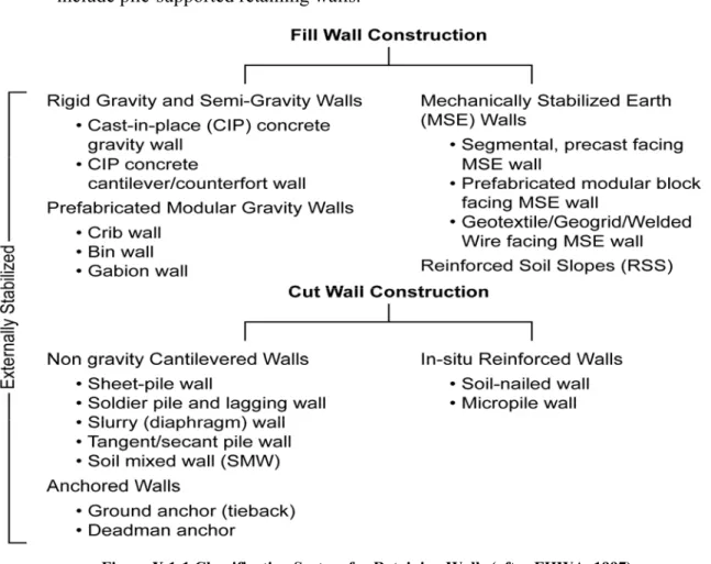
A classification system for retaining walls is shown in Figure X.1-1, (FHWA, 1996). Walls are classified according to construction method (i.e., fill construction or cut construction) and basic mechanisms of lateral load support (i.e., externally stabilized or internally stabilized). Fill wall construction refers to a wall system in which the wall is constructed from the base of the wall to the top (i.e., “bottom-up” construction). Cut wall construction refers to a wall in which the wall is constructed from the top of the wall to the base (i.e., “top-down” construction).
It is important to recognize that the “cut” and “fill” designations refer to how the wall is constructed, not necessarily the nature of the earthwork (i.e., cut or fill) associated with the project. For example, a fill wall, such as a prefabricated modular wall, may be used to retain earth for a major highway cut. Externally stabilized wall systems utilize an external structural wall, against which stabilizing forces are mobilized. Internally stabilized wall systems employ reinforcement which extends within and beyond the potential failure mass.
The following wall types are addressed in these Specifications:
• Rigid Gravity (mass concrete) and Semi-Gravity (standard concrete cantilever) Walls—These walls (often termed conventional retaining walls) derive their capacity
through a combination of the dead weight of the wall and structural resistance.
• Nongravity Cantilevered Wall—These walls derive resistance through shear and
include pile-supported retaining walls.
Figure X.1-1 Classification System for Retaining Walls (after FHWA, 1997)
• Anchored Walls—These walls derive resistance in a manner similar to a nongravity
cantilevered wall, but substantial additional support is obtained through the use of anchors. Anchors may be prestressed tie-backs (ground anchors) which extend from the wall face back to a grouted zone, or they can be deadman anchors which extend from the wall face back to a mechanical anchorage such as a steel sheet pile or concrete block.
• Mechanically Stabilized Earth (MSE) Walls—These walls employ either metallic
(strip, grid, or wire mesh) or polymer (strip, grid, or sheet) reinforcement in the backfill soil. The metallic or polymer reinforcement resists lateral load through interface shear and passive resistance between the soil and the reinforcement. The reinforcement is connected to a vertical or near-vertical facing.
• Reinforced Soil Slopes (RSS)—These systems employ tensile reinforcement in the
backfill soil in a manner similar to MSE walls. The inclination of the slope face is typically less than 70 degrees. The reinforcement extends to the slope face and is connected to a facing, where present.
• Prefabricated Modular Walls—These walls employ interlocking soil-filled or
wall.
• Soil Nail Walls—These walls employ metallic bars that are drilled and grouted, or
driven into the retained soil mass to develop resistance at each level.
X.3 NOTATION
X.3.1 General
A = area (ft.2)
Ae = area in contact during liftoff of footing (ft.2)
As = peak seismic ground acceleration coefficient modified by zero-period site factor
(i.e., As= Fpga PGA) (dim.)
C = capacity (kip or kip/ft.) c = soil cohesion (psf.) D = demand (kip or kip/ft.)
d = displacement (in.)
Fpga = site factor for PGA (dim.)
Fa = site factor for short-period spectral acceleration (dim.)
Fv = site factor for spectral acceleration at 1 second (dim.)
g = gravitational acceleration H = height of retaining wall (ft.)
i = backfill slope angle (degrees)
KAE = seismic active earth pressure coefficient (dim.)
KPE = seismic passive earth pressure coefficient (dim.)
kh = horizontal seismic coefficient (dim.)
kmax = peak seismic coefficient = Fpga PGA = As
kav = average seismic coefficient after adjustments for wave scattering effects = α kmax
(dim.)
ky = yield acceleration coefficient for displacement analysis (dim.)
Lei = effective resistance length for MSE wall reinforcing (ft.)
N = Standard Penetration Test (SPT) blowcount (blows/ft.)
Navgh = average SPT resistance for the top 100 ft of soil profile (blows/ft.)
P = load (kip)
PAE = seismic active earth pressure (kip/ft)
PPE = seismic passive earth pressure (kip/ft.)
PGA = peak ground acceleration coefficient on rock (Site Class B) (dim.) PGV = peak ground velocity at ground surface (in/sec)
Qi = load effect due to load component i (kip)
Rn = nominal resistance (kip)
Rult = sliding resistance (kip)
Sa = spectral acceleration coefficient
Ss = spectral acceleration coefficient at 0.2 seconds
S1 = spectral acceleration coefficient at 1 second
Su = undrained shear strength (psf)
T = period (sec.)
Tp = fundamental period of bridge (sec.)
Vs = shear wave velocity (ft/sec.)
α = fill height reduction factor (dim.)
β = spectrum shape factor = FvS1/kmax (dim.)
δ = interface friction between wall and soil or foundation base and soil
γ = soil unit weight (kip/ft.3)
γp = load factor (dim.)
φr = resistance factor (dim.)
φ = soil friction factor (degrees) θ = arc tan (kh/(1 – kv) (degrees) X.4 SEISMIC LOADS AND LOAD FACTORS
X.4.1 General C.X.4.1
The seismic loads for freestanding retaining wall design shall be computed on the basis of the seismic ground motions and adjustment methods described in this section of the Specifications, unless approved or directed otherwise by the Owner.
For sites that are not susceptible to liquefaction, a seismic analysis of a freestanding retaining wall is not required if the site-adjusted peak ground acceleration coefficient (Fpga PGA) for the site is less than
the values listed in the following table:
The method used to compute seismic loads is based on ground motion maps developed by AASHTO. These maps provide estimates of the PGA for both a reference soft rock condition (Site Class B), as well as other site conditions.
The levels of peak ground acceleration the ground surface in some areas will be low enough that a check on seismic loading is not required. For these locations sufficient margin exists within the design for gravity loads that the seismic loads can be accommodated without special provisions.
The level of peak ground acceleration which seismic analyses are not required
Slope Angle Above
Wall Fpga PGA
Flat 0.3
3H:1V1 0.2
2H:1V 0.1 Sites not requiring a seismic analysis shall
meet seismic detailing requirements consistent with requirements in the AASHTO
LRFD Bridge Design Specifications for the
Seismic Zone.
depends on the soil conditions at the site and the geometry of the slope above the wall. Screening values of site-adjusted peak ground acceleration coefficient given in this article assume that the retaining walls are not supported on soils that are liquefiable. If liquefiable soils occur, special studies are required to evaluate the whether liquefaction will occur and if it does, the most suitable retaining wall.
The slope angle used in screening refers to the average angle of the slope above the retaining wall. If the slope is characterized by a non-uniform slope, the average angle of the slope from the face of the wall to one wall height behind the wall should be used for determining the average slope value. Linear interpolation can be used when determining the need for a seismic analysis for slopes between those given in the table.
For locations where a seismic analysis is not required, structures should still meet minimum structural detailing requirements for the seismic zone to assure acceptable performance if seismic ground shaking occurs.
X.4.2 Design Acceleration Values at Ground Surface
C.X.4.2
The acceleration value used in the design of freestanding retaining walls shall be defined on the basis of the AASHTO ground motion maps and CD adopted by AASHTO in 2007 unless site-specific methods are used to determine the peak acceleration value. The use of site-specific methods for determining ground motions is subject to the approval of the Owner.
The acceleration values determined from the AASHTO maps shall be adjusted for local site effects using the site classes and short period spectral acceleration values given in Table X.4-1. If permissible by the Owner, site-specific dynamic response methods can also be used to estimate the effects of local
The AASHTO ground motion maps and CD were developed by U.S. Geological Survey (USGS) for AASHTO to revise the seismic hazard level used in the design of bridges and related structures, including freestanding retaining walls. The revision changes the design hazard level from 10% in 50 years to a hazard level of 7% in 75 years. This revised hazard level corresponds to an approximate earthquake return period of 975 years.
Hazards maps have been prepared for the revised earthquake return period. The basis for the revised maps is provided in the NCHRP 20-07 Report titled
Recommended LRFD Guidelines for the
site conditions on the acceleration value used for design.
A load factor γp = 1.0 shall be used with
the site-adjusted PGA values to compute seismic loads for the Extreme Event I limit state, except as noted in the following sections in these Specifications.
Seismic Design of Highway Bridges
prepared by TRC/Imbsen and Associates Inc. (NCHRP, 2006a).
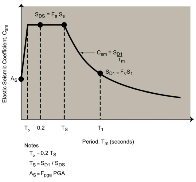
The 2008 AASHTO maps provide PGA and response spectral acceleration coefficients at short and 1 second periods (Ss and S1) for soft rock (Site Class B) site
conditions. The design response spectrum is computed for structural design using a three-point method, as shown in Figure C.X.4-1.
For sites that are not Class B, spectral ordinates are modified by multiplying the reference spectral ordinates for soft rock
(i.e., PGA, Ss, and S1 from the AASHTO
maps) by site factors Fpga, Fa, and Fv. The
site factors are defined in Table X.4-1. The intent of the Fa and Fv factors is to account
for modifications to the seismic ground motions that occur between the rock reference condition (Site Class B) and the average soil conditions at a site. The site class is determined by the average shear wave velocity (Vs) over a depth of 100 feet.
The AASHTO maps are available with a ground motion software tool packaged on a CD-ROM for installation on a PC using a Windows-based operating system. The CD facilitates interpretation of the AASHTO maps by allowing the user to calculate the mapped spectral response accelerations as described below:
• Site Class B (soft rock): PGA, Ss,
and S1 are determined using the
AASHTO CD for the latitude-longitude or zip code of the site. Resulting accelerations are for a reference soft rock (Site Class B) condition.
• Site Classes A, C, D, and E (hard rock or soil): PGA, Ss, and S1 for
Site Class B are modified by multiplying the site factors (Fpga, Fa
and Fv) to define accelerations at sites
Class B).
For some sites or projects the Owner may decide that the AASHTO maps are not appropriate, either because new seismic hazard information is available for a site or a longer return period (i.e., lower frequency of occurrence than 7% in 75 years) is desired for the particular structure. In this case site-specific seismic hazard analyses can be performed to develop site-specific information about the potential for ground shaking at a site.
These site-specific seismic hazard analyses can be based on either deterministic or probabilistic procedures. The decision to use alternate methods of determining the seismic hazard level for a site must be determined in consultation and agreement with the Owner. The proposed AASHTO Guide Specifications for LRFD Seismic Bridge Design (2008) limit the results of site-specific hazard analyses to 2/3rds of the spectrum obtained from the AASHTO maps.
Figure C.X.4-1 Design Response Spectrum Construction Using Three-Point Method
Table X.4-1: Site Classification Categories A-E and Site Coefficients Fpga, Fa, and Fv
a) Site Classification Definitions
Site Class Soil Type and Profile
A Hard rock with measured shear wave velocity, Vs > 5,000 ft/sec.
B Rock with 2,500 ft/sec < Vs≤ 5,000 ft/sec
C Very dense soil and soil rock with 1,200 ft/sec < Vs≤ 2,500 ft/sec,
or with either Navg > 50 blows/ft or Su≥ 2.0 ksf
D Stiff soil with 600 ft/sec ≤ Vs≤ 1,200 ft/sec, or with either 15 ≤ Navg ≤ 50
Site Class Soil Type and Profile
E Soil profile with Vs < 600 ft/sec or with either Navg < 15 blows/ft or Su <
1.0 ksf, or any profile with more than 10 ft of soft clay with PI > 20, m/c > 40% and Su < 0.5 ksf.
F Soils requiring site-specific evaluations, such as
• Peats or highly organic clays (H > 10 ft or peat or highly organic
clays where H = thickness of soil)
• Very high plasticity clays (H > 25 ft with PI > 75)
• Very thick soft/medium stiff clays (H > 120 ft)
Exception: Where the soil properties are not known in sufficient detail to determine the site class, a site investigation shall be undertaken sufficient to determine the site class. Site classes E or F should not be assumed unless the authority having jurisdiction determines that site classes E or F could be present at the site or in the event that site classes E or F are established by geotechnical data.
where
Vs = Average shear wave velocity for the upper 100 ft of the soil profile
Navg = Average Standard Penetration Test (SPT) blowcount in blow/ft (ASTM D
1586) for the upper 100 ft of the soil profile
Su = Average undrained shear strength in ksf (ASTM D 2166 or ASTM D 2850)
for the upper 100 ft of the soil profile PI = Plasticity index (ASTM D 4318) m/c = Moisture content (ASTM D 2216)
b) Values of Site Factor (Fpga) at Zero Period on Acceleration Spectrum Peak Ground Acceleration Coefficient (PGA)a
Site Class PGA ≤ 0.10 PGA = 0.20 PGA = 0.30 PGA = 0.40 PGA ≥ 0.50
A 0.8 0.8 0.8 0.8 0.8 B 1.0 1.0 1.0 1.0 1.0 C 1.2 1.2 1.1 1.0 1.0 D 1.6 1.4 1.2 1.1 1.0 E 2.5 1.7 1.2 0.9 0.9
Fb * * * * *
Notes:
a) Use straight line interpolation for intermediate values of PGA.
b) Site-specific geotechnical investigation and dynamic site response analyses should be performed for all sites in Site Class F following the current AASHTO LRFD Bridge Design Specifications.
c) Values of Site Factor (Fa) for Short-Period Range of Acceleration Spectrum Spectral Acceleration Coefficient at Period 0.2 sec (Ss)a Site Class S
s≤ 0.25 Ss = 0.50 Ss = 0.75 Ss = 1.00 Ss ≥ 1.25
A 0.8 0.8 0.8 0.8 0.8 B 1.0 1.0 1.0 1.0 1.0 C 1.2 1.2 1.1 1.0 1.0 D 1.6 1.4 1.2 1.1 1.0 E 2.5 1.7 1.2 0.9 0.9
Fb * * * * *
Notes:
a) Use straight line interpolation for intermediate values of Ss.
b) Site-specific geotechnical investigation and dynamic site response analyses should be performed for all sites in Site Class F..
d) Values of Site Factor (Fv) for Long-Period Range of Acceleration Spectrum
Spectral Acceleration Coefficient at Period 1.0 sec (S1)a Site Class S
1≤ 0.25 S1 = 0.50 S1 = 0.75 S1 = 1.00 S1 ≥ 1.25
A 0.8 0.8 0.8 0.8 0.8 B 1.0 1.0 1.0 1.0 1.0 C 1.7 1.6 1.5 1.4 1.3 D 2.4 2.0 1.8 1.6 1.5 E 3.5 3.2 2.8 2.4 2.4
Fb * * * * *
Notes:
a) Use straight line interpolation for intermediate values of S1.
b) Site-specific geotechnical investigation and dynamic site response analyses should be performed for all sites in Site Class F.
X.4.3 Maximum Seismic Coefficients for Design
C.X.4.3
The maximum seismic coefficient (kmax)
for computation of seismic lateral wall loads shall be determined on the basis of the PGA at
the ground surface (i.e., kmax = Fpga PGA),
The definition of kmax is identical to As
used in the current AASHTO LRFD
Bridge Design Specifications. Different
except for walls founded on Category A soil
(hard rock) where kmax shall be based on 1.2
times the site-adjusted peak ground acceleration coefficient (i.e., kmax = 1.2 Fpga
PGA). If permitted by the Owner, wall-height adjustment factors are allowed for walls greater than 20 feet in height. For wall heights greater than 70 feet, special seismic design studies shall be performed.
proposed Specifications to be consistent with historic use of “k” in the evaluation of seismic earth pressures.
The designer can conservatively kmax
for design; however, various studies have shown that the ground motions in the mass of soil behind the wall will often be lower than the kmax at the ground surface,
particularly for taller walls. The following discussions outline the adjustment that can be used by the designer to account for this effect and the rationale for the adjustment.
Height-Dependent Adjustments for Wall Heights from 20 to 70 feet
For values of H greater than 20 feet but less than 70 feet, the seismic coefficient used to compute lateral loads acting on a freestanding retaining wall may be modified to account for the effects of spatially varying ground motions behind the wall, using the following equation:
kav = α kmax (C.X.4.3-1)
where
kmax = Fpga PGA
α = fill height reduction factor For Site Category C, D, and E
α = 1 + 0.01H [(0.5β) - 1] C.X.4.3-2) where
H = fill height (feet)
β= FvS1/ kmax
For Site Category A and B (hard and soft
rock foundation soils), the values of α
given by Equation C.X.4.3-1 is increased by a factor of 1.2.
Height-Dependent Adjustments for Wall Heights > 70 feet
For wall heights greater than 70 feet, special seismic design studies involving the use of numerical models should be conducted. These special studies are required in view of the potential consequences of failure of these very tall walls, as well as limitations in the simplified wave scattering methodology.
Basis for Height Adjustment Factor
The basis for the height-dependent reduction factor described above is related to the response of the soil mass behind the retaining wall. Common practice in selecting the seismic coefficient for retaining wall design has been to assume rigid body soil response in the backfill behind a retaining wall. In this approach the maximum seismic coefficient (kmax) is assumed equal to the
Fpga PGA when evaluating lateral forces
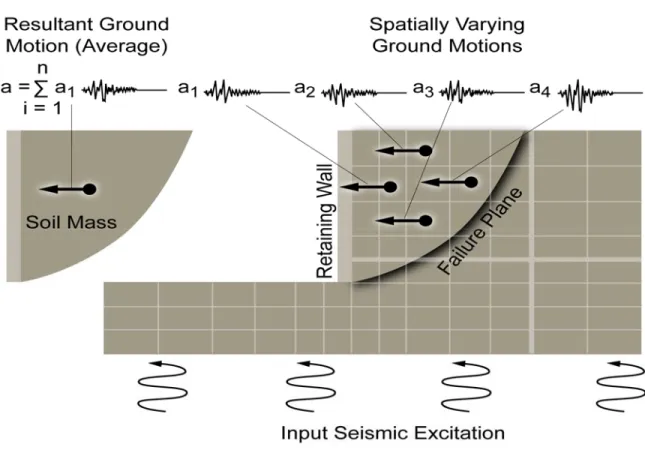
acting on an active pressure failure zone. Whereas this assumption may be reasonable for wall heights less than about 20 feet, for higher walls, the magnitude of accelerations in soils behind the wall will vary spatially as shown schematically in Figure C.X.4-2.
The nature and variation of the incoherent ground motions is complex and will be influenced by the dynamic response of the wall-soil system to the input earthquake ground motions. In addition to wall height the acceleration distribution will depend on factors such as the frequency characteristics of the input ground motions, the stiffness contrast between backfill and foundation soils, and wall slope. From a design standpoint, the net effect of the spatially varying ground motions can be represented by an averaging process over a potential active pressure zone, leading to a time history of average acceleration
and hence a maximum average acceleration or seismic coefficient as shown in Figure C.X.4-2.
To evaluate this averaging process, the results of a series of analytical studies are documented in the NCHRP 12-70 Report (NCHRP, 2008). An evaluation of these results forms the basis for the simplified equations C.X.4.3-1 and C.X.4.3-2. The analytical studies included wave scattering analyses assuming elastic soil media using different wall heights and slopes and a range of earthquake time histories. The acceleration time histories simulated spectral shapes representative of Western United States (WUS) and Central and Eastern United States (CEUS) sites and reflected different earthquake magnitudes and site conditions.
Additional height-dependent, one-dimensional SHAKE (Schnaebel et al., 1972) analyses were also conducted to evaluate the influence of nonlinear soil behavior and stiffness contrasts between backfill and foundation soils. These studies were also calibrated against finite element studies for MSE walls documented by Segrestin and Bastick (1988), which form the basis for the average maximum acceleration equation
(a function of As) given in the current
AASHTO LRFD Bridge Design
Specifications for MSE walls.
The results of these studies demonstrate that the ratio of the maximum average seismic coefficient (kav) to kmax (the α factor) is primarily
dependent on the wall height and the
shape of the acceleration spectra (the β
factor). The acceleration level has a lesser effect. It was also found that equations C.X.4.3-1 and C.X.4.3-2 could be applied to slopes.
Figure C.X.4-2 Average Seismic Coefficient Concept
X.4.4 Displacement-Related Seismic Coefficient Reduction for Gravity Walls
C.X.4.4
Where limited permanent displacement of a freestanding retaining wall is allowed by the Owner, a 50% reduction in the maximum
seismic coefficient (kmax) shall be permitted
when determining the seismic coefficient used to compute seismic lateral earth pressure wall loads for gravity walls (i.e., rigid and semi-rigid gravity walls, MSE walls, modular block walls, and soil nail walls).
Use of the 50% reduction for other retaining walls (e.g., nongravity cantilever and anchored) shall be permitted if analyses demonstrate that the displacements associated with a 50% reduction do not result in (1) yield of structural members making up the wall, such with a pile-supported wall, or (2) overloading of lateral support systems, such as the ground anchors.
Where reductions for wave scattering
If the maximum average seismic coefficient kmax is used for gravity wall
design, the size of wall structures may be excessive if design is based on limit equilibrium principles with zero wall displacement. The concept of designing for a small tolerable horizontal displacement is described in Appendix Section 11.1.1.2 of the current AASHTO
LRFD Bridge Design Specifications. The
concept is based on the Newmark sliding block analogy (Newmark, 1965), where incremental wall sliding displacements occur when horizontal accelerations
exceed a yield acceleration ky
corresponding to an acceleration level for a sliding factor of safety of 1.0.
The Newmark sliding block concept (Newmark, 1965) was originally developed to evaluate seismic slope
effects are permitted by the Owner, the 50% reduction in the maximum seismic coefficient shall be allowed after adjustments for wave scattering.
stability in terms of earthquake-induced slope displacement as opposed to a factor of safety against yield under peak slope accelerations. The concept is illustrated in Figure C.X.4-3, where a double integration procedure on accelerations exceeding the yield acceleration of the slope leads to an accumulated downslope displacement.
The concept of allowing gravity walls to slide during earthquake loading and displacement-based design (i.e., assuming a Newmark sliding block analysis to compute displacements when accelerations exceed the horizontal limiting equilibrium, yield acceleration for the wall-backfill system) was introduced by Richards and Elms (1979). Based on this concept, Elms and Martin (1979) suggested that a design acceleration coefficient of 0.5 PGA would be adequate for limit equilibrium pseudo-static design, provided allowance be made for a horizontal wall displacement in inches of 10 times the PGA. This concept was adopted by AASHTO in 1992, and is reflected in the
current AASHTO LRFD Bridge Design
Specifications. [The PGA term in Elms
and Martin is equivalent to the Fpga PGA
or kmax in these proposed Specifications.]
Use of a seismic coefficient of 0.5
times the kmax for computation of earth
pressure loads is also adopted in these Specifications as further discussed in Article X.7. Recent work completed as part of the NCHRP 12-70 Project (as discussed in Article X.4.5) concluded that the amount of permanent ground displacement associated with the Newmark method is, however, less than previously used. In most cases the amount of movement associated with 0.5 kmax will be less than 1 to 2 inches.
Figure C.X.4-3 Newmark Sliding Block Concept
X.4.5 Newmark Displacement Estimates C.X.4.5
When computing permanent displacement of the freestanding retaining walls, the proposed method of computing seismic deformations shall be reviewed with the Owner to confirm that the proposed method is acceptable to the Owner. A maximum acceptable level of permanent ground displacement shall be established based on the Owner’s minimum performance expectation
for the retaining wall. Appendix Ax to this
section provides a strategy for Owner decision-making on the amount of acceptable displacements.
Various methods can be used to estimate permanent displacements of gravity retaining structures for walls that can move without damaging either adjacent facilities or components of the wall. These methods range from simple equations or charts based on the Newmark method to using numerical modeling. For many situations simple equations or charts will be sufficient; however, as the complexity of the site or the wall-soil system increases, more rigorous numerical modeling methods become advantageous.
Current AASHTO Equation for Displacement Estimates
The current AASHTO approach is further discussed in the NCHRP 12-70 Report (NCHRP, 2008) where it is noted that the current AASHTO displacement
equation (in inches) is given as: d = 0.087(PGV)2/kmaxg (ky/kmax)-4
(C.X.4.5-1)
Revised AASHTO Equation for Displacement Estimates
Additional sliding block displacement analyses were conducted as part of the NCHRP 12-70 Project using an extensive database of earthquake records. The objective of these analyses was to establish updated relationships between wall displacement (d) and the following three terms: the ratio ky/kmax, kmax , and
PGV. Based on regression analyses, the following simplified relationships were established and are recommended for design purposes:
For all sites except CEUS rock sites (Categories A and B), the displacement (in inches) can be estimated by the following equation:
log(d) = -1.51 - 0.74 log(ky/kmax) +
3.27 log(1-ky/kmax) - 0.80
log(kmax) + 1.59 log(PGV)
(C.X.4.5-2) For CEUS rock sites (Categories A and B), displacement (in inches) can be estimated by:
log(d) = -1.31- 0.93 log(ky/kmax) +
4.52 log(1-ky/kmax) - 0.46
log(kmax) + 1.12 log(PGV)
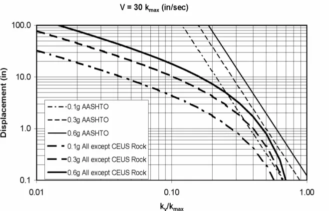
(C.X.4.5-3) Figures C.X.4-4 shows a comparison between the displacements estimated using the old and new equations. Note that the above displacement equations represent mean values, and can be
multiplied by 2 to obtain an 84 percent confidence level.
Similar displacement equations to those recommended in Equations C.X.4.5-2 and C.X.4.5-3 were developed by Martin and Qiu (1994) from a more limited database of earthquake records, and were described in the NCHRP 12-49 Project (NCHRP, 2003). The recommended equations give displacements slightly greater than the Martin and Qiu (1994) correlations.
PGV Equation
In Equations C.X.4.5-2 and C.X.4.5-3 it is necessary to estimate the peak ground velocity (PGV) and the yield
acceleration (ky). Values of PGV can be
determined using the following correlation between PGV and spectral
ordinates at one second (S1) for Site
Class B. PGV (in/sec) =
55 Fv S1 (C.X.4.5-4
where S1 is the spectral acceleration at 1
second and Fv is the Site Class
adjustment for Site Class B.
The development of the PGV-S1
correlation is based on a simplification after regression analyses conducted on an extensive earthquake database established from recorded and synthetic accelerograms representative of both rock and soil conditions for the WUS and CEUS. The study is described in the NCHRP 12-70 Report (NCHRP, 2008). It was found that earthquake magnitude need not be explicitly included in the correlation, as its influence on PGV is captured by its influence on the value of
S1. The equation is based on the mean
plus one standard deviation from the simplification of the regression analysis. (1.46 x the median) for conservatism. Based on Equation C.X.4.5-4, illustrative
values of PGV for Site Class B (i.e., Fv =
1.0) are as follows:
S1 = 0.1 : PGV = 5.5 in/sec
S1 = 0.5 : PGV = 27.5 in/sec
Yield Acceleration (ky)
Values of the yield acceleration (ky)
can be established by computing the seismic coefficient for global stability that results in a C/D ratio of 1.0 (i.e., FS = 1.0). A conventional slope stability program is normally used to determine the yield acceleration. For these analyses the total stress (undrained) strength parameters of the soil should usually be used in the stability analysis, as discussed in the next section.
Alternate Methods of Estimating Permanent Displacement
The revised Newmark equations given above present a simplified method of estimating the displacements that will occur if the C/D ratio for a limiting equilibrium stability analysis is less than 1.0. Alternate methods of estimating permanent displacements can also be used. The most common of the alternatives involves using the computer programs FLAC (Itasca, 2007) or PLAXIS (PLAXIS BV, 2007). Both software packages allow seismic time history analysis of a 2-dimensional model of the soil cross-section. Such models require considerable expertise in the set-up and interpretation of model results, particularly relative to the selection of strength parameters consistent with seismic loading. For this reason use of this alternate approach should be adopted only with the Owner’s concurrence.
Figure CX.4-4 Comparison between AASHTO (2004) and Recommended Displacement Equation C.X.4.5-2 for PGV = 30 kmax (in/sec)
X.5 SOIL PROPERTIES
For competent soils that do not undergo strength degradation under seismic loading, static strength parameters shall be used for seismic design.
• For cohesive soils total stress strength
parameters based on undrained tests shall be used during the seismic analysis.
• For clean cohesionless soils, the
effective stress friction angle of the soil shall be used.
For saturated, sensitive cohesive soils or saturated cohesionless soils, the potential for earthquake-induced strength degradation shall be considered.
The static design of retaining walls in
Section 11 of the AASHTO LRFD
Bridge Design Specifications is based on
the use of effective stress strength parameters. For conservatism the effective cohesion intercept is normally neglected and only the effective friction angle is used. The use of effective stress strength parameters is appropriate for design of retaining walls for long-term, gravity loads. However, for transient seismic loading, total stress parameters are more appropriate for cohesive soils.
Selection of Strength Parameters
Seismic stability analyses for retaining walls require the determination of strength parameters (c and φ) for either or both compacted fill and natural soils. In the case of fill wall construction,
specifications for wall construction usually require backfill materials to be cohesionless and free draining materials (i.e., amount of soil passing the No. 200 sieve less than 5 to 10%). For these soils cohesion (c) is assumed to be zero, and the effective (drained) friction angle (φ’) should be used to characterize the soil strength parameters. This strength can be obtained by conducting effective stress, or drained, laboratory strength tests or through the use of empirical correlations to field measurements, such as the Standard Penetration Test (SPT) blowcount or the cone penetration test (CPT) end resistance.
For wall construction involving cuts in natural ground, a high likelihood of encountering soils with cohesive content exists. The undrained (total stress) strength parameters should be used to characterize these soils for seismic loading analyses. The undrained strength can be determined on the basis of total stress strength parameters by in situ testing (e.g., vane shear tests), or through empirical correlations to results of CPT soundings.
In some geographic areas the availability and cost of clean granular backfill soil is becoming a significant construction issue, and backfill soils with a cohesion component due to fines content are increasingly being used. Gravity walls which involve the use of these “dirty” granular backfill soils may also require determination of total stress strength parameters for evaluation of wall design requirements.
Additional information regarding the characterization of soil strength by field and laboratory testing methods is provided in Section 10 of the current
AASHTO LRFD Bridge Design