Object Detection and Localization
Using Omnidirectional Vision
in the RoboCup Environment
M. Jamzad
, A.R. Hadjkhodabakhshi
1and V.S. Mirrokni
2In this paper, a design and construction method for an omnidirectional vision system is described, including how to use it on autonomous soccer robots for object detection, localization and, also, collision avoidance in the middle size league of RoboCup. This vision system uses two mirrors, at and hyperbolic. The at mirror is used for detecting very close objects around the robot body and the hyperbolic one is used as a global viewing device to construct a world model for the soccer eld. This world model contains information about the position and orientation of the robot itself and the position of other objects in a xed coordinate system. In addition, a fast object detection method is introduced. It reduces the entire search space of an image into a small number of pixels, using a new idea that is called jump points. The objects are detected by examining the color of pixels overlapping these jump points and a few pixels in their neighborhood. Two fast and robust localization methods are introduced, using the angle of several xed landmarks on the eld and the perpendicular borderlines of the eld. Borderline detection uses the clustering of candidate points and the Hough transform. In addition, the omnidirectional viewing system is combined with a front view that uses a plain CCD camera. This combination provided a total vision system solution that was tested in the RoboCup 2001 competitions in Seattle USA. Highly satisfactory results were obtained, both in object detection and localization in desired real-time speed.
INTRODUCTION
In RoboCup, a team of mobile agents plays soccer against another such team in a predened environment. In the middle size league, each team has three players and one goalkeeper. A game is played in two, ten-minute half times. The dimensions of the robots are about 505060 cm and they are fully autonomous
agents. Their movements are not manually controlled but are carried out by their own actuators, sensors and decision-making devices.
The eld dimensions of the middle size league are 510 meters. There is a white color wall of
height 50 cm all around the eld (i.e., the rule until 2001). The eld is covered with green carpet. Robots
*. Corresponding Author, Department of Computer Engi-neering, Sharif University of Technology, Tehran, I.R. Iran.
1. School of Computer Science, Simon Fraser University in Vancouver, BC, Canada.
2. Laboratory of Computer Science, MIT, Cambridge, MA, USA.
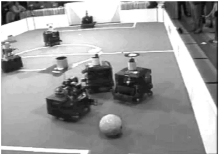
play soccer with a size 4 FIFA red ball. Robots are mostly black, except for an identifying color marker of light blue or purple, on top of them. The goals are 2 meters wide and 90 cm high. One goal is yellow and the other one is blue. Figure 1 shows the picture of a middle size league eld taken in Seattle during RoboCup 2001. A general report, which introduces the dierent teams that participated in RoboCup 2001, is given in [1].
The vision system of a robot detects objects according to their colors. These robots are usually equipped with one or more CCD cameras for their vision system and may also have other sensing devices, such as laser range nders and infrared. In addition, they are equipped with a computer system, hardware control boards and wireless communication devices that allow them to communicate with each other and with a server outside the eld for coordination of the robots behavior. For details, information about RoboCup is available in [2].
Omnidirectional mirrors have been used in uni-versity labs and industry in recent decades. A general description of panoramic camera design and geometry
Figure1. A picture of the middle size RoboCup eld in
2001.
is given in [3]. Detailed theories on catadioptric image formation are given in [4,5]. The ability to view over 360 degrees has many useful applications in machine vision and robotics, for example, surveillance [6], colli-sion avoidance [7], immediate detection of objects [8], robot localization [9], navigation and obstacle detec-tion [10,11], outdoor navigadetec-tion that uses dimension reduction with PCA and histogram matching [12], use of optical ow for motion detection by robots [13], localization and object detection using omnidirectional stereo vision [14], etc.
In RoboCup 1998, the rst application of an omni-directional vision system was introduced by Asada [15] who constructed a goal-keeper tted with an omni-directional vision with a learning capacity. In 2000, Lima [16] used an omnidirectional sensor for the self-localization of a robot in the eld. In 2001, a goal keeper robot that used an omnivision system was introduced by the university of Padua team [17]. In this work, the authors provide a guideline for the design of an omnidirectional vision system for the Robocup domain and its software for object detection.
In the RoboCup 2001 competition, several teams, such as Artisti Veneti (University of Padua, Italy), Sharif CE (Sharif University of Technology, Iran), Fun2Mas (University of Milan, Italy), Fusion (Fukuoka University, Japan), IsocRob 2001 (Institute of Robotic systems, Lisbon), Minho (University of Minho, Portu-gal), Trackies (University of Osaka, Japan) and Eigen (Keio University, Japan), etc. used omnidirectional vision systems on their soccer robots. Descriptions of these teams are available in [18].
In the 2002 RoboCup competition, Isfahan Uni-versity of Technology, Iran, presented omnidirectional mobile robots [19]. The main focus of this paper is on the mechanical design aspects of robots. The authors also provide a short description on omni-mirror and localization.
In 2003, the GMD team from Germany,
in-troduced a localization method, based on landmark detection and the triangulation method [20].
In recent years, almost all teams used an om-nidirectional vision system because of its ability to provide the images usable for high speed object de-tection and, also, reliable robot localization. This high speed is obtained, due to the fact that only one single image, representing a 360 degree view around the robot, is needed to be processed and, also, the fact that the duration of the object appearance in the omnidirectional view eld is longer. Several teams (e.g., such as Sharif CE and Artisti Veneti) designed and manufactured their own customized mirror, but many other teams purchased a pre-fabricated omni-vision set that included the mirror and camera.
The vision system described in this paper has been installed on the robots of Sharif CE middle size robotic team since 2001. Sharif CE has participated in all RoboCup competitions from 1999 to 2002 and has achieved remarkable results (1st place in RoboCup 1999 in Stockholm, 1st place in European RoboCup 2000 in Amsterdam, 3rd place in RoboCup 2000 in Melborne, best engineering challenging award for its paper on robot vision in RoboCup symposium 2001 in Seattle) [21,22].
Although one can take advantage of having dif-ferent sensory devices on a robot, in order to design simple and ecient mobile robots with easier hardware handling, it is worth concentrating only on vision sensors.
To solve the problem of localization, collision avoidance and object detection in the RoboCup eld, the authors have designed and constructed a cus-tomized omnidirectional viewing system that is com-bined with a front view vision system.
The vision system uses two re-wire (IEEE 1394) digital CCD cameras. They are connected via a switching hub to a laptop computer on the robot body, that is, the main processor of the robot. In order for a mobile robot to react quickly and accurately to all changes in its environment, it should be able to detect objects (obstacles) very rapidly and with acceptable accuracy.
The rest of the paper is organized as follows. First, an omnidirectional mirror design for mobile robots is described. Then, the object detection al-gorithms are presented. After that, the localization problem in general, and methods for localization are presented. Finally, experimental results are given and this paper is concluded.
OMNIDIRECTIONAL MIRROR DESIGN
The most common omnidirectional mirrors have a spherical, parabolic, conical or hyperbolic shape. An extensive survey on these mirrors is given in [3,5].
In [17], the authors describe the steps of designing their own customized omnidirectional mirror for a goalkeeper robot. The proposed multi-part mirror is composed of an inner and two outer parts. The inner part is used to see a wide area of the eld of play, while the outer part (i.e., marker mirror and proximity mirror) is used for observation of the other robot markers and the area surrounding the robot. In this work, the inner mirror has a conical shape and the proximity mirror has a concave shape. The authors claim that the disadvantages of a conical mirror (i.e., bad resolution for areas close to sensor, limitations in maximum measurable distance and constant absolute error) were overcomed by taking advantage of the outer proximity mirror, due to its overlap in covering areas that the inner mirror is also covering.
Although it is possible to overcome some disad-vantages of conical mirrors by using the concave shape of a proximity mirror, there are two main diculties with this mirror design. First, some areas around the robot are projected both onto inner and proximity mirrors, therefore, one has to go through additional image processing routines to test images on both mirrors to overcome the disadvantages of the conical mirror. This is a time consuming procedure. Second, in the RoboCup environment, one needs to have good measurement precision for objects closer to the robot, while a certain amount of measurement error is allowed for objects located at a distance. Using a conical shape inner mirror produces a constant measurement error, regardless of object distance. Therefore, the problem in using a conical shape mirror also remains unsolved. In [19] the authors constructed a hyperbolic mirror based on the design given by [23], but did not describe the advantages of this design. This mirror was part of the vision system installed on their omnidirectional robots.
The shape of an omnidirectional mirror is one of the most important factors in determining overall viewing performance [24]. There are two main factors in this regard. First, to cover a wide area around the robot (if possible, all of the soccer eld). Second, to provide an adequate resolution for objects at a relatively far distance.
A good performance, in this regard, guarantees detection of the ball (that is the smallest object on the soccer eld), in most cases, even if it is too far away from the robot. Therefore, considering the advantages and disadvantages of both spherical and conical mirrors for the proposed application, a hyperbolic mirror is choosen, because of the following two main reasons: 1. The projection of far objects on the mirror border
are large enough, such that even a ball located at a relatively far distance can be easily detected; 2. There is much less distortion in the projection
of object shapes on the hyperbolic mirror surface compared to the conical mirror. In addition, by selecting the proper parameters for the hyperbola, all areas of the soccer eld can be visualized on this mirror.
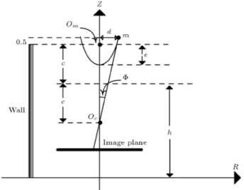
A Model for a Hyperbolic Mirror
Figure 2 shows a geometrical model for this mir-ror. The purpose is to obtain a map between the coordinates of pixels on the image plane and their corresponding points on the soccer eld. This map is calculated, with respect to a coordinate system xed on the robot body.
To nd the map of a point, p, with polar coordi-nate p(r;), on the image plane and its corresponding point P(R;Z;) on the eld, an important property in hyperbolic mirrors [25] is used. That is, as shown in Figure 2, if a light beam initiated from point P on the eld, hits the mirror surface in such a way that its extension passes throughOm(e.g., the rst focus of
the hyperbola, which is located inside the mirror body), then, this light beam will reect in a direction passing through the second focus of the hyperbola (point Oc).
Therefore, one has to install a CCD camera in the second focus of the hyperbola to capture the image reected on the hyperbolic mirror.
According to the illustrations of Figures 2 and 3, the equations of a hyperbolic mirror are given, as follows:
R2
a2
(Z h)2
b2 = 1; (1)
where:
a=p
c2 b2:
Figure 2. Geometrical model for hyperbolic mirror, a
pointP from the world coordinate is projected on pointp
Figure3. Hyperbolic mirror installation specication. R
axis is laid on the eld.
One can calculate the map using the above properties, as follows:
Z=Rtan+c+h: (2)
Since it is known that all objects touch the eld and their bottom hasZ= 0, thus:
tan= c+R :h (3)
According to Figure 2, one can write: tan= b2+c2
(b2 c2) tan+ 2
bc c2 b2
1
cos; (4)
tan=fr : (5)
To simplify the equations, let:
a1=
b2+c2
b2 c2; a 2= 2
bc
c2 b2; a
3= (c+h):
(6) It is assumed that the focal point of the hyperbolic mirror is correctly set on a principal point of the camera lens. Therefore, by Equations 4 to 6, one has:
f
r =a1tan+
a2
cos; (7)
f2
r2
2a1ftan
r +a1tan
2=a2
2(1 + tan
2): (8)
By Equations 3 and 8, one has:
f2
r2
2a1f
a3
R
r +a
2 1a
2 3
R2 =a 2 2(1 +
a2 3
R2); (9)
(f2 r2a2 2)R
2 (2a
1a3fr)R+r 2a2
3(a 2 1 a
2
2)=0: (10)
According to the above equations and considering
Z = 0, if one has the coordinate of a point, p(r;), in the image plane, by solving Equation 10, one can nd the coordinate of its corresponding point,P(R;), on the eld in the robot's coordinate system.
It is important to notice that the angle of point,
P, with respect to the robot's coordinate system origin, is the same as the angle of point p on the image plane, with respect to the image plane center. This condition is satised if the hyperbolic mirror plane is set parallel to the eld, the CCD camera axis is installed perpendicular to the robot chassis (the eld) and the center of the hyperbolic mirror is set along the camera axis, as shown in Figure 4.
One hyperbolic mirror has been fabricated for each of the 4 robots of the soccer robot team using plexiglas material coated with aluminum. The fab-rication was done by a CNC (Computer Numerical Control) machine. The G-code for CNC was obtained using the equations of the hyperbola explained above. The mirror parameters were determined asa= 5:564,
b = 6:658 and c = 8:677. Figure 5 shows one of the hyperbolic mirrors that were constructed. One such mirror is installed inside a plexiglas supporting tube of 15 cm diameter and installed on the chassis of a robot. Figure 6 shows a picture of two robots designed and constructed by the Sharif CE RoboCup team, using the omni-vision system described in this paper. As can be seen in Figure 6, the omni-vision system is installed inside a transparent tube that has a diameter of 15 cm. The robot seen on the right is a player and the one on the left is a goalkeeper.
Figure4. The camera axis is set along the center of
hyperbolic mirror. The at mirror installed on top of hyperbolic mirror is used as a collision detection sensor.
Figure5. A picture of a hyperbolic mirror fabricated by
CNC machine.
Figure6. Two robots with their omni-vision systems
installed inside transparent vertical tubes. The front robot is a player and the one at the back is a goal keeper.
Camera Calibration
As described above, the map between the points on the image plane and their corresponding points on the eld, with respect to the coordinate system on the robot, is a function of the camera and mirror parameters. These parameters aref, as the camera focal distance, anda1,
a2anda3, as given in Equation 6 for mirror parameters.
These parameters cannot be accurately obtained from the camera and mirror specications, therefore, in practical experiments these parameters are determined by using a few sample points from the map function (Equation 10). This process is called: Vision system calibration. The method for such calibration is as follows.
Four points P1(R1;1), P2(R2;2), P3(R3;3)
and P4(R4;4) are set on the eld and, then, their
corresponding reected points; p1(r1;1), p2(r2;2),
p3(r3;3) and p4(r4;4) are measured in the image
plane. By putting these values in Equation 10, one will have four unknowns and four equations, by the solution of which will obtain the parameters,f,a1, a2
anda3.
To improve the accuracy of this map, the actual values obtained for the above four parameters are used as an initial kernel in a local search to nd a set of optimum values for them.
To perform this correction, a set of points,Pi, on
the eld are dened, such that these points are located on the circumference of a few concentric circles centered at the origin of the robot's coordinate system. For each point,Pi, its corresponding pixel,pi, is located on the
image plane and the coordinate of pi is passed to the
mapping function. The dierence between the output of the mapping function and that of its real value is the error of the mapping function for sample point pair (Pi;pi). Then, in the neighborhood of the kernel,
one tries to nd new values for the mapping function parameters, such that these parameters minimize the sum of the squared errors for all sample points.
Calculating the Parameters of a Hyperbolic
Mirror
If one installs the hyperbolic mirror at such a height on the robot that the distance from the eld to the focus of the mirror is the same as the height of the wall (50 cm), and one cuts the mirror hyperbola with a plane parallel to the eld and at a height equal to 50.50 cm (Figure 3 shows this conguration), then, the picture projected on the resulting mirror will have the following properties:
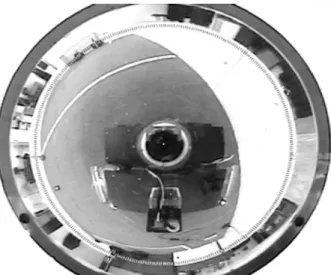
1. No matter where the robot is located on the eld, the upper edges of the walls are always projected on a circle with constant center and radius. The reason for this method of projection is explained in the following sections. Obviously, this circle always passes through both goals. Thus, to nd the goals one can search only on the circumference of this circle. Figure 7 illustrates this property, where one can see the upper edges of the walls are projected on the circumference of a large circle;
2. The upper part of the two goals will always be
Figure 7. The edge of walls and goals are always
projected on the image plane. This is because of the 0.5 cm oset, as shown in Figure 3. This is very helpful for detecting the goals, especially in situations when a few robots and a goalkeeper are inside the goal area.
In these situations, the position of the goals, that is used as landmarks for localization, are detected by processing only the upper part of the goals. This part will never be blocked by any robot, because the maximum allowed height for the robots is smaller than the height of the goals (e.g., 90 cm). Using this setting, according to Figure 3, one can now compute the parameters of the mirror, as follows.
First, one needs to x the radius of the mirror (i.e., d in the equations), such that there is a good quality image for processing. This parameter depends on the quality of the mirror itself. One can use a very small mirror, if it is accurate enough, with very low image distortion, otherwise, one needs to use a bigger one. The mirror that is used in this system has the radius of about 5 cm.
Now, one can compute the value of the parameter,
c, of the mirror from the following equation:
tan =2c+ 0d :5; (11)
where is half of the viewing angle of the camera. On the other hand, since pointmis on the mirror surface, it satises the mirror Equation 1, therefore:
d2
a2
(c+ 0:5)2
b2 = 1: (12)
Thus, by solving the system of equations, including Equations 12 and 1, one can easily compute the values ofaandb.
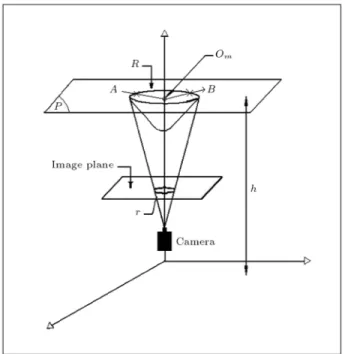
Projection of Wall Edges on Image Plane
There were white walls of height 50 cm all around the soccer eld in the middle size league of RoboCup until 2001. In the following, it is shown why the projection of the upper edge of the walls will be located on the circumference of a xed circle on the image plane, no matter where the robot is on the eld.
As seen in Figure 8, plane p is parallel to the eld plane and passes throughOm, which is the focal
point of the hyperbolic mirror. All points on planep
will be projected on the circumference of a circle with radius R on the hyperbolic mirror. This circle is the intersection of planepwith the hyperbolic mirror. To explain the reason for this fact, let one assume that two points, A and B, are located on plane p. To nd the projection of these points on the mirror surface, the light beams initiated from them will be extended to pointOm. The intersection of these light beams with
Figure8. An explanatory three-dimensional view for
projection of objects in heighthon a circle in image plane.
the mirror surface are the projections of pointsAandB
on the mirror surface. Because bothOm and pointsA
andBare located on planep, such light beams intersect the mirror surface on the circumference of the circle that is the intersection of plane p and the hyperbolic mirror.
It is clear that in an omnidirectional viewing system, as described before, the projection of a circle with radius R on a hyperbolic mirror will be a circle with radius r in the image plane, where R and r are determined according to the system setting.
Considering the fact that the height of the walls is taken to be equal to the distance between pointOmand
the eld (e.g.,hin Figure 8), the upper edge points of the walls always will be located on planep. Thus, the projection of the upper edges of the walls is located on the circumference of a circle with radiusron the image plane.
One can take advantage of this property of om-nidirectional viewing to install the whole omni-view system, including its mirror and camera, on a vertical sliding mechanism. This mechanism that will be driven by a motor can slide up and down using, for example, a rack and a pinion. The sliding mechanism can be stoped at the desired height,l, from the eld.
In this way, if one wants to search for objects located at height l, one only needs to examine the image data on the circumference of a circle with radius
r on the image plane. This device can have some industrial applications, when one needs to look for objects that one can guess are located at a certain height from the ground (e.g., assume the robot moves on the ground). Moreover, the ability to precisely
control the displacement of this sliding mechanism in an omnidirectional vision system enables one to verify an initial guess and continue the search for nding the desired object.
Flat Mirror as a Collision Sensor
One of the rules in RoboCup indicates that a robot should not collide with another. Some teams use infrared sensors to detect close objects. But, since only vision sensors were used in the robots, this problem was solved by adding a at circle shape mirror on top of the omnidirectional mirror, as seen in Figure 4. Depending on the height of the robots main body, the height at which the mirror is installed and the position of the camera, there is always a blind area around the body of the robot that cannot be seen by the hyperbolic mirror. To reduce this blind area, a at mirror of radius 11 cm was installed at the top of the hyperbolic mirror. Such a at mirror reduces the width of the hyperbolic mirror blind area by the amount of Zone \A", as shown in Figure 4.
Because the omni-vision CCD camera can see both images projected onto the hyperbolic and at mirrors, therefore, to determine if an object (i.e., robot) has reached Zone \A", the object detection algorithm can only be performed on a ring shaped area of the image that corresponds to the at mirror. The method of object detection is similar to the one used for that part of the image corresponding to the hyperbolic mirror, which is described in the following section.
In practice, this mechanism of object detection by a at mirror worked well as a vision sensor for collision detection.
This design of using a combination of hyperbolic and at mirrors compared to that of [17], as described previously, has the advantages of requiring less time for image processing and having less distance measurement errors.
OBJECT DETECTION ALGORITHM
In a highly dynamic environment, like RoboCup, very fast and relatively accurate vision analysis routines are used that can respond in near real-time speed (e.g., 1
25
seconds).
In RoboCup, objects have predened colors. Therefore, the problem of object detection is reduced to the problem of color classication. For object detection in an omni-view image, the idea of \Radial Method" to nd color transition has been introduced [26,27]. In this method, straight lines are stretched radially from the robots perception origin and a search for transition from the oor color to the specied color class of the object of interest is performed. Although such methods work correctly, they are slow, because, for example,
in searching for the red ball, in the worst case, one might end up searching along almost all radial lines, where, for each radial line, one has to check for the color of all pixels on that line. This fact is also true, when searching for a blue or yellow goal. To ensure accurate object detection, most methods (after nding a color transition for the object of interest) use region growing or create blobs corresponding to the object of interest [17,27].
A fast vision system has been proposed, based on checking a set of jump points in a perspective view of the robot front CCD camera [28,29]. In short, an advantage of using jump points is that it dramatically reduces the search time, that is, in the worst case, for an unsuccessful search, one has to test all jump points. In this application, the number of jump points is 1500 points. Another advantage is that, if the object of interest exists in image, it will surely be found by testing only the jump points, because they are distributed in such a way that at least 7 jump points overlap with the smallest object of interest (the ball), regardless of its position on the eld. For larger objects, such as robots or goals, more than 7 jump points will overlap them.
In addition, it should be mentioned that a re-duction of search space, by using jump points, is not equivalent to reducing the image resolution, because, in a later case, one may lose information, where in many machine vision applications, this loss of data cannot be accepted. In the authors' approach of using jump points, a reduction of search space is obtained with no loss of image data.
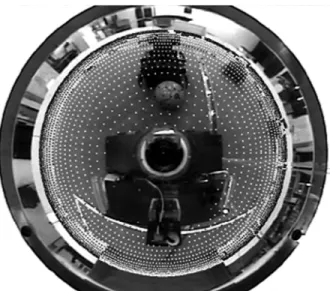
The idea of jump points has been extended to an omnidirectional view as well, where a set of jump points is dened on the image plane, as visualized by white dots in Figure 9. The distribution of these jump points is of high importance. These points are located on the circumference of concentric circles. The center of these circles is the same as the center of the image plane. As one moves toward the center of the image, the number of jump points on each circle reduces and, also, the distance between consecutive circles increases. However, the distance between each two jump points and each two consecutive circles is determined in such a way that at least nine jump points can be located on the smallest object, that is the ball, independent of the distance of the object from the robot.
To determine an object, the color of the image pixels is examined at the jump points. The color detection routine, described in [29], returns a color code for a pixel. This color code stands for one of the standard colors in RoboCup (e.g., red, green, white, black, blue, yellow, light blue and purple). In addition, all other colors are considered as unknown that are represented by only one color code.
Figure9. Jump points shown by white dots are
distributed on circumference of circles.
the ball is detected. If the color at a jump point is red, a search is made in a neighborhood of that jump point to nd the ball. Although there are many algorithms, such as region growing and boundary detection for this purpose [30] and they give a very accurate solution to nding object boundaries in a fast changing environment, like RoboCup, there is a preference for using fast and almost correct algorithms rather than slow and accurate methods. The object detection algorithm works, as follows.
As seen in Figure 10, one starts from a jump point, J, and moves onto two perpendicular lines,L1 and L2, that cross each other at point J. Line L1 passes through points O and J. From jump point
J, one starts moving toward each end of lines L1 and L2, until hitting the border points, A, B and
C, D. A border point is a point on which there is
Figure10. An initial rough estimate to surround the ball
by a sector.
a change of color, from red to a non-red color (ball is red). These four points determine the minimum and maximum angle (1 and 2) and the radius of
sectors intersecting (or in a best case, surrounding) the ball, as shown in Figures 10 and 11. The area inside the sector passing through points A, B, C and
D is taken as an estimate for the ball. However, if K
is the center of this sector, the distance, d (i.e., the distance from jump point J to K), is a measure to check the accuracy of this estimate. Ifdis larger than a certain threshold, the estimate is not a good one. In this case, pointKis taken as a new jump point and the above procedure is repeated, untildbecomes less than the desired threshold. Figure 11 shows an accepted estimate for the ball.
Although this iterative approach seems to be time consuming, it is more accurate compared with methods that can simply estimate the ball position by examining a few adjacent red pixels. The accuracy in determining the correct boundary around the ball (i.e., the most important object of interest during the game) is vital to the correct estimation of the ball distance and angle from the robot.
At this stage, some features of the ball, such as its distance and angle, with respect to the robot, are calculated. As seen in Figure 11,OA and are good estimates for the distance and angle of the ball, with respect to the robot.
LOCALIZATION
Localization is one of the most important and dicult tasks in mobile robots. In RoboCup, where a team of robots should display cooperative behavior to achieve certain goals, the importance of localization is very clear. In short, robots will not be able to perform
Figure11. A nal good estimate to surround the ball by
teamwork in a multi agent system, unless they have relatively accurate information about their own posi-tion, the position of the robots on their team and, also, those of the opposing team on the eld. For self localization in RoboCup environments, methods that use Laser Range Finders and, also, situations in other mobile environments are studied in [31-33].
In [14] the authors have introduced an omnidi-rectional stereo vision system for localization. Basic ideas for robot localization using three xed landmarks (triangulation method), were introduced in [34]. In addition, a localization method, based on landmark detection and a triangulation method, was introduced in [19]. In this method, the authors divided the omni-image into sectors, then, by analyzing the color of the sectors, they determined the sectors containing the blue and red goal and the corner posts. If at least three known landmarks are detected, then, they draw three circles (a circle can be drawn passing through two landmarks and the robot itself). The position and orientation of the robot is estimated to be on the intersection of these three circles. However, during the times when the vision system cannot locate three distinct known landmarks, the proposed localization method cannot locate the robot.
In [16], Lima introduced a self-localization method using omni-vision that performs by nding some known xed reference points in the eld. This method assumes a priori knowledge of the actual distance between 6 horizontal and 5 vertical lines on the soccer eld. A world model is determined, having its center at the eld center. The image processing method determines a set of points on these lines, by detecting their corresponding color transitions. Then, by using the Hough transform [30], the line equations and the intersecting points of these lines are determined. If the system can determine at least three intersecting points, then, these intersecting points are determined as xed known landmarks, or reference points, whose coordinates are known in the world reference frame from the eld model. Then, using the known triangu-lation method, the robot position and orientation are determined.
The main diculty of this approach is that the selected candidate points sent to the Hough transform might not be accurate. In addition, usually, there are many robots on the eld and determining enough correct points on the eld lines is not always possible. So, one may end up in many situations where the Hough transform is not able to nd enough lines thus, not knowing which three reference points should be determined. Therefore, in these cases, the proposed method can not localize the robot.
In [23], the authors presented a localization sys-tem, based on a combination of odometry and vision. For odometry, a dierential method was used that uses
shaft encoders. However, their vision based localization system assumes to have detected the blue and yellow goal upper corners and the robot location is assumed to be on the intersection of two circles passing through the robot center and the goal corners. The authors do not provide detailed vision procedures for this localization. In the following, two localization methods are in-troduced that are based on the omnidirectional viewing system. The rst method, as described in the following section uses the angle of three known xed landmarks, with respect to the robot. These three landmarks are selected from the four intersection points between the eld and the two posts of each goal.
The second method, that is described in the following sections uses the equation of xed known lines. These lines are the border lines between the goals and the eld and the borderlines between the walls and the eld.
Localization Using Angles from Three Fixed
Points
In the following, a localization method is described that uses the angle of three xed landmarks, with respect to the robot coordinate system.
These three landmarks are selected from four intersection points of the posts of goals with the green eld. Let these three land-marks be calledP1,P2, and
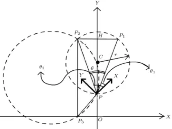
P3. As seen in Figure 12, the locus of points P, that
have a xed angle for P1PP^ 2, is located on a chord
with centerCand radiusr. The center,C, is located on the perpendicular bisector of line segment P1P2, such
that CH= P1P2
2tan andr=
P1P2
2sin, where= 2 1.
Similarly, the locus of pointsP0that have a xed
angle for P2P^ 0P
3 is located on a chord with center
C0 and radius r0. The center, C0, is located on the
perpendicular bisector of line segment P2P3. The
rest of the calculations is as described in the above paragraph for line segment P1P2. For simplicity, in
Figure 12, points P0, C0 and radius r
0, etc. are not
shown, but the corresponding chord is shown with the larger circle.
Now, it is necessary to nd points P1, P2 and
P3 and their angle, with respect to the robot. Using
these angles, one can calculate the above mentioned two chords. These two chords intersect each other at a maximum of 2 points, such that one of these two points is eitherP1, P2 orP3 and the other point isP, which
indicates robot location.
In addition, the orientation of a robot in the eld can be computed using the robot coordinate system and its relative angle to one of landmarksP1, P2 and
P3. However, the fourth landmark is used as a tester
to verify the validity of the result. In the following section, the image processing method is described for nding the landmarks and their angles, with respect to the robot coordinate system.
Finding the Angles of Landmarks with Respect
to Robot Coordinate System
There are two main interesting points that help in nding these angles eciently and reliably in the image plane. The rst point is that the reection of a line (e.g., a vertical column of a goal) that is perpendicular to the eld is a straight line in the image plane that passes through the center of the image plane. So, all points on this straight line have the same angle in the image plane.
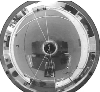
Also, as mentioned before, independent of the robot position in the eld, the upper edges of the wall will always be projected on a circle with a constant radius, such that the center of this circle is located on the image center. In the rest of the paper, this circle is called \surrounding circle". Because the surrounding circle passes through both goals, to nd the angle from four landmarks, there will be a search only on the circumference of this circle. In the following two steps, there is a description of how to nd enough data to determine the angle of the landmarks, with respect to the robot coordinate system. The search algorithm is, as follows:
1. For each point, Pi, on the surrounding circle,
determine if it is located on a blue goal, yellow goal or the wall. To do this, the algorithm checks some points in the neighborhood ofPi, that are located
along a radius of the surrounding circle that passes through Pi. In situations where Pi is located on
a moving object, such as the ball or a robot, the algorithm should determine if this moving object is located near the wall, or it is in a goal area. In such cases, the authors' algorithm checks the pixels on a neighborhood ofPi that is outside the surrounding
circle. Therefore, even in cases when the goal area is blocked by robots, the algorithm will be able to
nd the landmarks correctly. At the end of this step, the points on the surrounding circle can be classied into three categories: Points on the blue goal, points on the yellow goal and points on the wall.
2. In this step, the algorithm nds the goal positions. For example, for the blue goal, it nds the largest consecutive number of points on the surrounding circle that are located on a blue goal.
Figure 13 shows how the angles from the image plane center to the four landmarks are calculated in a case when the goal area is blocked by more than one robot. One can see two small black objects inside each goal. These objects are robots.
Localization Using Fixed Lines
Lines are some of the most convenient landmarks used for localization. Assume one knows the equation of two eld borderlines that are perpendicular to each other (i.e., the borderline between goals and the eld and the one between side walls and the eld). Then, a robot can localize itself by determining its distance from these two lines.
Now, the problem is how to determine the equa-tion of such borderlines accurately. Some of the most common methods of line detection are Robust regression and the Hough transform. Both methods use a set of candidate points that are supposed to be located on the line. The Hough transform is more robust, with respect to noise, and as there is a noisy environment, regarding the accuracy of border point detection, the Hough transform is used to determine the borderline detection.
Figure13. Angles of goal posts, with respect to robot,
The steps needed for line detection are summa-rized, as follows.
1.
Finding Border Points
: To nd border points, the search starts from the points on the circum-ference of the surrounding circle and moves on a radius line toward the center of the circle. A border point is the one detected on its corresponding color transition;2.
Mapping the Points
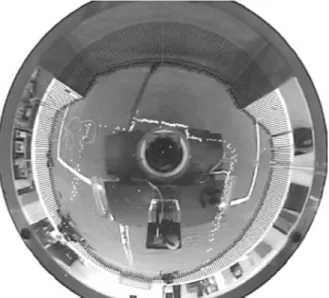
: At this step, the algorithm maps all border points on their corresponding points in the robot coordinate system. But, due to the inaccuracy existing in the mapping of points that are too far from the robot body, such far points are neglected after they are found. In addition, in order to increase the accuracy of the line detection, a few points might be added to the neighborhood of each detected mapped point. This technique is described in the following section.Figure 14, shows a visualization of mapping the eld border points (border of walls and the goals with the eld) on the robot coordinate system. The mapped points are shown as white dots that are scattered along straight lines near the left, right and front side of the robot body;
3.
Using Hough Transform
: Since the accuracy of the slopes of the detected lines are of great importance in the authors' localization algorithm, the idea of adding a number of new border points (i.e., depending on a weight that is dened to be a probability) to the neighborhood of each detected point has been introduced, then, the Hough trans-form has been applied to this new set of points. A more detailed description on this idea is given in [35].Figure14. A visualization of the mapping of eld border
points on the robot coordinate system.
The weight of a point is the probability that a point will be a boundary point, with respect to the noise of the environment. To compute the probability of a cell,C, the number of cells, whose colors are the same as the color ofC in some small neighborhood, are counted and are divided by the total number of cells in that neighborhood. The denition of neighborhood can be any of 8, 15 and 24, depending on the desired accuracy and the speed of calculations.
At this stage, a point C, can be duplicated
K times in the neighborhood of C, where K is proportional to the above-mentioned probability. In other words, more copies of those points are used which have more weight and, thus, such points will have more eect on determining the direction of the estimated line. The reader is referred to [36] for further details on the use of weight.
At this stage, the Hough transform is applied to the new set of border points. The equation of those lines that cross each other at an angle of 90 degrees are determined to be the equation of two borderlines perpendicular to each other.
Now, as described above, the robot can localize itself in the eld by calculating its distance from these two borderlines. In addition, it shall be men-tioned that, by using the color information of border points, one can distinguish the position of the detected lines.
A similar self-localization method, that uses omni-vision and Hough transform, is given in [16]. The advantage of the proposed method is based on introducing new candidate points, depending on the probability of the correctness of the detected border point. This approach increased the accuracy of the detected line equation and, as a result, the accuracy of self-localization as well.
EXPERIMENTAL RESULTS
The omnidirectional viewing algorithms were tested on a processor with an AMD K6, 500MHz processor and 64MB of RAM. The speed of the localization algorithm itself was about 48 frames per second and that of object detection was about 41 frames per second. As a result, the construction of the world model was performed at about 22 frames per second.
During a game, a robot does not always need to localize itself, such times are, when the robot is moving toward the ball, dribbling another robot, kicking the ball, etc. This means that there is no need to have the localization routine run in parallel to other game routines, but it should be called upon request. That is, any time that the robot needs to know its location, the localization program must run.
The proposed vision system was tested at the RoboCup world competition in Seattle in 2001. Error free object detection was obtained whenever the color segmentation was done correctly. In addition, the robot could accurately localize itself in all cases when three xed landmarks or two crossing border lines were correctly detected.
Therefore, the performance of the object de-tection and localization methods depends on the performance of color segmentation and xed land-mark detection. Having accurate color classica-tion and segmentaclassica-tion routines will denitely im-prove the overall performance of the proposed algo-rithms.
CONCLUSION
The experiments in RoboCup have shown that, if one uses only a front view vision system on a robot, there will be several cases when the robots line of sight is blocked by other robots. In such situations, localization methods that are based on only one front view CCD camera will fail, simply because their line of sight is blocked. Moreover, even if a front view CCD camera can see the necessary scene, depending on the position of the robot on the eld and the content of the image acquired by the front view, the robot might fail to nd its location.
In this paper, it has been shown how to use omnidirectional vision for localization, object detection and collision detection. Although it is possible to use infra-red and Laser Range Finders to do some of these jobs, it is believed that it is a good idea to reduce the number of sensors and the hardware complexity of the robot by using only vision sensors. However, one of the problems with vision sensors is that, very fast algorithms must be developed that can be run in real-time speed on the main processor used in the robot. Thinking of the complexity of the real-time environment on a robot soccer eld, the accuracy and real-time speed of a robot vision system remains a challenge.
For self localization, the performance of the pro-posed algorithm, or any other vision based algorithm, highly depends on the accurate detection of predened landmarks, or a set of correct points on the eld border to be used for the Hough transform. In RoboCup, the role of color classication in landmark detection is very important. In this paper, the color classication method, based on the idea of Jump Points, proved to be very fast and reliable in practice, in RoboCup competitions.
However, more work needs to be done in this eld when environment light change occurs during the game. This is a new challenge for researchers working in this eld.
ACKNOWLEDGMENT
The authors would like to especially thank all Sharif CE team members from previous years, specially A. Fourghnasiraie, R. Ghorbani, M. Kazemi, B. Sad-jad, H. Chitsaz, F. Mobbaser and M.T. Hajiaghayi who made many contributions to the development of the team. The authors also would like to express their sincere gratitude to all high-ranking managers of Sharif University of Technology, especially Professor S. Sohrabpoor, the chancellor, for several years of support in developing this research. In addition, the nancial sponsors are gratefully acknowledged for their valuable contributions.
REFERENCES
1. Lima, P., Balch, T. and Fujita, M. et al. \RoboCup 2001, a report on research issues that surfaced during the competitions and conference",IEEE Robotics and Automation Magazine, pp 20-30 (June 2002).
2. www.robocup.org.
3. Svoboda, T. \Central panoramic cameras design, ge-ometry, Ego-motion", Ph.D Thesis, Center for Ma-chine Perception, Department of Cybernetics, Faculty of Electrical Engineering, Czech Technical University, Czech Republic (Sept. 1999)
4. Nayar, S. \Omnidirectional video camera", In Pro-ceedings of the 1997 DARPA Image Understanding Workshop, pp 1431-1437, New Orleans, Louisiana (1997).
5. Baker, S. and Nayar, S.K. \A theory of single-viewpoint cataleptic image formation", International Journal of Computer Vision,35(2), pp 175-196 (1999).
6. Ollis, M., Herman, H. and Singh, S. \Analysis and design of panoramic stereo vision using equi-angular pixel cameras", Technical Report CMU-RI-TR-99-04, Carnegie Mellon University, Pittsburgh Pennsylvania (1999).
7. Bogner, S., Hanna, D. and Brosinsky, C. \Application of panoramic viewing systems to unmanned vehicles", InProceedings of the 1996 Conference of the Interna-tional Association of Unmanned Vehicle Systems, pp 853-862 (1996).
8. Yagi, Y., Kawato, S. and Tsuji, S. \Real-time omni-directional image sensor for vision-guided navigation",
IEEE Transactions on Robotics and Automation, 10,
pp 11-22 (1994).
9. Paletta, L., Frintrop, S. and Hertzberg, J. \Robust localization using context in omnidirectional imaging", In2001 IEEE Intl. Conf. on Robotics and Automation (ICRA 2001), pp 2072-2077, Seoul, Korea, May 21-26 (2001).
10. Thorpe, C. et al. \Vision and navigation for the Carnegie-Mellon Navilab",IEEE Trans. Pattern Anal. Mach. Intell.,PAMI-10(3), pp 362-373 (1998).
11. Yamazawa, K., Yagi, Y. and Yachida, M. \Obstacle detection with omnidirectional image sensor hyper-omni vision", IEEE International Conf. on Robotics and Automation, pp 1062-1067 (May 1995).
12. Gonzalez, J.J., Lacroix, B. and Lacroix, S. \Rover localization in natural environments by indexing panoramic images", Proceedings of the 2002 IEEE International Conference on Robotic Proceedings Robotics and Automation(2002).
13. Stratmann, I. \Omnidirectional imaging and optical ow",Proceedings of the IEEE Workshop on Omnidi-rectional Vision (OMNIVIS 2002), held in conjunction with ECCV '02 (June 2, 2002, Copenhagen, Denmark), IEEE Computer Society, pp 104-114, Los Alamitos, CA, USA (2002).
14. Matsuoka, T., Araoka, M. and Hasegawa, T. et al. \Lo-calization and obstacle detection using omnidirectional vertical stereo vision", RoboCup-2001: Robot Soccer World Cup V, pp 428-434, LNCS, Springer (2001) 15. Suzuki, S. and Asada, M. \An application of
vision-based learning in RoboCup for a real robot with omnidirectional vision system and the team description of Osaka University \trackies"", In M. Asada and H. Kitano, Eds., RoboCup 98: Robot Soccer World Cup II,1604, pp 316-325, LNCS Springer (1999).
16. Marques, C.F. and Lima, P.U. \Vision based self-localization for soccer robots",Processing of the 2000 IEEE/RSJ International Conference on Intelligent Robots and Systems, Takamatsu, Japan (2000). 17. Menegatti, E. and Pagello, E. et al. \Designing an
omnidirectional vision system for a goal keeper robot",
RoboCup-2001, Robot Soccer World Cup V, pp 81-91, LNCS, Springer (2001).
18. Birk, A., Coradeschi, S. and Tadojoro, S., Eds.
RoboCup 2001: Robot Soccer World Cup V, LNCS, Springer (2002).
19. Samani, A.H., Abdollahi, A., Ostadi, H. and Rad, S.Z. \Design and development of a comprehensive omnidirectional soccer player robot", International Journal of Advanced Robotic Systems, 1(3), pp
191-200 (191-2004).
20. Junhong, J.I., Ploeger, G. and Bredenfeld, P. \An omni-vision based self-localization method for soccer robot",Proceedings of Intelligent Vehicles Symposium, pp 276-281, IEEE 9-11 (June 2003).
21. The RoboCup Federation, RoboCup-99 Stockholm, Award Winners, http://www.robocup.org/ games/99stockholm/3132. html.
22. The RoboCup Federation, RoboCup-2000, Melbourne, Award Winners, http://www.robocup.org/ games/ 2000Melbourne/3144. html.
23. Ishiguro, H., Compact Omnidirectional Sensors and Their Applications, M & E, Kougyou-Chosakai, March 1998 (In Japanese), available at: http://www.accowle.com/english/spec.html.
24. Bonarini, A. et al. \An omnidirectional vision sensor for fast tracking for mobile robots", InIEEE Trans. on Instrumentation and Measurement,49(3), pp 509-512
(June 2002).
25. Suzuki, S., Asada, M. et al. \Behavior learning for a mobile robot with omnidirectional vision enhanced by an active zoom mechanism", InProc. of Intelligent Autonomous System5 (IAS-5), pp 242-249 (1998). 26. Hundelshausen, F.V. \An omnidirectional vision
sys-tem for soccer robots", Master Thesis, Institut for In-formatik, Freie University Berlin, Berlin (April 2001). 27. Hundelshausen, F.V., Behnke, S. and Rojas, R. \An omnidirectional vision system that nds and tracks color edges and blobs", RoboCup 2001: Robot Soccer World Cup V, pp 374-379, LNCS, Springer (2002) 28. Jamzad, M., Chiniforushan, E. and Sadjad, S.B.
\Ob-ject detection in changing environment of middle size RoboCup and some applications",IEEE Int. Symp. on Intelligent Control, Vancouver, Canada, pp 807-810, October 27-30 (2002).
29. Jamzad, M. et al. \A fast vision system for middle size robots in RoboCup", InRoboCup-2001: Robot Soccer World Cup V, Birk, A. et al., Eds., pp 71-80, LNCS, Springer (2002).
30. Gonzalez, R.C. and Woods, R.E., Digital Image Pro-cessing, 2nd Ed., Prentice-Hall (2002)
31. Gotmann, J.S., Weigel, T. and Nebel, B. \Fast, accurate, and robust self-localization in the RoboCup environment",RoboCup 99: Robot Soccer World Cup III,1856, pp 304-317, LNCS, Springer (2000).
32. Iocchi, L. and Nardi, D. \Self-localization in the RoboCup environment", InRoboCup 99: Robot Soccer World Cup III, 1856, pp 318-330, LNCS, Springer
(2000).
33. Olson, C.F. \Probabilistic self-localization for mobile robots", In IEEE Transactions on Robotics and Au-tomation,16(1), pp 55-66 (February 2000).
34. Krotkov, E. \Mobile robot localization using a single image",Proc. IEEE lnt. Con. J. Robotics and Automa-tion, pp 978-983 (1989).
35. Hajiaghayi, M.T. and Jamzad, M. \Simple, fast and robust self-localization in environments similar to the RoboCup environment", InCARs and FOF'2002, 17th International Conference of CAD/CAM, Robotics and Factories, Porto, Portugal (July 2002).
36. Parhami, B. \Voting algorithms",IEEE Transactions on Reliability,43(3), pp 617-629 (1994).