Proceedings of the
Third International Workshop on Graph Based Tools
(GraBaTs 2006)
Object Oriented and Rule-based Design of Visual Languages
using Tiger
Claudia Ermel, Karsten Ehrig, Gabriele Taentzer, and Eduard Weiss
12 pages
Guest Editors: Albert Z ¨undorf, Daniel Varr ´o
Managing Editors: Tiziana Margaria, Julia Padberg, Gabriele Taentzer
Object Oriented and Rule-based Design of Visual Languages
using Tiger
Claudia Ermel1, Karsten Ehrig2, Gabriele Taentzer3, and Eduard Weiss1
1Institut f¨ur Softwaretechnik und Theoretische Informatik,
Technische Universit¨at Berlin, Germany [email protected],[email protected]
2Department of Computer Science,
University of Leicester, United Kingdom [email protected]
3Fachbereich Mathematik und Informatik,
Universit¨at Marburg, Germany [email protected]
Abstract: In this paper we present the state-of-the-art of the TIGER environment for the generation of visual editor plug-ins in Eclipse, with the focus on itsDesigner component, a visual environment for object oriented and rule-based design of vi-sual languages. Based on an alphabet for finite automata we show how a vivi-sual language can be designed by defining the abstract and concrete syntax of the visual language and syntax directed editing operations in the generated editor plug-in. For the graphical layout we use the Graphical Editing Framework (GEF) of ECLIPSE which offers an efficient and standardized way for graphical layouting.
Keywords:visual languages, editor generation, visual editor, graph transformation, Eclipse
1
Introduction
Domain specific modeling languages are of growing importance for software and system de-velopment. Meta tools are needed to support the rapid development of domain-specific tool environments. The basic component of such environments is a domain-specific visual editor. A visual language (VL) definition based on a meta model in combination with syntax rules defin-ing syntax-directed editor commands is used in TIGER (Transformation-based Generation of Environments) to generate a corresponding visual editor. On the one hand, a visual language definition captures the visual symbols, links and relations of the domain specific modeling lan-guage (the alphabet); on the other hand, a syntax graph grammar defines precisely which editor operations are allowed and restrict the visual sentences of the VL to correct diagrams.
post-conditions of each command. The application of such syntax rules to the underlying syn-tax graph of a diagram is performed by the graph transformation engine AGG [Tae04]. TIGER extends AGG by a concrete visual syntax definition for flexible means for visual model repre-sentation. From the definition of the VL, the TIGERGeneratorgenerates Java source code. The generated Java code implements an ECLIPSEvisual editor plug-in based on GEF which makes use of a variety of GEF’s predefined editor functionalities. Thus, graphical layout constraints are defined and solved with efficient Java methods without using complex constraint solving algo-rithms like in GENGED [BEW03] or DIAGEN[Min02], and the generated editors appear in a timely fashion, conforming to the ECLIPSEstandard for graphical tool environments.
Note that graph transformation-based editors, in contrast to related meta-model-based editors like GMF [GMF05], AToM3 [dLVA04] or Pounamou [NLG05], do not only offer basic editor commands, the so-calledCRUD operations (Create, Read, Update, Delete), but they can also offer complex editing commands which insert or manipulate larger model parts consisting of a number of elements. With complex editing commands, model optimizations, such as model refactoring, as well as model simulation can be performed.
TIGER [EEHT05, Tig05] is the successor project of GENGED [BEW03, Bar02], with the objective to make extensive use of today’s modern functionalities for visual model-driven devel-opment and integration offered by the Eclipse platform and its plug-in mechanism. Hence, both the TIGERDesigner component for visual VL definition and the TIGER-generated visual edi-tors are ECLIPSEplug-ins, based on the common paradigm for visual creation, management and navigation of resources. The features of domain-specific editors generated by GENGED, DIA-GENand ATOM3(e.g. for layouting diagrams, undo/redo, zooming, etc.) partly differ heavily from modern standards. Moreover, the generated environments are not meant to be integrated into other existing tool environments. As stand-alone applications they do not always offer the standard look-and-feel of common editor features.
In this paper we focus on the TIGERDesigner for visual editing of visual language specifi-cations as part of the TIGER environment [Tig05]. The second main component of TIGER is the TIGERGenerator for generating rule-based editor plug-ins in ECLIPSE. The generator has already been presented in [EEHT05].
The paper is organized as follows: Section 2 reviews the basic concepts for visual language specification based on graph transformation, and introduces the TIGERperspective for VL design in ECLIPSE. Section 3 goes into the details and describes how a VL is specified using the TIGER Designer, by defining on the one hand the abstract and concrete syntax of the VL alphabet, using the visual abstract syntax editor and layout view, and on the other hand, by defining the editing operations using the visual rule editor. Section 4 shows how a visual editor is generated as ECLIPSEplug-in from the VL specification. In Section 5, we discuss ongoing and future work concerning the TIGERenvironment.
2
Visual Language Design based on Graph Transformation
visual-ization of the abstract syntax. While the concrete syntax contains the concrete layout of a visual notation, the abstract syntax shows the underlying structure, i.e. it provides a condense repre-sentation to be used for further processing. Similarly to textual language definition, grammar rules define the language, but for visual languages, graph rules are used to manipulate the graph representation of a language element.
2.1 VL Design Concepts based on Graph Transformation
For the application of graph transformation techniques to VL design, typed attributed graph transformation systems [EEPT06] have proven to be an adequate formalism. Roughly spoken a typed attributed graph transformation rule p= (L→R)consists of a pair of typed attributed graphsLandR (its left-hand and right-hand sides) and a mapping fromLtoR. Symbols and links appearing inLare matched with the elements of the current editor diagram and deleted or preserved according to their mapping toR. New symbols and links are created if they appear in Ronly. Adirect graph transformationwrittenG=p⇒,o H, means that diagramGis transformed into diagramHby applying rule pat the occurrenceoofLinG.
A VL is modeled basically by analphabet, an attributed type graph which captures the defini-tion of the underlying symbols and reladefini-tions which are available. Sentences or diagrams of the VL are given by attributed graphs typed over the type graph. The abstract alphabet is extended by defining the concrete layout of diagrams. At the concrete syntax level, the VL alphabet defines the figures and their properties which are used to visualize the underlying abstract symbols.
Usually, the set of visual diagrams (sentences) over an alphabet should be further restricted to the meaningful ones. By defining this restriction via graph rules, the constructive way is followed (as opposed to the declarative MOF approach [MOF05], where OCL constraints are used). The application of abstract syntax graph rules builds up abstract syntax graphs of valid diagrams. Together with a suitable start graph, the set of syntax rules forms the syntax graph grammar which defines the models belonging to a VL in a well-defined and constructive way.
2.2 The TIGERPerspective for VL Design in ECLIPSE
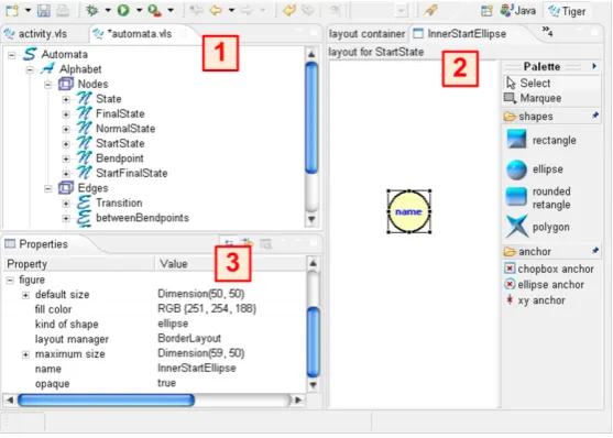
The main difference between the TIGER Designer and related stand-alone environments for graph transformation-based VL design such as GENGED, DIAGEN and ATOM3, is the use
properties view ( 3 in Figure1) allows to change values for graphical layout properties of the ellipse figure selected in the visual editor.
Figure 1: The TIGERPerspective in ECLIPSE
In the following, we describe how the diverse views and editors of the TIGERDesigner are used to define a VL specification consisting of a VL alphabet and a VL syntax grammar.
3
Designing Visual Languages using Tiger
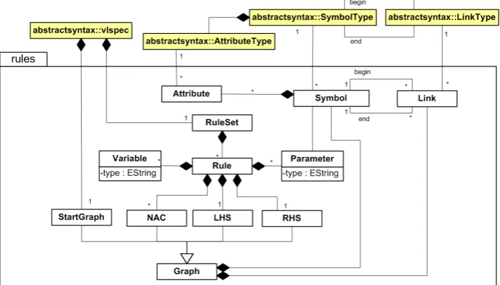
As discussed in the previous section, a VL specification (VLSpec) consists of anAlphabet con-taining the available symbols and links of the VL and their layout, aRuleSetcontaining syntax rules which define possible editing operations to construct diagrams, and aStartGraph, defining the initial diagram the syntax rules are applied to. In alphabets, rules and diagrams we distinguish the abstract syntax (the internal representation of diagrams as graphs without layout information) from the concrete syntax (describing additionally the layout properties and constraints).
3.1 The VL Alphabet
Figure 2: VL Specification: Abstract Syntax of an Alphabet
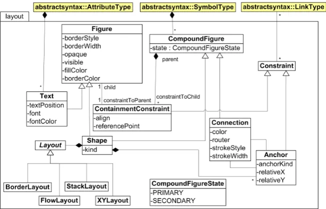
The graphical layout (the concrete syntax) is given by additional classes extending the class diagram shown in Figure 2. The TIGER Designer stores the concrete layout information for symbols and links in the designer model based on the meta model shown in Figure3 which is closely connected to the layout relations of Eclipse GEF [GEF06].
Figure 3: VL Specification: Concrete Syntax
standard layout styles such asStackLayout,BorderLayout,XYLayout, andFlowLayout. Connec-tion Anchorsdescribe the relation betweenShapesandConnections. GEF layoutConstraintsare handling the layout positions inside ofFiguresviaContainmentConstraints, for example aText Figure is located inside anEllipsefigure.
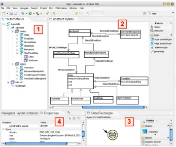
Figure4shows the TIGERPerspective for designing a visual language for finite automata.
Figure 4: VL Design of the Automata VL with the TIGERDesigner
While the tree view on the left-hand side ( 1 in Figure 4) shows the symbol types of the automata alphabet, the syntax rules and the start graph of the automata syntax grammar, the abstract syntax can be defined in the abstract syntax panel to the right ( 2 in Figure4), where the abstract syntax of the automata alphabet is shown. The concrete layout of a symbol type is defined via a graphical editor shown at the bottom of the right-hand side ( 3 in Figure 4). The layout for theStartFinalState symbol (a start state which is a final state as well) is given by an invisible rectangle, containing the start marker (a polygon), and an outer and inner ellipse selected from theshapesmenu of the editorPalette. Moreover, an attributenameis represented by a text figure, connected via ananchorto the inner ellipse figure. TheProperties Viewon the left side of the bottom ( 4 in Figure4) shows the layout properties like text width and style of the figure selected in the editor, here the text figure of theStartFinalStatesymbol. In the same wayNormalState,StartState,FinalStateandStateare defined where the last one represents the other states via an inheritance relation defined in the abstract syntax.
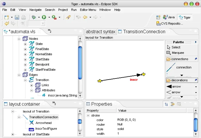
view for connecting the Transition with a State. The concrete layout is given by Transition Connection defining a lineconnectionwith a closed arrowdecorationfrom the editorPalette. For better orientation, the begin and end points of a connection are visualized by small block arrows (see Figure 5). An inscription attribute inscr is located close to the end point of the transition line via a layout constraint. The Properties Viewshows the layout properties of the TransitionConnectionwith black color, solid line style, and normal width.
Figure 5: Creating aTransitionconnection in the TIGERDesigner
3.2 The VL Syntax Grammar
Language constraints restricting the set of valid diagrams over an alphabet are modeled by re-stricting the set of editing commands, i.e. graph transformation-based editors are usually syntax-directed. An editor command is modeled as a graph rule (typed over the language’s alphabet) being applied to the abstract syntax graph of the current diagram. The graph transformation ap-proach to language definition is a constructive one, since syntax rules are used to build up all language instances from an initial state (the start graph). The start graph together with the set of syntax rules and the underlying VL alphabet, are calledVL syntax grammarbecause it defines the complete syntax of the visual language.
left-hand sideLto the right-hand sideRand fromLto the NACs are given by sets of mappings for symbols and links.
Figure 6: VL Specification: Syntax Grammar
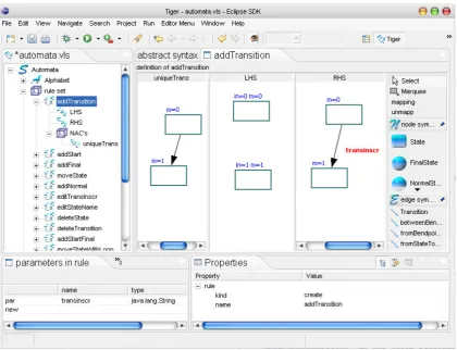
In the TIGER rule editor in Figure7, the editor operations for syntax directed editing of au-tomata are defined. The ruleaddTransition inserts a Transition between two arbitrary States represented by solid rectangles. In fact, the abstract nodeStatepreserves the user from defining different rules for each possible pair of concrete state figures, for example to connect a Start-Statewith aNormalState. The left-hand side of the rule defines theStatesto be selected by the user as input parametersin=0andin=1of the rule. After rule application, aTransitionwith the inscriptiontransinscr is inserted between the previousStates, where the mapping between the left- and right-hand side is indicated withm=0andm=1. The NACuniqueTransensures that no Transitionin the same direction exists before the rule application. Instead, we allow inscriptions consisting of more than one character for one transition. The transition nametransinscris listed as input parameter in the viewparameters in rule of type java.lang.String. For such attribute parameters, a dialog window pops up when performing the corresponding editor operation in the generated environment, asking the user to specify the transition inscription.
In theProperties Viewthekindattribute specifies the rule behavior:
• The name of acreateoperation will appear as entry in the editor palette of the generated editor for inserting a new symbol or a larger structure consisting of several symbols (a sub-diagram) in the editor panel.
• Adeleteoperation appears as an entry in the context menu of a symbol for deletion of the symbol or an associated sub-diagram.
Figure 7: Editing of the syntax ruleaddTransitionin the Tiger Designer
• Aneditoperation appears as another context menu entry which allows to change the prop-erties of the associated symbol.
4
Generation of Eclipse Editor Plug-ins
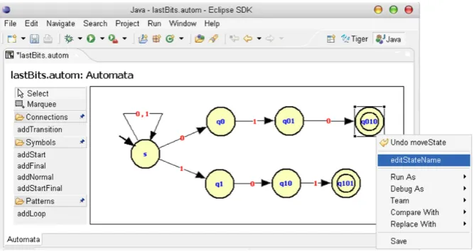
After the specification of a visual language has been completed, the TIGERGenerator can be invoked for generating the Java code of the envisaged editor plug-in. TheTiger Generatoruses Java Emitter Templates (JET) as part of the Eclipse Modeling Framework (EMF) [EMF06] for code generation. In code templates, place holders are filled with values given from the vi-sual language specification. The generated Java code may be executed directly in the Eclipse Runtime-Workbench. Figure8shows the generated editor plug-in for automata. In this editor, an automaton is shown generating the languageL={w∈ {0,1}∗|wis ending with 010 or 101}.
oper-Figure 8: Generated Automata Editor Plug-in in ECLIPSE
ation (e.g. addTransition) has been selected in the palette, the required match symbols must be selected in the editor panel (the source and target state for the transition have to be clicked on). If an input parameter is defined for the syntax rule, a dialog pops up and asks for an attribute value (e.g. the transition inscription has to be given). Now, the underlying creation rule is applied, i.e. the transition is inserted between the two states. Note thataddLoopis a creation pattern, because internally, a loop consists of three connections and two bendpoints (see the loop at the start state in Figure8). Thus, the bendpoints can be moved by the user to readjust the loop. Move rules are applied simply when a symbol (or a set of symbols marked by Marquee) is dragged by the mouse. A move rule may also be defined for a symbol pattern. For example, in the automata VL, we defined a move rule moving a state node together with a loop. Deletion rules and editing rules appear in the context menu which is evoked by the right mouse button after a symbol has been selected. Figure8shows the context menu for final stateq010, where it is possible to evoke the operationeditStateName.
5
Conclusion
In this paper we have described the state-of-the-art of the TIGERenvironment (http://tfs.cs.tu-berlin. de/tigerprj) with focus on theDesignerfor specifying visual languages in ECLIPSE.
the result would still be a syntax-directed editor. Since both the meta-model-based approach (generating visual free-hand editors) and the graph-transformation-based approach (generating syntax-directed editors), have their advantages and disadvantages (see [Tae06]), we propose as future work to combine both approaches. This means that starting with a meta model only, a simple editor would be generated offering the basic editor operations for each symbol. A syntax check can be added by defining well-formed-ness rules or graph constraints (comparable to an OCL checker in addition to a meta model). For the generation of complex editor commands, an additional specification is needed using syntax rules.
In order to further customize the generated editors, work is in progress to replace the under-lying AGG graph transformation engine by a transformation engine based on Eclipse EMF. In this way, genereated editors can be based on already existing domain models. Currently, if the generated editors have to be further adapted to specific needs, the Java code may be extended by hand. So far, changing the generated code is not specifically supported by TIGER, so the user must take into account that a regeneration by TIGERmight overwrite hand-written code changes. As a further improvement at the concrete syntax level we plan to extend TIGERto allow the nesting of figures belonging to different symbol types. With this extension, a TIGERuser would be able to specify not only graph-like visual languages, but also more complex ones, like e.g. hierarchical Statecharts.
Furthermore, the TIGERenvironment has recently been extended by amodel transformation graph grammar which defines the model transformation between models of either two differ-ent VL specifications (exogenous), or between models belonging to the same VL specification (endogenous). An exogenous model transformation between two generated editor plug-ins in TIGERis described in [EEEP06], where activity diagrams are transformed into Petri nets. Con-sidering our automata example, we might define an endogenous model transformation based on the automata VL specification to transform non-deterministic automata into deterministic ones in our generated automata editor plug-in. An example for a related model transformation envi-ronment in ECLIPSEbased on graph transformations is VIATRA2,which is part of the ECLIPSE Generative Modeling Tools [GMT06]. Work is in progress to support the definition of model transformations directly in the TIGERDesigner, using the concrete layout of the visual modeling languages.
These extensions can be considered as a starting point for the generation of comprehensive domain-specific visual modeling environments.
Bibliography
[Bar02] R. Bardohl. A Visual Environment for Visual Languages. Science of Computer Programming (SCP), 44(2):181–203, 2002.
[BEW03] R. Bardohl, C. Ermel, and I. Weinhold. GenGED - A Visual Definition Tool for Visual Modeling Environments. In J. Pfaltz and M. Nagl, editors,Proc. Application of Graph Transformations with Industrial Relevance (AGTIVE’03), 2003.
Section on Graph Transformations and Visual Modeling Techniques, 3(3):194–209, 2004.
[EEEP06] H. Ehrig, K. Ehrig, C. Ermel, and J. Padberg. Construction and Correctness Anal-ysis of a Model Transformation from Activity Diagrams to Petri Nets. In I. Troch and F. Breitenecker, editors,Proc. Intern. IMCAS Symposium on Mathematical Mod-elling (MathMod). ARGESIM-Reports, 2006.
[EEHT05] K. Ehrig, C. Ermel, S. H¨ansgen, and G. Taentzer. Generation of Visual Editors as Eclipse Plug-ins. InProc. 20th IEEE/ACM International Conference on Automated Software Engineering, IEEE Computer Society, Long Beach, California, USA, 2005.
[EEPT06] H. Ehrig, K. Ehrig, U. Prange, and G. Taentzer. Fundamentals of Algebraic Graph Transformation. EATCS Monographs in Theor. Comp. Science. Springer, 2006.
[EMF06] Eclipse Consortium. Eclipse Modeling Framework (EMF) – Version 2.2.0, 2006. http://www.eclipse.org/emf.
[GEF06] Eclipse Consortium. Eclipse Graphical Editing Framework (GEF) – Version 3.2, 2006. http://www.eclipse.org/gef.
[GMF05] Eclipse Consortium. Eclipse Graphical Modeling Framework (GMF) – Version 2.0, 2005. http://www.eclipse.org/gmf.
[GMT06] Eclipse Generative Modeling Tools (GMT)http:// www.eclipse.org/ gmt, 2006.
[Min02] M. Minas. Specifying Graph-like Diagrams with Diagen. Electronic Notes in Theo-retical Computer Science, 72(2), 2002.
[MOF05] Object Management Group. Meta-Object Facility (MOF), Version 1.4, 2005. http: //www.omg.org/technology/documents/formal/mof.htm.
[NLG05] J. Hosking N. Liu and J. Grundy. A Visual Language and Environment for Specifying Design Tool Event Handling. In M. Erwig and A. Sch¨urr, editors,Proc. IEEE Sym-posium on Visual Languages and Human-Centric Computing (VL/HCC’05), IEEE Computer Society, 2005.
[Tae04] G. Taentzer. AGG: A Graph Transformation Environment for Modeling and Val-idation of Software. In J. Pfaltz, M. Nagl, and B. Boehlen, editors, Application of Graph Transformations with Industrial Relevance (AGTIVE’03), volume 3062 of LNCS, pages 446 – 456. Springer, 2004.
[Tae06] G. Taentzer. Towards Generating Domain-Specific Model Editors with Complex Editing Commands. InProc. Workshop Eclipse Technology eXchange(eTX), 2006.